PROGRAMMING AND CUSTOMIZING THE PIC MICROCONTROLLER 3rd phần 4 docx
Bạn đang xem bản rút gọn của tài liệu. Xem và tải ngay bản đầy đủ của tài liệu tại đây (1.14 MB, 130 trang )
PIC18 INSTRUCTION SET 363
; i = ArrayVar(3) // Simulate an array read
movlw 2 ; Calculate Offset to 3rd Element
addwf FSR, f
movf INDF, w ; Get the 3rd Element
movwf i ; and store it
movlw -2 ; Restore FSR to point to first element
addwf FSR, f
This code has to first add 2 to the current address in the FSR, followed by loading
and storing the third element and then returning the index pointer to the first element
in the array. Now, compare this to the same code for the PIC18 in which FSR0 (which
means that the PLUSW0 register will be used to access the data) points to the start of
ArrayVar.
; i = ArrayVar(3) // Simulate an array read
movlw 2 ; Want Offset to the 3rd Element
movff PLUSW0, i ; Move Contents of ArrayVar(3) into i
The PREINC and POSTDEC INDF registers can be used for popping and pushing,
respectively, data onto a stack pointed to by an FSR register. The POSTDEC INDF reg-
ister is used for the push operation because it will allow the access of pushed data using
the PLUSW INDF register as shown in the previous example.
Using FSR0 for the stack, the byte push function could be as simple as:
BytePush: ; Push the contents of “i” onto the stack
movff i, POSTDEC0
return
and the byte pop could be:
BytePop: ; Pop the top of the stack
movff PREINC0, i
return
The PLUSW INDF register comes in useful for high level functions in which data
has been pushed onto the stack to implement temporary variables. In the example below,
I have specified a function that uses a data stack and with the parameters and local vari-
ables (the same thing) being pushed onto a stack implemented with FSR0:
; int StackDemo(char i, char j) // “i” is stack top, “j” is one less
; {
; char k = 0; //
“k” is at two less than stack top
movlw 0 ; Initialize “k” to zero
movwf POSTDEC, 0
;
; i = j + k; // Perform a basic calculation
movlw 2 ; Get offset to “j”
Simpo PDF Merge and Split Unregistered Version -
364 USING THE PIC MCU INSTRUCTION SET
movff Temp, PLUSW0 ; Store value in “Temp”
movlw 1 ; Get offset to “k”
movf PLUSW0
addwf Temp, f, 0 ; Add “k” to “j” in “Temp”
movlw 3 ; Get offset to “i”
movff PLUSW0, Temp ; Store result
While this code may look very complex, it is actually simple and, once you are com-
fortable with it, very easy to implement. This capability is also critical for efficient
implementation of compilers that implement local variables as shown here.
DATA PROCESSING INSTRUCTIONS
The PIC18 has some added flexibility and conventional capabilities compared to the other
PIC microcontroller processors. As you look through the PIC18 instruction set, you will
see that the additions and modifications to its instruction set make it more similar to that
of other processors while retaining the PIC18’s ability to create very efficient code.
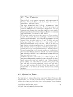
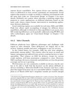
The most significant addition to the PIC18’s data processing instructions is the
subfwb (Fig. 7.49) instruction. This instruction carries out a subtract operation with
borrow in the order most people are familiar with if they have worked with other proces-
sors. Instead of the typical PIC microcontroller subtraction instruction:
Result = (Source Value) – WREG [- !C]
the subfwb instruction executes as:
Result = WREG – (Source Value) - !C
Program Memory
Register Space
Register Address Bus
PC
Program
Counter
Stack
ALU
Fast Stack
InstructionRegister/
Decode
Second Instruction
Register
STATUS
WREG
BSR
FSR
File
Registers
Instruction Bit Pattern:
12345678 12345678
Instruction Operation:
Destination =
WREG - Reg - !C
Flags Affected:
N, OV, C, DC, Z
Instruction Cycles:
1
Notes: This instructionbehaves like a “Traditional” Subtract
and is different from the “Standard” subtraction Instructio
ns
Available in the other PICmi
cro architectures
010101da ffffffff
Figure 7.49 The
subfwb
instruction provides the expected subtract operation
instead of the addition of the negated value of WREG used by the other subtract
instructions.
Simpo PDF Merge and Split Unregistered Version -
PIC18 INSTRUCTION SET 365
This instruction frees you from the need of thinking backwards when subtraction
instructions are used in an application. To use the subfwb instruction, WREG is loaded
with the value to be subtracted from (the subtend) and the value to take away (the sub-
tractor) is specified in the instruction. This means that if you have the statement:
A = B – C
the values of the expression can be loaded in the same left to right order as the PIC micro-
controller instructions and use the sequence:
bcf STATUS, C, 0
movf B, w, 0
subfwb C, w, 0
movwf A, 0
This is the same order as would be used in most other processors. Note that I reset
the carry flag before the instruction sequence to avoid any possibilities of the carry being
reset unexpectedly and taking away an extra 1, which will be very hard to find in
application code.
A PIC18 16-bit subtraction operation could be:
bcf STATUS, C
movf B, w, 0
subfwb C, w, 0
movwf A, 0
movf B + 1, w, 0
subfwb C + 1, w, 0
movwf A + 1, 0
Or if you want to save on the instruction used to clear the carry flag at the start of the
sequence:
movf C, w, 0
subwf B, w, 0
movwf A, 0
movf B + 1, w, 0
subfwb C + 1, w, 0
movwf A + 1, 0
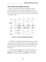
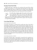
Another difference between the PIC18 and the other PIC microcontroller processors
is the inclusion of the negf (Fig. 7.50) instruction, which can negate any register in
the PIC18’s register space.
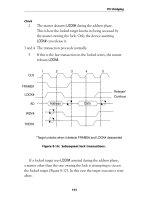
The single instruction cycle multiply instructions multiply the contents of WREG
against the contents of another register (mulfw) or a constant (mullw) and store the
16-bit product in the PRODH:PRODL register combination (Fig. 7.51). These instruc-
tions are very well behaved and will work for 2’s complement numbers and can pro-
vide you with some basic digital signal processing (DSP) capabilities in the PIC18.
Simpo PDF Merge and Split Unregistered Version -
366 USING THE PIC MCU INSTRUCTION SET
EXECUTION CHANGE INSTRUCTIONS
The PIC18’s execution change instructions, upon first glance, should be very familiar to
you if you are familiar with the other PIC microcontroller families. The PIC18 has the
btfsc, btfss, goto, and call of the low-end and mid-range PIC microcontrollers
along with the compare and skip on equals (cpfseq), greater than (cpfsgt), and less
than (cpfslt). The PIC18 also has the enhanced increment and skip on result not equal
to zero (infsnz and dcfsnz). Along with these similarities, the PIC18 has four new
features that you should be aware of (and remember their availability) when you are devel-
oping applications for it.
The first feature that you should be aware of is the goto and call instructions, which
can directly any address in the program memory space. As shown in Fig. 7.52, these
instructions are built from two 16-bit words and contain the entire 20 word address bits
to allow you to jump anywhere in program memory.
Program Memory
Register Space
Register Address Bus
PC
Program
Counter
Stack
ALU
Fast Stack
Instruction Register/
Decode
Second Instruction
Register
STATUS
WREG
BSR
FSR
File
Registers
Instruction Bit Pattern:
12345678 12345678
Instruction Operation:
Reg = (Reg ^ 0x0FF) + 1;
Flags Affected:
C, DC, N, OV, Z
Instruction Cycles:
1
Notes: All Flags are Affected by this Instruction
0110110a ffffffff
Figure 7.50 The
negf
instruction will two’s complement ny register in the
PIC18 register space.
PRODH:PRODL
8x8 Multiplier
WREG
Parm (Register for mulwf
Constant for mullw)
Figure 7.51 The two single instruction
cycle 8 by 8 multiplication instructions store
their result in PRODH:PRODL.
Simpo PDF Merge and Split Unregistered Version -
PIC18 INSTRUCTION SET 367
The call instruction (as well as the corresponding return) instruction has the capa-
bility, when a 1 is specified as the s bit at the end of the instruction, of saving the con-
text registers WREG, BRS, and STATUS in shadow registers of the fast stack, which
are retrieved by the return instruction by specifying a 1 as well. The issue that you
should be aware of for the context save is that you can only save one set of values on
the fast stack and the context values of the mainline are always saved when an interrupt
is acknowledged. This limits the usability of the context register save to applications
that only have a single deep call and no interrupts.
For your first PIC18 applications, I would recommend that you use the instruction
set’s single word instructions only. The only time you should be using the goto or call
instructions is if you have to access a memory location outside the range of the relative
branches. This range is –512 to +511 instruction addresses for the bra (branch always)
and rcall (relative call) instructions and –64 to +63 instruction addresses for the con-
ditional branch instructions that I will discuss below. The rcall instruction informa-
tion is shown in Fig. 7.53.
Along with using the single word execution change instructions, I also recommend
that you be careful when using the $ directive and branching relative to it. When the
assembler is calculating addresses, it works on a byte basis, not a word basis as it does
for other PIC microcontrollers. This means that you must multiply the number of instruc-
tions by 2 to get the correct address. Consider the simple delay loop:
movlw 47 ; Loop 47x3 instruction cycles
decfsz WREG, f, 0
bra $ - 1
Program Memory
Register Space
Register Address Bus
PC
Program
Counter
Stack
ALU
Fast Stack
InstructionRegister/
Decode
Second Instruction
Register
STATUS
WREG
BSR
FSR
Instruction Bit Pattern:
12345678 12345678
Instruction Operation:
Call:
if (s == 1)
Push Context
Registers;
Push Next
Address;
Jump to Address
Goto:
Jump to Address
Flags Affected:
None
Instruction Cycles:
2
Notes: “Call” and “Goto” areTwo Wo
rd
Instructions. Each Instruction can
Access ANY Progr
am Memory Location
in the PICmicro. “Call” can optionally
do the “Fast Stack” Context Register Save
call 1110110s nnnnnnnn
12345678 12345678 1111nnnn nnnnnnnn
12345678 12345678goto 11101111 nnnnnnnn
12345678 12345678 1111nnnn nnnnnnnn
File
Registers
Figure 7.52 The PIC18 call and
goto
instructions provide the capability
of accessing any address in program memory without the need of updating
the PCLATH or PCLATU registers.
Simpo PDF Merge and Split Unregistered Version -
368 USING THE PIC MCU INSTRUCTION SET
If you were to enter the code into the PIC18InsTemplt.asm project and build it,
you would get a warning indicating that the instruction cannot start at an odd address.
To fix the problem, you have to multiply the offset by 2, producing the code:
movlw 47 ; Loop 47x3 instruction cycles
decfsz WREG, f, 0
bra $ - (1 * 2)
which will build cleanly and you can simulate to see that it actually takes 141 (47
times 3) instructions. If you want to avoid this difference between the PIC18 and
the other devices, I would recommend that you always use labels and never use rel-
ative addressing.
Above, I indicated that there was a one word goto instruction called bra (branch
always). This instruction type (shown in Fig. 7.54) changes the program counter accord-
ing to the 2’s complement offset provided in the instruction according to the formula:
PCnew = PCcurrent + 2 + Offset
where PCcurrent is the current address of the executing branch instruction. The 2
added to PCcurrent results in the address after the current one. Offset is the 2’s
complement value, which is added or subtracted (if the Offset is negative) from the
sum of PCcurrent and 2.
The MPASM assembler computes the correct offset for you when the destination of a
branch instruction is a label. MPASM computes the 2’s complement offset using the formula:
Offset = Destination – (Current Address)
Program Memory
Register Space
Register Address Bus
PC
Program
Counter
Stack
ALU
Fast Stack
InstructionRegister/
Decode
Second Instruction
Register
STATUS
WREG
BSR
FSR
File
Registers
Instruction Bit Pattern:
Instruction Operation:
Push Next Address;
PC = PC + 2 +
2's Complement “n”;
Flags Affected:
None
Instruction Cycles:
2
Notes: Rcall 2’s Complement Offset is
Added to the Address of the Next
Instruction. Note, the 2’s Complement
Offset MUST be even
11011nnn nnnnnnnn
Figure 7.53 The
rcall
instruction allows accessing subroutines that
start –64 to +63 instructions from the current program counter location.
Simpo PDF Merge and Split Unregistered Version -
PIC18 INSTRUCTION SET 369
If the destination is outside the range of the instruction it is flagged as an error by the
MPASM assembler.
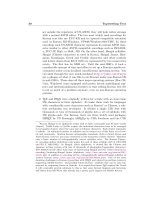
Along with the nonconditional branch, there are 8 conditional branch instructions
available in the PIC18 and they are shown in Fig. 7.54. They are branch on zero flag set
(bz), branch on zero flag reset (bnz), branch on carry flag set (bc), branch on carry
flag reset (bnc), branch on negative flag set (bn), branch on negative flag reset (bnn),
branch on overflow flag set (bov), and branch on overflow flag reset (bnov). These
instructions are equivalent to the branch on condition instructions found in other
processors.
These instructions behave similarly to the bra instruction except that they have
8 bits for the offset address (to the bra instruction’s 11). This gives the instructions
the ability to change the program counter by –64 to +63 instructions.
The last new feature of the PIC18 architecture that is different from the other archi-
tectures is the fast stack, in which WREG, STATUS, and BSR registers are saved non-
conditionally upon the interrupt acknowledge and vector jump and conditionally during
a subroutine call instruction. These registers can be optionally restored after a return
or retfie instruction.
Tables PIC18 tables are executed as:
TableRead:
movwf TableOff, 0
bcf STATUS, C, 0 ; First Calculate if past first 256
rlcf TableOff, w, 0 ; addresses and by how much
Program Memory
Register Space
PC
Program
Counter
Stack
ALU
Fast Stack
Instruction Register/
Decode
Second Instruction
Register
STATUS
WREG
BSR
FSR
File
Registers
Instruction Bit Pattern:
12345678 12345678
Instruction Operation:
BC/BNC: Branch on
Carry Flag
BN/BNN: Branch on
“N” Flag
BOV/BNOV: Branch on
“OV” Flag
BZ/BNZ: Branch on
Zero Flag
BRA: Branch
Allways
Flags Affected:
None
Instruction Cycl
es:
2 if Branch Taken
1 otherwise
Notes: Offset “n” is a
Two’s Complement
Number
BC 11000010 nnnnnnnn
12345678 12345678BNC 11100011 nnnnnnnn
12345678 12345678BN 11100110 nnnnnnnn
12345678 12345678BNN 11100011 nnnnnnnn
12345678 12345678BOV 11100100 nnnnnnnn
12345678 12345678BNOV 11100101 nnnnnnnn
12345678 12345678BZ 11100000 nnnnnnnn
12345678 12345678BNZ 11100001 nnnnnnnn
12345678 12345678BRA 11010nnn nnnnnnnn
Figure 7.54 The branch instruction can access addresses –512 to +511
instructions from the current program counter location.
Simpo PDF Merge and Split Unregistered Version -
370 USING THE PIC MCU INSTRUCTION SET
addlw Table & 0xFF
movf STATUS, w, 0
andlw 1
btfsc TableOff, 7, 0
addlw 1
addlw (Table >> 8) & 0xFF ; Add Offset to start of table to
movwf PCLATH, 0 ; PCLATH
movf STATUS, w, 0 ; If in Next Page, increment PCLATU
andlw 1
addlw UPPER Table
movwf PCLATU, 0
rlcf TableOff, w, 0 ; Calculate offset within 256 address
addlw LOW Table
movwf PCL, 0
Table:
dt
If the purpose of the computed goto is to return a byte value (using retlw), then
I would suggest taking advantage of the 16-bit instruction word, store 2 bytes in an
instruction word, and use the table read instructions to read back two values. This is some-
what more efficient in terms of coding and requires approximately the same number of
instructions and instruction cycles.
A computed byte table read (which allows compressed data) consists of the follow-
ing subroutine.
TableRead:
movwf TableOff
movlw LOW Table ; Calculate address
addwf TableOff, w, 0
movwf TBLPTRL, 0
movlw (Table >> 8) & 0xFF
btfsc STATUS, C, 0
addlw 1
movwf TBLPTRH, 0
movlw UPPER Table
btfsc STATUS, C, 0
addlw 1
movwf TBLPTRU, 0
TBLRD * ; Read byte at address
movf TABLAT, w, 0 ; Return the byte
return
Table:
db
Interrupts
When I show a basic interrupt handler for the mid-range PIC microcon-
trollers, along with the w and STATUS registers, I also include saving the contents of
the FSR and the PCLATH registers. This is not required in the PIC18 because of the
Simpo PDF Merge and Split Unregistered Version -
PIC18 INSTRUCTION SET 371
multiple FSR registers available and the ability to jump anywhere within the applica-
tion without using the PCLATH or PCLATU registers. If an FSR register is required
within an interrupt handler, chances are it can be reserved for this use within the appli-
cation when resources are allocated.
When a hardware interrupt request is acknowledged, the current WREG, STATUS,
and BSR are saved in the fast stack. The PCLATH (and PCLATU) registers should not
have to be saved in the interrupt handler unless a traditional table read (i.e., using a com-
puted goto) is implemented instead of a table read using the built-in instructions (and
shown in the previous section). The goto and branch instructions update the program
counter without accessing the PCLATH and PCLATU registers. These conditions will
allow a PIC18 interrupt handler with context saving to be as simple as:
org 8
Int
; #### - Execute Interrupt Handler Code
retfie 1
so long as nested interrupts are not allowed and subroutine calls do not use the fast stack.
PROCESSOR CONTROL INSTRUCTIONS
The PIC18Cxx has the same processor instructions as the other PIC microcontrollers,
but there is one instruction enhancement that I would like to bring to your attention. When
designing the PIC18Cxx, the Microchip designers did something I’ve wanted for years:
they created a nop instruction (Fig. 7.55) that has two bit patterns, all bits set and all
Program Memory
Register Space
Register Address Bus
PC
Program
Counter
Stack
ALU
Fast Stack
Instruction Register/
Decode
Second Instruction
Register
STATUS
WREG
BSR
FSR
File
Registers
Instruction Bit Pattern:
12345678 12345678
Instruction Operation:
Flags Affected:
None
Instruction Cycles:
1
Notes:There are two bit patterns for this
instruction
00000000 00000000
12345678 12345678
11111111 11111111
or:
Figure 7.55
The
nop
instruction is coded as either all bits set or
all bits reset.
Simpo PDF Merge and Split Unregistered Version -
372 USING THE PIC MCU INSTRUCTION SET
bits reset. The profoundness of this instruction and what can be done with it will prob-
ably not be immediately obvious to you.
In the PIC18, just the patch space instructions that are to be modified are changed
and no space is required for jumping around instructions. For the same example in the
PIC18, the patch space would be:
dw 0x0FFFF ; nop
dw 0x0FFFF ; nop
dw 0x0FFFF ; nop
dw 0x0FFFF ; nop
dw 0x0FFFF ; nop
dw 0x0FFFF ; nop
To add three instructions to the patch space, just the required changes for the three
instructions are made:
movf B, w, 0 ; Formerly “dw 0x0FFFF”
addwf C, w, 0 ; Formerly “dw 0x0FFFF”
movwf A, 0 ; Formerly “dw 0x0FFFF”
dw 0x0FFFF ; nop
dw 0x0FFFF ; nop
dw 0x0FFFF ; nop
Note that to add three instructions in this case, only three instructions of the patch
space are modified and there is no need for a goto instruction to jump around the unpro-
grammed addresses as you would for the low-end or mid-range PIC microcontroller
architectures.
Simpo PDF Merge and Split Unregistered Version -
373
8
ASSEMBLY-LANGUAGE SOFTWARE
TECHNIQUES
The PIC
®
microcontroller is an interesting device for which to write application software.
If you have experience with other processors, you probably will consider the PIC micro-
controller to be quite a bit different and perhaps even “low end” if you are experienced
with RISC processors. Despite this first impression, very sophisticated application soft-
ware can be written for the PIC microcontroller, and if you follow the tricks and sugges-
tions presented in this chapter, your software will be surprisingly efficient as well.
Much of the information I will give you in this book will leave you scratching your
head and asking, “How could somebody come up with that?” The answer often lies in
necessity—the application developer had to implement some features in fewer instruc-
tions, in fewer cycles, or using less variable memory (file registers in the PIC micro-
controller). For most of these programming tips, the person who came up with them not
only had the need to do them but also understood the PIC microcontroller architecture
and instruction set well enough to look for better ways to implement the functions than
the most obvious.
At the risk of sounding Zen, I want to say that the PIC microcontroller is best pro-
grammed when you are in the right “head space.” As you become more familiar with
the architecture, you will begin to see how to exploit the architecture and instruction-
set features to best implement your applications. The PIC microcontroller has been
designed to pass and manipulate bits and bytes very quickly between locations in the
chip. Being able to plan your applications with an understanding of the data paths in
mind will allow you to write applications that can require as little as one-third the clock
cycles and instructions that would be required in other microcontrollers. This level of
optimization is not a function of learning the instruction set and some rules. Instead, it
is a result of thoroughly understanding how the PIC microcontroller works and being
able to visualize the best path for data within the processor and have a feel for the data
flowing through the chip.
Copyright © 2008, 2002, 1997 by The McGraw-Hill Companies, Inc. Click here for terms of use.
Simpo PDF Merge and Split Unregistered Version -
374 ASSEMBLY-LANGUAGE SOFTWARE TECHNIQUES
Sample Template
When I am about to create my own mid-range PIC microcontroller applications, I
always start with the following template:
title “FileName—One Line Description”
#define _version “x.xx”
;
; Update History:
;
; Application Description/Comments
;
; Author
;
; Hardware Notes:
;
LIST R=DEC ; Device Specification
INCLUDE “p16cxx.inc” ; Include Files/Registers
; Variable Register Declarations
; Macros
__CONFIG _CP_OFF & _XT_OSC & _PWRTE_ON & _WDT_OFF & _BODEN_OFF
org 0
Mainline:
goto Mainline_Code
org 4 ; Interrupt Handler at Address 4
Int:
MainLine_Code:
; Subroutines
end
This template “structures” my applications and makes sure that I don’t forget any-
thing that I consider critical. The file template.asm can be found in the
Templates folder. Before starting any application, this file should be copied from
the subdirectory into the MPLAB IDE project, and the specifics for the application
should be added to it. When you are working with low-end or PIC18 chips, you can
use this template as a basis and modify it accordingly—looking over it, the only
change I would make to it for other PIC microcontroller processor architectures is
to delete or change the interrupt handler code because the vector at address 0x004
Simpo PDF Merge and Split Unregistered Version -
SAMPLE TEMPLATE 375
is specific to the mid-range chip. I first created this template around 1998, and it has
remained very constant over the years;I first started creating assembly-language
templates for IBM PC assembly-language programming, and this practice has served
me well with the PIC microcontroller as well as other devices.
The title and _version at the top of the file show what the application does so
that I can scan the files very quickly instead of going by what the file name indicates.
The title line will show up on the top of each new listing file page. The _version
define statement then will show the code revision level and can be inserted in any text
displayed by the application.
There may be a Debug define directive after the _version define directive if the
Debug label is going to be tested for in the application. This directive is used with
conditionally assembling code to take out long delays and hardware register opera-
tions that are not available within the MPLAB IDE simulator. Before building the
application for burning into a PIC microcontroller, the Debug define is changed so
that the “proper” code will be used with the application. Later in this book I will dis-
cuss the Debug defines in more detail and how they can help you with debugging your
application code.
Next, I put in a description of what the application does, along with its update his-
tory (with specific changes). One thing that I do that seems to be a bit unusual is that I
list the hardware operating parameters of the application. I started doing this so that I
could create stimulus files easily for applications. This seems to have grown into a
much more comprehensive list that provides a cross-reference between an application’s
hardware circuit and the PIC microcontroller software.
Before declaring anything myself, I load in the required include files and specify
that the default number type is to be decimal. As I will comment on elsewhere, I only
use the Microchip PIC microcontroller Include Files because these have all the
documented registers and bits of the data sheets, avoiding the need for me to create my
own. There are two points here that you should recognize are implemented to avoid
unnecessary work and possible errors. The first is specifying that numbers default to a
decimal radix to avoid having to continually convert decimal numbers to the normal hexa-
decimal default. The second is to only use Microchip-developed (or in the case of high
level languages, the compiler provided) chip register and constant include files to
avoid the possibility that I will mistype registers or constants that will leave me with
mistakes that are very hard to find later. It is interesting, but when I have worked with
teachers, they tend to have their students specify registers and constants in the program
and only work in hexadecimal; unfortunately, this causes a lot of problems that are very
difficult for the students (and the teachers helping them) to find because they are in areas
that are thought to be immune to errors). Another problem is that students, to avoid a
few keystrokes, will give registers different labels, which adds the task of cross-
referencing datasheet register names to the ones that the students have picked. I highly
recommend that you save yourself some mental effort and go with the register defini-
tions that are predefined by Microchip or the compiler vendor.
With the device declarations completed, I then do my variable, defines, and macro
declarations. When doing this, remember to always specify prerequisites before they are
used. The MPASM assembler will not be able to resolve any macro or define labels that
Simpo PDF Merge and Split Unregistered Version -
376 ASSEMBLY-LANGUAGE SOFTWARE TECHNIQUES
are defined after their first use. This is not true for labels that are referenced before their
use in the application instruction code that follows the declarations and operating
parameters.
Finally, I declare the device operating parameters that are to be programmed into the
CONFIGURATION register or CONFIGURATION fuses (which will be explained in
more detail later in this chapter) followed by the application code. I put subroutines at
the end of the application code simply because the reset and interrupt handler vectors
are at the “beginning” of the data space. Putting the subroutines after the mainline and
interrupt handler seems to be the most appropriate in this situation.
This template is used for single-source file applications, which make up the vast
majority of my PIC microcontroller applications. If multisource file applications are cre-
ated, then the __CONFIG line is left out of anything other than the first (or header) file,
which is explained elsewhere. Publics and externals are added in its place with
the code following as it does in the single-source file template. Variables should be
declared in the header file and then passed to the linked in files as publics.
This template can be modified and used with the other PIC microcontroller device
architectures.
Labels, Addresses, and Flags
If you have skipped ahead in this book and taken a look at some of the code examples
in the various chapters, you probably will be a bit concerned because there are a number
of different ways program addresses are used that probably won’t be familiar to you.
The PIC microcontroller’s architecture and instruction set require a more careful watch
of absolute addresses than you are probably used to when programming other devices.
In this section I want to discuss the different memory “spaces” in the PIC microcontroller,
what is stored in them, and how they are accessed.
The most familiar memory space to you is probably the instruction program memory.
As I said earlier in this book, the program memory is the width of the instruction word.
The maximum “depth” of the memory is based on the word size and can have the
instruction word size minus one for addressing for the low-end and mid-range PIC
microcontrollers. The PIC18 is a bit different because it expands on the concepts used
by the other architectures, allowing you to have a much larger program space.
To figure out the maximum depth of program memory in the low-end and mid-range
PIC microcontrollers, the formula
Maximum program memory = 2 ** (word size – 1)
is used. It is important to note that while the low-end, mid-range, and PIC18 program
counters are the size of the instruction word (12, 14, and 16 bits, respectively), the
upper half of the addressable space is not available to the application. This upper half
to the program memory is used for storing the configuration fuses, IDLOC nibbles, and
device identification bytes, as well as for providing test addresses used during PIC
Simpo PDF Merge and Split Unregistered Version -
LABELS, ADDRESSES, AND FLAGS 377
microcontroller manufacturing. The PIC18 architecture is the exception to the rule
because its configuration fuses can be accessed from the application using the table
read function.
When an application is executing, it can only jump with a set number of instructions,
which is known as the page. The page concept is discussed in more detail elsewhere in
the book. The size of the page in the various PIC microcontroller architecture families
is based on the maximum number of bits that could be put into an instruction for the
address. In the low-end PIC microcontroller, a maximum of 9 bits are available in the
goto instruction that is used to address a page of 512 instructions. In the mid-range
PIC microcontroller, the number of bits specified in goto is 11, for a page size of 2,048
instructions. The PIC18 can either branch relative to the current program counter value
or jump anywhere within the application without regard to page size.
The point of discussing this is to note that in these three families, addresses are
always absolute values within the current page. For example, if there was the code
org 0
goto Mainline
: ; Code to Skip Over
org 0x0123
Mainline:
the address value loaded into the goto instruction is an absolute address (given the label
Mainline), which is 0x0123. In other processors with which you may be familiar, an
offset would be added to the program counter, making the address in the goto instruc-
tion 0x0122 because the program counter had been incremented to the next instruction.
This can be further confused by an instruction sequence such as
btfsc Button, Down ; Wait for Button to be Pressed
goto $ - 1
The $ character returns a constant integer value that is the address of the instruction
where it is located. The goto $ - 1 instruction loads the address that is the address
of the goto $ - 1 instruction minus 1.
Further confusing the issue is how the PIC18 operates. The PIC18 microcontroller
processor behaves more like a traditional processor and has absolute address jumps and
relative address branches and does not have a page per se. The goto and call instruc-
tions in the PIC18 can change application execution anywhere within the PIC micro-
controller’s 1-MB program memory address range. Along with this, the PIC18 has the
ability to “branch” with an 8- or 11-bit two’s complement number. The branch instruc-
tions do not use an absolute address and instead add the two’s complement to the cur-
rent address plus two. In the PIC18, the instruction sequence
btfsc Button, Down, 1 ; Wait for Button to be Pressed
bra $ - (2 * 1)
Simpo PDF Merge and Split Unregistered Version -
378 ASSEMBLY-LANGUAGE SOFTWARE TECHNIQUES
would perform the same operation as the preceding example, but I replaced the goto
$ - 1 instruction with a “branch always.”
In the PIC18 example, if an odd address is specified, the MPLAB simulator will halt
without a message. If the code is burned into the PIC18 along with a jump to an odd
address, execution may branch to an unexpected address. As I noted earlier, each byte
is addressed in the PIC18 and not the word. Further complicating the use of relative jumps
is the instructions that take up more than one instruction word. These complexities lead
me to recommend that you do not use relative jumps with the $ character with the
PIC18 and instead use a define such as
#define CurIns(Offset) $+(2*Offset)
which would be inserted into the instruction sequence like
btfsc Button, Down, 1 ; Wait for Button to be Pressed
bra CurIns(-1)
and provide the same value as the original PIC18 example but eliminate the need for
you to create the formula for calculating the actual address. Offset in CurIns can
be a negative or positive value.
You probably will be comfortable with how the destination values for either the
goto and bra instructions are calculated depending on your previous experience. If
this is your first assembly-language experience, the absolute addresses of the low-end
and mid-range probably will make a lot of sense to you. If you have worked with other
processors before, the PIC18 will seem more familiar to you.
Regardless of which method is the most comfortable for you, I recommend writing
your applications in such a way that absolute addresses should not be a concern. This
means that labels should be used in your source code at all times, and the org direc-
tive statement is used only for the reset vector and interrupt vectors. For all other
addresses, the assembler should be used to calculate the absolute addresses for you. By
allowing the assembler to generate addresses, you will simplify your application coding
and make it much more “portable” to multiple locations within the same source file or
others.
For example, the mid-range code
org 0x012
btfsc Button, Down ; Address 0x012
goto 0x012 ; Address 0x013
will do everything that the preceding example code will do, but it is specific to one
address in the PIC microcontroller. By using the goto $ - 1 instruction, the code
can be “cut and pasted” anywhere within the application or used in other applications.
Letting the assembler generate the addresses for you is accomplished in one of two
ways. The first is the Label, which is placed in the first column of the source code and
should not be one of the reserved instructions or directives used by the assembler. In
the MPLAB assembler, a label is defined as any unknown string of characters. When
Simpo PDF Merge and Split Unregistered Version -
LABELS, ADDRESSES, AND FLAGS 379
one of these strings is encountered, it is loaded into a table along with the current pro-
gram counter value for when it is referenced elsewhere in the application.
Labels in MPLAB’s assembler can have a colon (:) optionally put on the end of
the string. To avoid any potential confusion regarding whether or not the label is to
be replaced with its address or is a define or macro, I recommend putting the colon
after it.
Using the example above, a Loop label can be added to make the code a bit more
portable:
Loop:
btfsc Button, Down ; Address = “Loop”
goto Loop ; Address = “Loop” + 1
The disadvantage of this method is that there can only be one Loop (and Skip) put
into an application. Program memory labels are really best suited for cases where they
can be more global in scope. For example, an application really should only have one
main Loop, and that is where this label should be used.
Personally, I always like to use the labels Loop, Skip, and End in my applica-
tions. To allow their use, I will usually preface them with something like the acronym
of the current subroutine’s name. For example, if the code was in the subroutine
GetButton, I would change it to
GB_Loop:
btfsc Button, Down ; Address = “Loop”
goto GB_Loop: ; Address = “Loop” + 1
Instead of using labels in program memory for simple loops, I prefer using the $ direc-
tive, which returns the current address of the program counter as an integer constant and
can be manipulated to point to the correct address. Going back to the original code for
the button poll snippet, the $ directive eliminates the need for a label altogether:
btfsc Button, Down ; Wait for Button to be Pressed
goto $ - 1
You do not have to expend the effort trying to come up with a unique label (which
can start becoming hard in a complex application), and as you get more comfortable
with the directive, you will see its what is happening faster than if a label were used.
The problem with using the $ directive is that it can be difficult to count out the offset
to the current instruction (either positive or negative). To avoid making mistakes in count-
ing, the $ should be done only in short sections of code, such as the one above, because
the destination offset to $ can be found. Also, beware of using the $ directive in large sec-
tions of code that has instructions added or deleted between the destination and the goto
instruction. The best way to avoid this is to use the $ only in situations such as the one
above, where code will not be added between the goto and the destination.
If you have worked with assemblers for other processors (Von Neumann), chances
are that you have had to request memory where variables were going to be placed. This
Simpo PDF Merge and Split Unregistered Version -
380 ASSEMBLY-LANGUAGE SOFTWARE TECHNIQUES
operation was a result of variable memory being in the same memory space as program
memory. This is not a requirement of the PIC microcontroller in which the register space
(where variables are located) is separate from the program memory space.
To allocate a variable in the PIC microcontroller, you have to specify the references
to a label to a file register address. In the first edition I specified that this was done by
finding the first file register in the processor and then starting a list of equates from there.
As discussed elsewhere, an equate is a directive that assigns a label a specific con-
stant value. Every time the label is encountered, the constant that is associated with it
is used. Program memory labels can be thought of as equates that have been given the
current value of the program counter.
For the PIC16F84, variable equate declarations for an application could look
like
i EQU 0x00C
j EQU 0x00D ; Note, “j” is Sixteen Bits in Size
k EQU 0x00F
:
The problems with this method are that adding and deleting variables are a problem—
especially if there are not very many free file registers available. To eliminate this prob-
lem, Microchip has come up with the CBLOCK directive that has a single parameter that
indicates the start of a label equate. Each label is given an ascending address, and if any
labels need more than 1 byte, a colon (:) and the number of bytes are added after the
label. When the definitions are finished, the ENDC directive is specified.
Using the CBLOCK and ENDC directives, the variable declarations above could be
implemented as
CBLOCK 0x00C ; Define the PIC16F84 File Register Start
i, j:2, k
ENDC
This is obviously much simpler than the previous method (i.e., it requires less thinking),
and it does not require you to change multiple values or specify a placeholder if one
address is deleted from the list.
What I don’t like about CBLOCK is that specific addresses cannot be specified within it.
For most variables, this is not a problem, but as I will indicate elsewhere in this book,
I tend to put variable arrays on power of 2 byte boundaries to take advantage of the PIC
microcontroller’s bit set/reset instructions to keep the index within the correct range.
To make sure that I don’t have a problem, I will specify an equate for the variable
array specifically and ensure that it does not conflict with the variables defined in the
CBLOCK.
The last type of data to define in the PIC microcontroller is the bit. If you look
through the Microchip MPLAB assembler documentation, you will discover that
there are no bit data types built in. This is not a significant problem if you are will-
ing to use the #define directive to create a define label that includes the register and
bit together.
Simpo PDF Merge and Split Unregistered Version -
SUBROUTINES WITH PARAMETER PASSING 381
For example, you could define the STATUS register’s zero flag as
#DEFINE zeroflag STATUS, Z
A define is like an equate except where the equate associates a constant to the
label, a define associates a string to the label. For the zeroflag define, if it were used
in the code
movf TMR0, f ; Wait for TMR0 to Overflow
btfss zeroflag
goto $ - 2
in the btfss instruction, the string STATUS, Z would replace zeroflag, as is shown
below when the application was assembled:
movf TMR0, f ; Wait for TMR0 to Overflow
btfss STATUS, Z
goto $ - 2
Defining bits like this is a very effective method of putting labels to bits. Using this
method, you no longer have to remember the register and bit number of a flag. This can
be particularly useful when you have a number of bits defined in a register (or multiple
registers). Instead of remembering the register and bit numbers for a specific flag, all
you have to remember is the define label. Using the bit define with the bit instruc-
tions of the PIC microcontroller allows you to work with single-bit variables in your
application.
Subroutines with Parameter Passing
For subroutines to work effectively, there must be the ability to pass data (known as
parameters) from the caller to the subroutine. There are three ways to pass parameters
in the PIC microcontroller, each with their own advantages and potential problems. The
first is to use global variables unique to each function, the second is to create a set of
variables that are shared between the functions, and the third is to implement a data stack.
Most high-performance computer systems have a stack for storing parameters (as well
as return addresses), but this feature is not built into the low-end and mid-range PIC
microcontrollers. In this section I want to introduce you to each of the three methods
and show how they can be implemented in the PIC microcontroller.
In most modern structured high level languages, parameters are passed to subroutines
as if they were parameters to a mathematical function. One value (or parameter) is
returned. An example subroutine (or function) that has data passed to it would look like
A = subroutine(parm1, parm2);
in C source code.
Simpo PDF Merge and Split Unregistered Version -
382 ASSEMBLY-LANGUAGE SOFTWARE TECHNIQUES
The subroutine’s input parameters (parm1 and parm2) and output parameter (which
is stored in A in the preceding above) can be shared and are common to the caller and
subroutine by the following methods:
1 Global variables
2 Unique shared variables
3 Data stack
Passing parameters using global variables really isn’t passing anything to a subrou-
tine and back. Instead, the variables, which can be accessed anywhere in the code, are
used by both the main line and the subroutine to call a subroutine that uses global vari-
ables. Just a call statement is used:
call subroutine
The advantage of this method is that it requires a minimal amount of amount of code
and executes in the least number of cycles. The problem with this method is that it does
not allow implementation of nested subroutines, and if you do want to have nested sub-
routines, you would have to copy one subroutine’s parameters into separate variables
before using the global variables for the nested subroutine call. This method cannot be
used for recursive subroutines, nor can it be used for interrupt handlers that may call
subroutines (or use the common global variables) that are already active. Despite these
drawbacks, this method of parameter passing is an excellent way for new-application
developers to pass subroutine and function parameters in assembly language because
it is so simple.
The second method is to use unique parameter variables for each subroutine.
Before the call, the unique variables are loaded with the input parameters, and after
the call, the returned parameter is taken from one of the variables. In this case, the
statement
A = subroutine(parm1, parm2);
can be implemented in assembler as
movf parm1, w ; Save Parameters
movwf subroutineparm1 ; passed to Subroutine
movf parm2, w
movwf subroutineparm2
call subroutine
movf subroutinereturn, w ; Get Returned
movwf A ; Parameter
This method allows nested subroutines to be implemented and even optimizes the
amount of variable space if the nested subroutine paths are plotted and the variables are
chosen in such a way that the variables passed in the different paths are not reused. As
with the global variable method, this method does not allow for calls from the interrupt
handler, nor does it allow for recursive code. Despite these drawbacks, this method is
Simpo PDF Merge and Split Unregistered Version -
SUBROUTINES WITH PARAMETER PASSING 383
often the preferred method of implementation because it is fast and very memory-
efficient.
The method normally used by most processors and high level languages is to save
parameters on a stack and then access the parameters from the stack. As indicated ear-
lier, the low-end and mid-range PIC microcontroller cannot access stack data directly,
but the FSR (INDEX) register offsets can be calculated easily. Before any subroutine
calls can take place, the FSR has to be offset with the start of a buffer:
movlw bufferstart – 1
movwf FSR
When the parameters are “pushed” onto the simulated stack, the operation is
incf FSR, f
movwf INDF
The increment of FSR is done first so that if an interrupt request is acknowledged during
this operation, any “pushes” in the interrupt handler will not affect the data in the
mainline.
“Popping” data from the stack uses the format
movf INDF , w
decf FSR, f
With the simulated stack, the example call to subroutine could use the code
movf parm1 , w ; Save Parameters
incf FSR, f
movwf INDF
movf parm 2, w
incf FSR, f
movwf INDF
incf FSR, f ; Make Space for Return
call subroutine
movf INDF, w ; Get Returned Value
decf FSR, f
movwf A
decf FSR, f ; Reset the STACK
decf FSR, f
This method is very good because it does not require global variables of any type and
allows for subroutines that are called from both the execution main line and the inter-
rupt handler or recursively. In addition, data on the stack can be changed (this opera-
tion has created “local” variables).
The disadvantage of this method is the complexity required for accessing data within
the subroutine and adding additional variables with low-end and mid-range PIC micro-
controllers. When accessing the variables and changing FSR, you will have to disable inter-
rupts. For the preceding example, to read parm1, the following code would have to used:
Simpo PDF Merge and Split Unregistered Version -
384 ASSEMBLY-LANGUAGE SOFTWARE TECHNIQUES
movlw 0 – 3
bcf INTCON, GIE
addwf FSR, f
movf INDF, w
movwf SUBRTN_TEMP ; Read “parm1”
movlw 3
bcf INTCON, GIE
addwf FSR, f
movf SUBRTN + TEMP, w
The SUBRTN_TEMP variable is used to save the value read from the stack while the
FSR is updated. For most changes in the FSR, simple increment and decrement instruc-
tions could be used instead and actually take fewer instructions and not require the
temporary variable. The preceding code could be rewritten as
bcf INTCON, GIE
decf FSR, f
decf FSR, f
decf FSR, f
movf INDF, w
incf FSR, f
incf FSR, f
incf FSR, f
bsf INTCON, GIE
While this code seems reasonably easy to work with, it does become a lot more com-
plex as you add 16-bit variables and arrays.
The PIC18 can be used effectively for passing parameters on a data stack created using
the FSR register and the POSTDEC# (where # is the FSR register from 0 to 2),
PREINC#, and PLUSW# INDF registers. These registers will maintain the stack for you
automatically and allow you to access data placed on the stack directly. To call a sub-
routine with two parameters and one returned, the following instructions could be used
(assuming that FSR0 is already set up to point to the data stack):
movff parm1, POSTDEC0 ; Save Parameters
movff parm2, POSTDEC0
decf FSR, f ; Make Space for Return
call subroutine
movff PREINC0, A ; Get Returned Value
incf FSR, f ; Reset the STACK
incf FSR, f
This is just over half the number of instructions required for the call in low-end and
mid-range devices. An even better improvement can be demonstrated reading param1,
which is 3 bytes down from the top of the stack:
movlw 3 ; Read “parm1”
movf PLUSW0, w
Simpo PDF Merge and Split Unregistered Version -
SUBTRACTION, COMPARING AND NEGATION 385
In these instructions, the byte that was pushed down onto the stack with 2 bytes on
top of it is accessed by adding three to the stack pointer and storing the value in the w
register (destroying the offset to the byte put there earlier). This capability makes the
PIC18 a very powerful architecture to work with and allows you and compiler writers
to develop code that is similar to what is used on high-end processors.
There is one method of passing parameters to and from that I haven’t discussed
because I do not believe that it is an appropriate method for the PIC microcontroller,
and that is using the processor’s registers to store parameters. For the PIC microcon-
troller, there is only the w register, which is 8 bits wide, that can be guaranteed for the
task. To frustrate using this method, the low-end devices’lack of a return instruction
prevents passing data back using the w register except in the case of using the retlw
instruction and a jump to a table offset. The zero, carry, and digit carry
STATUS register flags also could be used for this purpose, and they are quite effective
for being used as pass/fail return flags.
Subtraction, Comparing and Negation
This section was originally titled “Working with the Architecture’s Quirks” because there
are some unusual features about the architecture that make copying assembly-language
applications directly from another microcontroller to the PIC microcontroller difficult.
However, as I started listing what I wanted to do in this and the following sections, I
realized that there were many advantages to the PIC microcontroller’s architecture and
that many of the “quirks” actually allow very efficient code to be written for different
situations. In this and the following sections I will discuss how the PIC microcontroller
architecture can be used to produce some code that is best described as “funky.”
In addition, the basic operation sequence of adding two numbers together is
1 Load the accumulator with the first additional RAM.
2 Add the second additional RAM to the contents of the accumulator.
3 Store the contents of the accumulator into the destination.
In PIC microcontroller assembly language code, this is
movf Parm1, w
addwf Parm2, w
movwf Destination
If it’s required, the movf and addwf instructions can be changed to movlw or
addlw, respectively, if either parameter is a constant.
Subtraction in the PIC microcontroller follows a similar set of instructions, but
because of the way the subtraction operation works, the subtracted value must be loaded
first into the accumulator. For example, for the high level language statement
Destination = Parm1 – Parm2
Simpo PDF Merge and Split Unregistered Version -
386 ASSEMBLY-LANGUAGE SOFTWARE TECHNIQUES
the sequence of operations is
1 Load the w register with the second parameter (which is the value to be taken away
from the first).
2 Subtract the contents of the w register from the first parameter and store the result
in the w register.
3 Store the contents of the w register in the destination.
In PIC microcontroller assembly code, this is
movf Parm2, w
subwf Parm1, w
movwf Destination
As with the addition operation, the movf and subwf instructions can be replaced with
movlw or sublw, respectively, if either Parm1 or Parm2 is a constant.
The PIC microcontroller’s instructions contrasts with those of the 8051 and other
microcontroller architectures, in which the subtract instruction takes away the
parameter value from the contents of the accumulator. As I have indicated elsewhere,
the PIC microcontroller subtract instruction actually works as
PIC microcontroller subtract = parameter – w
= parameter + (w ^ 0x0FF) +1
This operation affects the zero, carry, and digit carry STATUS register flags. In most
applications, it is how the carry flag is affected that is of the most importance. This flag
will be set if the result is equal to or greater than zero. This is in contrast to how the
carry and borrow flags work in most processors. I have described the carry flag after
a subtract operation as a “positive flag.” If the carry flag is set after a subtract opera-
tion, then a borrow of the next significant byte is not required. It also means that the
result is negative if the carry flag is reset.
This can be seen in more detail by evaluating the subtract instruction sequence
for
Result A – B
which is
movlw B ; Assume A and B are Constants
sublw A
movwf Result
By starting with A equals to 1, different values of B can be used with this sequence to
show how the carry flag is set after subtract instructions. Table 8.1 shows the result,
carry, and zero flags after the snippet above.
I did not include the digit carry (DC) flag in the table because it will be the same as
carry for this example. In subtraction of more complex numbers (i.e., two-digit hex),
Simpo PDF Merge and Split Unregistered Version -
SUBTRACTION, COMPARING AND NEGATION 387
the DC flag becomes difficult to work with, and specific examples for its use (such as
the ASCII-to-nybble conversion routines) have to be designed.
When you are first learning how to program in assembly language, you may want to
convert high level language statements into assembly language using formulas or basic
guides. When you look at subtraction for comparing, the code seems very complex. In
actuality, using the PIC microcontroller subtract instruction isn’t that complex, and
the instruction sequence
movf Parm1, w/movlw Parm1
subwf Parm2, w/sublw Parm2
btfsc status, C
goto label
can be used each time the statement
if (A Cond B) then go to label
is required, where Cond is one of the values specified in Table 8.2.
By selecting a STATUS flag (carry on zero) to test, the execution of the goto instruc-
tion can be specified, providing you with a simple way of implementing the conditional
jumps using the code listed in Table 8.3.
TABLE 8.1 SUBTRACTION CARRY AND
ZERO FLAG RESULTS
AB RESULT CARRY ZERO
10 1 1 0
11 0 1 1
1 2 0x0FF(–1) 0 0
TABLE 8.2 if CONDITION DEFINITIONS
CONDITION OPERATION
== Jump if equal
!= Jump if not equal
> Jump if FIRST is greater than the second
>= Jump if FIRST is greater than or equal to the second
< Jump if FIRST is less than the second
<= Jump if FIRST is less than or equal to the second
Simpo PDF Merge and Split Unregistered Version -