PROGRAMMING AND CUSTOMIZING THE PIC MICROCONTROLLER 3rd phần 6 pdf
Bạn đang xem bản rút gọn của tài liệu. Xem và tải ngay bản đầy đủ của tài liệu tại đây (1.37 MB, 130 trang )
MID-RANGE BUILT-IN EEPROM/FLASH ACCESS 623
may be accessed incorrectly, causing problems with subsequent reads. You should never
use the instruction
clrf GPIO
Data is written to the most significant bit first, which is probably backwards to most
applications. Before any transfer, a control byte has to be written. The control byte data
is in the format
0b1010000R
where R is the Read/_Write byte (indicating what is coming next). If this bit is set,
then a read of the EEPROM at the current address pointer will take place. If a write is
to take place, the read/write bit is reset.
After a byte is sent, the SDA line is pulled low to indicate an acknowledgment (ACK
or just A in the bitstream representations below). This bit is set low (as an acknowl-
edgment) when the operation has completed successfully. If the acknowledgment bit is
high (NACK), it does not necessarily mean there was a failure; if it is issued by the
EEPROM, then it indicates a previous write has not completed. The PIC microcontroller
will issue the acknowledgment to stop the EEPROM from preparing to send additional
bytes out of its memory in a multibyte read.
There are five operations that can be carried out with the EEPROM that is built into
the PIC12CE5xx. They are
1 Current address set
2 Current address set/data byte write
3 Data byte read at current address
4 Sequential (multibyte) read at current address
5 Write completion poll
The EEPROM in the PIC12CE5xx is only 16 bytes in size. Each byte is accessed using
a 4-bit address. This address is set using a control byte, with the R bit reset followed by
the address. The bitstream looks like this:
idle – Start – 1010000A – 0000addrA – DataByteA – Stop - idle
In the second byte sent, the 0b00000addr pattern indicates that the four addr
address bits become the address to set the EEPROM’s internal address pointer to for
subsequent operations.
After the 2 bytes have been sent, the SCL and SDA lines are returned to IDLE for
three cycles using the instruction
movlw 0xC0
iorwf GPIO, f ; set SDA /SCL
before another operation can complete.
Simpo PDF Merge and Split Unregistered Version -
624 PIC MCU OPTIONAL HARDWARE FEATURES
The address data write is similar to the address write but does not force the two lines
into IDLE mode, and it passes along a data byte before stopping the transfer:
Idle – Start – 10100000A – 0000addrA – DataByteA – Stop - idle
Data bytes can be read singly or sequentially depending on the state of ACK from the
PIC microcontroller to the EEPROM after reading a byte. To halt a read, when the last
byte to be read has been received, the PIC microcontroller issues a NACK (or N in the
bitstream listing) to indicate that the operation has completed.
A single-byte read looks like this:
idle – Start – 10100001A – DataByteN – Stop – idle
whereas a 2-byte read looks like this:
idle – Start – 10100001A – DataByteA – DataByteN – Stop - idle
The last operation is sending dummy write control bytes to poll the EEPROM to see
whether or not a byte write has completed (10 ms is required). If the write has completed,
then an ACK will be returned; otherwise, a NACK will be returned.
This is a pretty cursory explanation of how the PIC12CE5xx’s built-in EEPROM
works. In later chapters I will include a more comprehensive explanation of accessing
I2C and provide you with code examples to do it.
I do want to make one point on the flash15x-ASM code you will see referenced in
the 12CE5xx datasheet and on the Microchip web page. This file is designed to be
linked into your application and provide the necessary I2C routines to access the
EEPROM memory. Unfortunately, this file is quite difficult to set up correctly, and
there are no instructions for using it.
If you do want to use the flash15x.ASM file, then there are a few things to do:
1 Install it so that it occupies memory in the first 256 bytes of the PIC microcontroller.
The file should not be put at the start of program memory because this will interfere
with the PIC microcontroller’s reset.
2 Declare EEADDR and EEDATA in your file register variable declarations.
3 Make sure that the #define emulated line is commented out. If this line is left
in, code will be generated that will attempt to write to the SDA and SCL bits (which
don’t exist) and in the process will set all the GPIO bits to output.
TMR1
Along with TMR0, many PIC microcontrollers have an additional 16-bit (TMR1) and
8-bit (TMR2) timer built into them. These timers are designed to work with the compare/
capture program hardware feature. Along with enhancing this module, they also can be
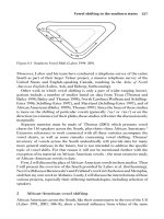
used as straight timers within the application. TMR1 (Fig. 16.3 shows the block diagram
Simpo PDF Merge and Split Unregistered Version -
TMR1 625
of the timer) is a 16-bit timer that has four possible inputs. What is most interesting about
TMR1 is that it can use its own crystal to clock the timer. This allows TMR1 to run while
the PIC microcontroller’s processor is “asleep.”
To access TMR1 data, the TMR1L and TMR1H registers are read and written. Just
as in TMR0, if the TMR1 value registers are written, the TMR1 prescaler is reset. A
TMR1 interrupt request (TMR1IF) is made when TMR1 overflows. TMR1 interrupt
requests are passed to the PIC microcontroller’s processor when the TMR1IE bit is set.
TMR1IF and TMR1IE normally are located in the PIR and PIE registers. To request
an interrupt, along with TMR1IE and GIE being set, the INTCON PIE bit also must be
set. To control the operation of TMR1, the T1CON register is accessed with its bits
defined as shown in Table 16.2.
The external oscillator is designed for fairly low-speed real-time clock applications.
Normally, a 32.768-kHz watch crystal is used, along with two 33-pF capacitors. Additionally,
T1OSCO
T1OSCI
T1OSCEN
TMR1CS
T1CKPS1:
T1CKPS0
Synch
_T1SYNCH
TMR1ON
TMR1L TMR1H
TMR1IF
TMR1IE
TMR1
Interrupt
Request
1
0
FOsc/4
Timer1
Prescaler
1
0
OF
Figure 16.3 TMR1 block diagram.
TABLE 16.2 T1CON REGISTER BIT DEFINITION
BIT DESCRIPTION
7–6 Unused
5–4 T1CPS1–T1CPS0—Select TMR1 prescaler value
11—1:8 prescaler
10—1:4 prescaler
01—1:2 prescaler
00—1:1 prescaler
3 T10SLEN—Set to enable TMR1’s built-in oscillator.
2 T1SYNCH—When TMR1CS is reset, the MR1
clock is synchronized to the instruction clock.
1 TMR1CS—When set, external clock is used.
0 TMR1ON—When set, TMR1 is enabled.
Simpo PDF Merge and Split Unregistered Version -
626 PIC MCU OPTIONAL HARDWARE FEATURES
100- or 200-kHz crystals could be used with TMR1, but the capacitance required for the
circuit changes to 15 pF. The TMR1 oscillator circuit is shown in Fig. 16.4.
When TMR1 is running at the same time as the processor, the T1SYNCH bit should
be reset. This bit will cause TMR1 to be synchronized with the instruction clock. If the
TMR1 registers are to be accessed during processor execution, resetting T1SYNCH will
make sure that there are no clock transitions during TMR1 access. T1SYNCH must be
set (no synchronized input) when the PIC microcontroller is in sleep mode. In sleep
mode, the main oscillator is stopped, stopping the synchronization clock to TMR1.
In the PIC18 devices, TMR1 can be specified as the processor clock. This feature is
one way to implement a low-current operating mode (the PIC microcontroller will run
while drawing less than 1 mA of current) without disabling the entire device and its built-
in functions. Note that returning to the normal program oscillator will require the
1024-instruction-cycle and optional 72-ms power-up reset delay that occurs when the
PIC microcontroller clock starts up.
The TMR1 prescaler allows 24-bit instruction cycle delay values to be used with
TMR1. These delays can be either a constant value or an overflow, similar to TMR0.
To calculate a delay, the formula
Delay = (65,536 – TMR1Init) x prescaler / T1frequency
is used, where the T1frequency can be the instruction clock, TMR1 oscillator, or an
external clock driving TMR1. Rearranging the formula, the TMR1init initial value can
be calculated as
TMR1Init = 65,536 – (Delay x T1Frequency / prescaler)
When calculating delays, the prescaler will have to be increased until the calculated
TMR1Init is positive—this is similar as to how the TMR0 prescaler and initial value
are calculated for TMR0.
TMR2
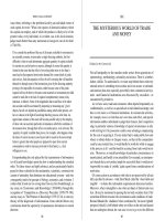
TMR2 is used as a recurring event timer (see Fig. 16.5). When it is used with the CCP
module, it is used to provide a PWM timebase frequency. In normal operations, it can
be used to create a 16-bit instruction cycle delay.
T1OSCO
T1OSCI
Crystal
Cext
Figure 16.4 TMR1 can be driven by its
own separate 32.768-kHz oscillator.
Simpo PDF Merge and Split Unregistered Version -
TMR2 627
TMR2 is continually compared against the value in PR2. When the contents of TMR2
and PR2 match, TMR2 is reset, and the event is passed to the CCP as TMR2 Reset.
If the TMR2 is to be used to produce a delay within the application, a postscaler is incre-
mented when TMR2 overflows and eventually passes an interrupt request to the
processor. TMR2 is controlled by the T2CON register, which is defined in Table 16.3.
The TMR2 register can be read or written at any time with the usual note that writes
cause the prescaler and postscaler to be zeroed. Updates to T2CON do not affect the
TMR2 prescaler or postscaler.
The timer itself is not synchronized with the instruction clock like TMR0 and TMR1
because it can be used only with the instruction clock. This means that TMR2 can be
incremented on a 1:1 instruction clock ratio.
PR2 contains the reset, or count up to value. The delay before reset is defined as
Delay = prescaler x (PR2 + 1) / (Fosc / 4)
TMR1IF
TMR2ON
FOsc/4
TMR2
Prescaler
T2CKPS1:
T2CKPS0
TMR2
Reset
Comparator
PR2
A == B
TMR2
Postscaler
TOUTPS2:
TOUTPS0
Figure 16.5 TMR2 block diagram.
TABLE 16.3 T2CON REGISTER BIT DEFINITION
BIT DESCRIPTION
7 Unused
6–5 TOUTPS3–TOUTPS0—TMR2 postscaler select
1111—16:1 postscaler
1110—15:1 postscaler
.
.
.
0000—1:1 postcaler
2 TMR2ON—When set, TMR2 is enabled
1–0 T2CKPS—TMR2 prescaler selection bits
1x—16:1 prescaler
01—4:1 prescaler
00—1:1 prescaler
Simpo PDF Merge and Split Unregistered Version -
628 PIC MCU OPTIONAL HARDWARE FEATURES
If PR2 is equal to zero, the delay is
Delay = (prescaler x 256) / (Fosc / 4)
I do not usually calculate TMR2 delays with an initial TMR2INIT value. Instead, I
take advantage of the PR2 register to provide a repeating delay and just reset TMR2
before starting the delay.
To calculate the delay between TMR2 overflows (and interrupt requests), the following
formula is used:
Delay = (prescaler x [PR2 + 1|256]) /((Fosc / 4) x postscaler)
Interrupts use the TMR2IE and TMR2IF bits that are similar to the correspon-
ding bits in TMR1. These bits are located in the PIR and PIE registers. Because of
the exact interrupt frequency, TMR2 is well suited for applications that provide “bit
banging” functions such as asynchronous serial communications and PWM signal
outputs.
Compare/Capture/
PWM (CCP) Module
Included with TMR1 and TMR2 is a control register and a set of logic functions (known
as the CCP) that enhances the operation of the timers and can simplify your applica-
tions. This hardware may be provided singly or in pairs, which allows multiple func-
tions to execute at the same time. If two CCP modules are built into the PIC
microcontroller, then one is known as CCP1 and the other as CCP2. In the case where
two CCP modules are built in, then all the registers are identified with the CCP1 or CCP2
prefix. The CCP hardware is controlled by the CCP1CON (or CCP2CON) register,
which is defined in Table 16.4.
The most basic CCP mode is capture, which loads the CCPR registers (CCPR14,
CCPR1C, CCPR2H, and CCPR2L) according to the mode the CCP register is set in.
This function is illustrated in Fig. 16.6 and shows that the current TMR1 value is saved
when the specified compare condition is met.
Before enabling the capture mode, TMR1 must be enabled (usually running with
the PIC microcontroller clock). The “edge detect” circuit in the figure is a 4:1 multi-
plexor, which chooses between the prescaled rising-edge input or a falling-edge input
and passes the selected edge to latch the current TMR1 value and optionally request
an interrupt.
In capture mode, TMR1 is running continuously and is loaded when the condition
on the CCPx pin matches the condition specified by the CCPxMS:CCPxM0 bits. When
a capture occurs, then an interrupt request is made. This interrupt request should be
acknowledged and the contents of CCPRxH and CCPRxL saved to avoid having them
written over and the value in them lost.
Simpo PDF Merge and Split Unregistered Version -
COMPARE/CAPTURE/PWM (CCP) MODULE 629
TABLE 16.4 CCPXCON REGISTER BIT DEFINITIONS
BIT FUNCTION
7–6 Unused
5–4 DC1B1–DC1B0—CEPST significant 2 bits of the PWM compare value.
3–0 CCP1M3–CCP1M0—CCP module operating mode
11xx—PWM mode
1011—Compare mode, trigger special event
1010—Compare mode, generate software interrupt
1001—Compare mode, on match, CCP pin low
1000—Compare mode, on match, CCP pin high
0111—Capture on every sixteenth rising edge
0110—Capture on every fourth rising edge
0101—Capture on every rising edge
0100—Capture on every falling edge
00xx—CCP off
CCP1
Pin
Prescaler
Edge Detect
1:11:41:16
CCP
Interrupt
Request
CCPR1H
CCPR1L
TMR1H TMR1L
CCP1M3:CCP1M0
Figure 16.6 Block diagram of CCP capture circuitry.
Capture mode is used to time-repeating functions or in determining the length of a
PWM pulse. If a PWM pulse is to be timed, then when the start value is loaded, the
polarity is reversed to get to the end of the pulse. When timing a PWM pulse, the TMR1
clock must be fast enough to get a meaningful value with a high enough resolution that
there will be an accurate representation of the timing.
Compare mode changes the state of the CCPx pin of the PIC microcontroller when
the contents of TMR1 match the value in the CCPRxM and CCPRxL registers as
shown in Fig. 16.7. This mode is used to trigger or control external hardware after a
specific delay.
Simpo PDF Merge and Split Unregistered Version -
630 PIC MCU OPTIONAL HARDWARE FEATURES
The most interesting use I’ve seen for the compare mode of the CCP is to turn the
PIC microcontroller into a “watchdog” for a complex system. As is shown in Fig. 16.8,
the PIC microcontroller controls reset to the system processor. On power-up, the PIC
microcontroller holds the processor reset until Vcc has stabilized, and then the TMR1
is reset each time the system writes to the PIC microcontroller. System reset is enabled
if after a time-out delay Vcc falls below a specific level.
Using event-driven code, the PIC microcontroller application would look like this:
PowerUpEvent() // PIC microcontroller Power Up
{
TMR1 = 0; TMR1 = on; // Start TMR1
CCPRx = PowerUpDelay; // Put in Watchdog Delay
CCPxCON = 0b000001000; // Drive Pin Low and /then High
// on Compare Match
ADCIE = on; // Start ADC Check of Vcc
} // End PowerUpEvent
CompareMatchEvent( ) // TMR1 = Compare / WDT T/O.
{
CCP2
Pin
CCPR1H CCPR1L
TMR1H TMR1L
Comparator
O/P
Select
CCP2M3:CCP2M0
CCP2IF
Figure 16.7 Block diagram of CCP compare
circuitry.
PC System
Processor
PIC Micro
ADx
PSP
CCPx
IDE Bus
Reset
V
cc
Figure 16.8 PC watchdog timer using PIC
microcontroller with the CCP compare circuitry
enabled.
Simpo PDF Merge and Split Unregistered Version -
COMPARE/CAPTURE/PWM (CCP) MODULE 631
CCPxCON = 0; // Turn off compare.
CCPx = 1; // Reset system
} // End CompareMatchEvent
PSPWriteEvent( ) // PSP Written to Reset WDT
{ // Count
TMR1 = 0;
} // End PSPWriteEvent
ADCIFEvent() // ADC Finished Vcc check
{
if (ADC < OperatingMinimum) {
CCPxCON = 0; // Turn Off ADC
CCPx = high; // Reset system program
}
ADCIF = 0; // Reset Interrupt Request
} // End ADCIFEvent
PWM OPERATION
Of the three CCP modes, I find the PWM signal generator to be the most useful. This
mode outputs a PWM signal using the TMR2 reset at a specific value capability. The
block diagram of PWM mode is shown in Fig. 16.9. The mode is a combination of the
normal execution of TMR2 and capture mode; the standard TMR2 provides the PWM
period, whereas the compare control provides the “on” time specification.
When the PWM circuit executes, TMR1 counts until its most significant 8 bits are equal
to the contents of PR2. When TMR2 equals PR2, TMR2 is reset to 0, and the CCPx pin is
set high. TMR2 is run in a 10-bit mode (the 4:1 prescaler is enabled before PWM opera-
tion). This 10-bit value is then compared with a program value in CCPRxM (along with the
two DCxBx bits in CCPxCON), and when they match, the CCPx output pin is reset low.
To set up a 65 percent duty cycle in a 20-kHz PWM executing in a PIC microcontroller
clocked at 4 MHz, the following steps are taken: First, the CCPRxM and PR2 values are
calculated for TMR2; the 4:1 prescaler must be enabled, resulting in a delay of
Delay = (PR2 + 1) *4 / (frequency/4)
PR2 = delay * frequency – 1
= 50msec * 4mHz – 1
= 200 – 1
= 199
Simpo PDF Merge and Split Unregistered Version -
632 PIC MCU OPTIONAL HARDWARE FEATURES
Then, 65 percent of 200 is 130, which is loaded into CCPRxM.
The code for creating the 65 percent 20-kHz PWM is
movlw 199
movwf PR2 ; Set up TMR2 Operation
movlw (1 << TMR2on) + 1
movwf T2CON ; Start it Running with a 50 msec
; Period
movlw 130 ; 65% of the Period
movwf CCPRxH
movlw (1<<DCxB1) + 0x00F
movwf CCPxCON ; Start PWM
; PWM is operating
Note that in this code I don’t enable interrupts or have to monitor the signal output.
In addition, you should notice that I don’t use the fractional bits. To use the 2 least
significant bits, I assume that they are fractional values. For the preceding example,
if I wanted to fine-tune the PWM frequency to 65.875 percent, I would recalculate
the value as a fraction of the total period.
For a period of 200 TMR2 counts with a prescaler of 4, the CCPRxH value
becomes 131.75. To operate the PWM, I would load 130 into CCPRxh (subtracting
1 to match TMR2’s zero start) and then the fractional value 0.75 into DCxB1 and
DCxB0 bits. I assume that DCxB1 has a value of 0.50 and that DCxB0 has a frac-
tional value of 0.25. Thus, to get a PWM in this case, CCPRxH is loaded with 130,
and DCxB1 and DCxB0 are both set. Table 16.5 gives the fractional DCxBX bit
values.
CCPx
Pin
CCPRxH
TMR2
Comparator
DCxB1:
DCxB0
Prescaler
Comparator
PR2
A
B
A
B
A > B
A == B
R
S
Q
Reset
Figure 16.9 CCP PWM generation circuitry block
diagram.
Simpo PDF Merge and Split Unregistered Version -
SERIAL I/O 633
The least significant 2 bits of the PWM obviously are not that important unless a very
small PWM “on” period is used in an application. A good example of this is using the
PWM module for an R/C servo. In this case, the PWM period is 20 ms with an “on”
time of 1 to 2 ms. This gives a PWM pulse range of 5 to 10 percent, which makes the
DCxB1 and DCxB0 bits important in positioning the servo accurately.
Serial I/O
As with many microcontrollers, the PIC microcontroller has optional built-in serial I/O
interfacing hardware. These interfaces, which are available on certain PIC microcon-
troller part numbers, allow a PIC microcontroller to interface with external memory and
enhanced I/O functions (such as ADCs) or communicate with a PC using RS-232. As with
other enhanced peripheral features, the serial I/O hardware is available on different PIC
microcontrollers, and the hardware may be available differently in different devices.
SYNCHRONOUS SERIAL PORT (SSP)
COMMUNICATIONS MODULE
In discussing the synchronous serial port (SSP), I am first going to discuss its basic oper-
ations, followed by the I2C operations in the next section. There are two reasons why
I break operation of the SSP into two parts, the first being that I2C is quite a complex
operation that I feel would be best served by a discussion in its own section.
The second reason for splitting out the I2C function is the inability of two SSI
versions to provide the full range of I2C operations. The SSP and BSSP modules,
which are available in many PIC microcontroller part numbers, do not have I2C
master mode capabilities. This limits their usefulness in working with I2C (where
typically the PIC microcontroller is a master) as compared with PIC microcon-
trollers equipped with the MSSP (master SSP) module, which does have I2C mul-
timaster capabilities.
SPI (its data stream is shown in Fig. 16.10) is an 8-bit synchronous serial protocol
that uses 3 data bits to interface with external devices. Data is clocked out, with the most
TABLE 16.5 CCP DCXBX BIT DEFINITION
FRACTION DCXB1–DCXB0
0.00 00
0.25 01
0.50 10
0.75 11
Simpo PDF Merge and Split Unregistered Version -
634 PIC MCU OPTIONAL HARDWARE FEATURES
significant bit first, on rising or falling edges of the clock. The clock itself is generated
within the PIC microcontroller (master mode), or it is provided by an external device
and used by the PIC microcontroller (slave mode) to clock out the data.
The clock can be positive, as shown in the figure with a 0 idle or negative (high line
idle) with a 1 idle and the clock pulsing to 0 and back again. The data receive latch is
generally on the return to idle state transition.
The BSSP module is the basic SSP module and provides data pulling on the return
to idle clock edge. The original SSP module provides the ability to vary when data is
output and read.
Controlling the operation of the different SSP modules is the SSPCON register. In
describing the operational bits, note that I only describe the SPI-specific operations in
Table 16.6.
Clock
Data
“Line”
Idle
“Line”
Idle
Bit 6Bit 7 Bit 5 Bit 4 Bit 3 Bit 2 Bit 1 Bit 0
TABLE 16.6 SSP/BSSP SSPCON REGISTER BIT DEFINITION
BIT FUNCTION
7 WCOL—Write collision, set when new byte written to SSPBUF
while transfer is taking place.
6 SSPOV—Receive overflow, indicates that the unread byte is
SSPBUF overwritten while in SPI slave mode.
5 SSPEN—Set to enable the SSP module.
4 CKP—Clock polarity select, set to have a high idle.
3–0 SSPM3–SSPMO—SPI mode select
1xxx—I2C and reserved modes
011x—I2C slave modes
0101—SPI slave mode, clock = SCK pin, _SS not used
0100—SPI slave mode, clock = SCK pin, _SS enabled
0011—SPI master mode, TMR2 clock used
0010—SPI master mode, INSCK/16
0001—SPI master mode, INSCK/4
0000—SPI master mode, INSCK
Figure 16.10 SPI data and clock waveform.
Simpo PDF Merge and Split Unregistered Version -
SERIAL I/O 635
The block diagram for the SSP module is shown in Fig. 16.11. In master mode, when
a byte is written to SSPBUF, an 8-bit most-significant-bit-first data transfer process is
initiated. The status of the transfer can be checked by the SSPSTAT register BF flag;
the SSPSTAT register is defined as shown in Table 16.7.
The connection of a PIC microcontroller to an SPI bus is quite straightforward.
In Fig. 16.11, two PIC microcontrollers are shown with the SDO and SDI sides con-
nected. To initiate a byte transfer, a byte is written to the SSPBUF of the master.
Writing to the SSPBUF of the slave will not initiate a transfer. When SPI mode is
enabled, the SDI, SDO, and SCK bits’ TRIS functions are set appropriately. This is
shown in Fig. 16.12.
The SSP SPI transfers can be used for single-byte synchronous serial transmits of
receivers with serial devices. In Fig. 16.13 I show the circuit to TX a byte to a 74LS374
Instruction
Clock
TMR2
_SS
SCK
SDO
Prescaler
Edge
Select
Clock
SSPBUF
SDI
Reset
Reset
Figure 16.11 Block diagram of SSP SPI module.
TABLE 16.7 SSP/BSSP SSPSTAT BIT DEFINITION
BIT FUNCTION
7 SMP—Set to have data sampled after active to
idle transition; reset to sample at active-to-idle
transition; not available in BSSP.
6 CKE—Set to TX data on idle-to-active transition;
else TX data on active-to-idle transition; not
available in BSSP
5 D/_A—Used by I2C.
4 P—Used by I2C.
3 S—Used by I2C.
2 R/_W—Used by I2C.
1 UA—Used by I2C.
0 BF—Busy flag, reset while SPI operation active.
Simpo PDF Merge and Split Unregistered Version -
636 PIC MCU OPTIONAL HARDWARE FEATURES
wired as a serial in, parallel out shift register. In Fig. 16.14. I show a 74LS374 being
used with a 74LS244 as a synchronous parallel in, serial out register. Both these oper-
ations are initiated by a write to SSPBUF.
The SPI data receive operation may be immediately obvious. To latch data into the
74LS374, the I/O pin is driven high; this disables the 74LS374’s drivers, allowing the
parallel data to be latched in. When the I/O pin is low, the 74LS244’s drivers are dis-
abled, and the 74LS374 behaves like a shift register.
Figure 16.12 SPI master/slave connection.
PIC Micro
‘374
SDO
SCK
_OE
1Q
1D
2Q
2D
3Q
7D
Bit 0
Bit 1
Bit 7
Figure 16.13 Wiring connection to pass SPI data from
the PIC microcontroller to a serial-to-parallel converter.
Simpo PDF Merge and Split Unregistered Version -
SERIAL I/O 637
To show this, here is some code to read the input state of Fig. 16.14. Note that I dis-
able the SSPEN bit when a transfer is not taking place to allow the I/O pin and SCK to
strobe in the data.
bsf IOPin ; Want to Latch Data into the ‘374
bcf SCK
bsf STATUS, RPO
bcf IOpin
bcf SCK
bcf STATUS, RP0
bsf SCK ; Latch the Data into the ‘374
bcf SCK
bcf IOpin ; Disable ‘244 output, Enable ‘374
movlw (I << SMP) + (I << CKE)
movwf SSPSTAT ; Set up the SSP Shift In
movlw (I << SSPEN) + (I << CKP) +0x000
movwf SSPCON
movf TXData, f ; Load the Byte to Send
movwf SSPBUF ; Start Data Transfer
btfss SSPTAT, BF
goto $ - 1 ; Wait for Data Receive to Complete
; Data Ready in SSPBUF when Execution
; Here
bcf SSPCON, SSPEN ; Turn off SSP
When using the SSP, the data rate either can be selected as a multiple of the execut-
ing clock or use the TMR2 overflow output. The actual timing depends on the hardware
the PIC microcontroller SSP master is communicating with.
PIC Micro
‘374
SDI
SCK
_OE
7D
1Q
1D
2Q
Bit 0
Bit 1
Bit 7
I/O
6D
7Q
_OE
‘244
Figure 16.14 Wiring to bring data from a parallel-to-serial
converter into a PIC microcontroller.
Simpo PDF Merge and Split Unregistered Version -
638 PIC MCU OPTIONAL HARDWARE FEATURES
When in slave mode, along with an external clock being provided, there is a trans-
mit reset pin known as _SS. When this pin is asserted high, the SSP output is stopped
(the SDO TRIS bit is changed to input mode), and the SSP is reset with a count of zero.
When the bit is reset, the clock will start up again, and the original most significant bit
is reset, followed by the remaining 7 bits.
MASTER SSP AND I2C OPERATION
When I wrote the first edition of this book, one of the most significant concerns people had
with the PIC microcontroller’s built-in hardware was the lack of master and multimaster-
ing I2C capability. This concern has been resolved with the availability of the MSSP
(master SSP) module that is included in new PIC microcontroller devices. The original SSP
and BSSP will continue to be available in devices that currently have them, but the enhanced
MSSP will be designed into all new devices that have the SSP module.
When you look at the MSSP datasheets, you’ll see that there are 33 pages documenting
how the function works. When you actually work with the MSSP, you will find that very
few instructions are actually required to implement the function, and their use is quite easy
to understand. In this section I will concentrate on a single master I2C interface and point
out the issues that you will have to be aware of when working in a multimaster system.
Five registers are accessed for MSSP I2C operation; they are the SSP control registers
(SSPCON and SSPCON2 in Tables 16.8 and 16.9), the SSP status register (SSPSTAT), the
SSP receive/transmit register (SSPBUF), and the SSP address register (SSPADD). These
registers are available in the SSP and BSSP but are slightly different for MSSP.
The status of the transfer can be checked by the SSPSTAT register BF flag; the SSP-
STAT register is defined in Table 16.10.
I2C connections between the PIC microcontroller’s I2C SDA (data) and SCL (clock)
pins is very simple, with just a pull-up on each line, as shown in Fig. 16.15. I typically
use a 1-k⍀ resistor for 400-kHz data transfers and a 10k⍀ resistor for 100-kHz data rates.
Note that before any of the I2C modes are used, the TRIS bits of the respective SDA
and SCL pins must be in input mode. Unlike many of the other built-in advanced I/O
functions, MSSP does not control the TRIS bits. Not having the TRIS bits in input
mode will not allow the I2C functions to operate.
In master mode, the PIC microcontroller is responsible for driving the clock (SCL)
line for the I2C network. This is done by selecting one of the SPI master modes and
loading the SSPADD register with a value to provide a data rate that is defined by the
formula
I2C Data Rate = Fosc / (4 * (SSPADD + 1))
This can be rearranged to
SSPADD = (Fosc / (4 * I2C Data Rate)) - 1
Thus, in a 4-MHz PIC microcontroller, to define a 100-kHz I2C data rate, the pre-
ceding formula would be used to calculate the value loaded into SSPADD:
Simpo PDF Merge and Split Unregistered Version -
SERIAL I/O 639
TABLE 16.8 MSSP SSPCON BIT DEFINITION
BIT FUNCTION
7 WCOL—Write collision, set when new byte written to SSPBUF
while transfer is taking place.
6 SSPOV—Receive overflow, indicates that the unread byte is
SSPBUF overwritten.
5 SSPEN—Set to enable the SSP module
4 In I2C modes, if bit is reset, the I2C SCL clock line is
low—Keep this bit set.
3–0 SSPM3–SSPMO SPI mode select
1111—I2C 10-bit master mode/start and stop bit interrupts
1110—I2C 7-bit master mode/start and stop bit interrupts
1101—Reserved
1100—Reserved
1011—I2C master mode with slave idle
1010—Reserved
1001—Reserved
1000—I2C master mode with SSPADD clock definition
0111—I2C slave mode, 10-bit address
0110— I2C slave mode, 7-bit address
0101—SPI slave mode, clock = SCK pin, _SS not used
0100—SPI slave mode, clock = SCK pin, _SS enabled
0011—SPI master mode, TMR2 clock used
0010—SPI master mode, INSCK/16
0001—SPI master mode, INSCK/4
0000—SPI master mode, INSCK
SSPADD = (Fosc / (4 * I2C Data Rate)) – 1
= (4 MHz / (4 * 100 kHz)) – 1
= (4 x 10**6 / (4 * 100 x 10**3)) – 1
= 10 – 1
= 9
In a PIC microcontroller running at 4 MHz, a value of 9 must be loaded into the
SSPADD to have a 100-kHz I2C data transfer.
Simpo PDF Merge and Split Unregistered Version -
640 PIC MCU OPTIONAL HARDWARE FEATURES
TABLE 16.9 MSSP SSPCON2 BIT DEFINITION
BIT FUNCTION
7 GCEN—Enable interrupt when “general
call address” (0x0000) is received.
6 ACKSTAT—Received acknowledge status;
set when acknowledge was received.
5 ACKDT—Acknowledge value driven out on data write.
4 ACKEN—Acknowledge sequence enable bit, which
when set will initiate an acknowledge sequence on
SDA/SCL; cleared by hardware.
3 RCEN—I2C receive enable bit
2 PEN—Stop condition initiate bit; when set, stop
condition on SDA/SCL; cleared by hardware.
1 RSEN—Set to initiate the repeated start condition on
SDA/SCL; cleared by hardware.
0 SEN—When set, a start condition is initiated on the
SDA/SCL; cleared by hardware.
TABLE 16.10 MSSP SSPSTAT BIT DEFINITION
BIT FUNCTION
7 SMP—Set to have data sampled after active-to-idle transition; reset to
sample at active-to-idle transition; not available in BSSP.
6 CKE—Set to TX data on idle-to-active transition; else TX data on
active-to-idle transition; not available in BSSP.
5 D/_A—Used by I2C.
4 P—Used by I2C.
3 S—Used by I2C.
2 R/_W—Used by I2C.
1 UA—Used by I2C.
0 BF—Busy flag; reset while SPI operation active.
To send data from the PIC microcontroller to an I2C device using the MSSP, the fol-
lowing steps must be taken:
1 The SDA/SCL lines must be put into input mode (i.e., their respective TRIS bits
must be set).
2 I2C master mode is enabled. This is accomplished by setting the SSPEN bit of
SSPCON and writing 0b01000 to the SSPM3–SSPM0 bits of the SSPCON register.
Simpo PDF Merge and Split Unregistered Version -
SERIAL I/O 641
3 A start condition is initiated by setting the SEN bit of SSPCON2. This bit is then
polled until it is reset.
4 SSPBUF is loaded with the address of the device to access. Note that for many
I2C devices, the least significant bit transmitted is the read/write bit. The R/_W bit
of SSPSTAT is polled until it is reset (which indicates that the transmit has been
completed).
5 The ACK bit from the receiving device is checked by reading the ACKDT bit of
the SSPCON2 register.
6 SSPBUF is loaded with the first 8 bits of data or a secondary address that is within
the device being accessed.
7 The R/_W bit of SSPSTAT is polled until it is reset.
8 The ACK bit from the receiving device is checked by reading the ACKDT bit of
the SSPCON2 register.
9 A new start condition may have to be initiated between the first and subsequent data
bytes. This is initiated by setting the SEN bit of SSPCON2. This bit is then polled
until it is reset.
10 Operations 6 through 8 are repeated until all data is sent or a NACK (negative
acknowledge) is received from the receiving device.
11 A stop condition is initiated by setting the PEN bit of SSPCON2. This bit is then
polled until it is reset.
This sequence of operations is shown in Fig. 16.16. Note that in the figure the SSPIF
interrupt request flag operation is shown. In the preceding sequence, I avoid interrupts,
but the SSPIF bit can be used either to request an interrupt or to avoid the need to poll
different bits to wait for the various operations to complete.
To receive data from a device employs a similar set of operations, with the only dif-
ference being that after the address byte(s) have been sent, the MSSP is configured to
receive data when the transfer is initiated:
1 The SDA/SCL lines must be put into input mode (i.e., their respective TRIS bits must
be set).
2 I2C master mode is enabled. This is accomplished by setting the SSPEN bit of
SSPCON and writing 0b01000 to the SSPM3–SSPM0 bits of the SSPCON register.
PIC Micro
I2C Devices
SDA
SCL
1 K to
10 K
Device 2Device 1
V
cc
V
cc
Figure 16.15
Typical I2C connection to a PIC
microcontroller with separate pull-up resistors.
Simpo PDF Merge and Split Unregistered Version -
642 PIC MCU OPTIONAL HARDWARE FEATURES
3 A start condition is initiated by setting the SEN bit of SSPCON2. This bit is then
polled until it is reset.
4 SSPBUF is loaded with the address of the device to access. Note that for many I2C
devices, the least significant bit transmitted is the read/write bit. The R/_W bit of
SSPSTAT is polled until it is reset (which indicates that the transmit has been
completed).
5 The ACK bit from the receiving device is checked by reading the ACKDT bit of
the SSPCON2 register.
6 SSPBUF is optionally loaded with the secondary address within the device being
read from. The R/_W bit of SSPSTAT is polled until it is reset.
7 If a secondary address was written to the device being read from, reading the
ACKDT bit of the SSPCON2 register checks the ACK bit from the receiving device.
8 A new start condition may have to be initiated between the first and subsequent data
bytes. This is initiated by setting the SEN bit of SSPCON2. This bit is then polled
until it is reset.
9 If the secondary address byte was sent, then a second device address byte (with the
read indicated) may have to be sent to the device being read. The R/_W bit of SSP-
STAT is polled until it is reset.
10 The ACKDT will be set (NACK) or reset (ACK) to indicate whether or not the data
byte transfer is to be acknowledged in the device being read.
11 The RCEN bit in the SSPCON2 register is set to start a data byte receive. The BF
bit of the SSPSTAT register is polled until the data byte has been received.
Figure 16.16 MSSP I2C data address/transmission.
Simpo PDF Merge and Split Unregistered Version -
SERIAL I/O 643
12 Operations 10 and 11 are repeated until all data is received, and a NACK (negative
acknowledge) is sent to the device being read
13 A stop condition is initiated by setting the PEN bit of SSPCON2. This bit is then
polled until it is reset.
Figure 16.17 show the data receive operation waveform
Along with the single master mode, the MSSP is also capable of driving data in mul-
timaster mode. In this mode, if a data write “collision” is detected, it stops transmitting
data and requests an interrupt to indicate that there is a problem. An I2C collision is the
case where the current device is transmitting a high data value, but there is a low data
value on the SDA line. This condition is shown in Fig. 16.18. The WCOL bit of the
SSPCON register indicates that the collision has taken place.
When the collision occurs, the I2C software must wait some period of time (I use the
time required to transmit 3 bytes) before polling the SDA and SCL lines to ensure that
they are high and then initiating a “repeated start condition” operation. A repeated start
condition is the process of restarting the I2C data transfer right from the beginning (even
if it was halfway through when the collision occurred).
Figure 16.17 MSSP I2C data address/read.
Figure 16.18
I2C MSSP collision response.
SDA
SCL
BCLIF
Expected “High” Data Value
Actual “Low” Data Value
Request Interrupt for
Bus Collision
Simpo PDF Merge and Split Unregistered Version -
644 PIC MCU OPTIONAL HARDWARE FEATURES
USART ASYNCHRONOUS SERIAL COMMUNICATIONS
The PIC microcontroller’s universal asynchronous synchronous receiver transmitter (USART)
hardware allows you to interface with serial devices such as a PC using RS-232 or for syn-
chronous serial devices, with the PIC microcontroller providing the clock or having an
external clock drive the data rate. The USART module is best suited for asynchronous serial
data transmission, and in this section, I will be concentrating on its capabilities.
Asynchronous data has been discussed elsewhere in more detail in this book. The PIC
microcontroller transmits and receives NRZ (no return to zero) asynchronous data in
the format shown in Fig. 16.19. The figure shows 5 bits of serial data—the PIC micro-
controller can transfer 8 or 9 bits although by setting the high-order bits of the output
word; smaller data packets can be sent.
If the USART is used for synchronous data, the bits can be latched into the destina-
tion on the failing edge of the clock. In both these cases, a byte is sent within a packet.
While I have discussed packet decoding in detail elsewhere in this book, in this section
I’ll tend to treat the packet encoding and decoding as a “black box” part of the USART
and deal with how the data bytes are transmitted and received.
There are three modules to the USART: the clock generator, the serial data trans-
mission unit, and the serial data reception unit. The two serial I/O units require the clock
generator for shifting data out at the write interval. The clock generator’s block diagram
is shown in Fig. 16.20.
In the clock generator circuit, the SPBRG register is used as a comparison value for
the counter. When the counter is equal to the SPBRG register’s value, a clock “tick” output
is made, and the counter is reset. The counter operation is gated and controlled by the
SPEN (serial port enable) bit along with the synch (which selects whether the port is in
synchronous or asynchronous mode) and BRGH (which selects the data rate) bits.
Start
Bit
Data
Parity
Bit
Stop
Bit
Bit 0 Bit 1
Bit 0 Bit 3
Bit 4
Figure 16.19 Baudot asynchronous serial data.
FOsc/4
SPEN
Counter
Comparator
A == B
Reset
/4
BRGH
SYNCH
Clock
Output
SPBRG
/4
Receiver
Sensor
Clock
1
0
1
0
Figure 16.20 USART clock block diagram.
Simpo PDF Merge and Split Unregistered Version -
SERIAL I/O 645
Unfortunately, in the PIC microcontroller USART, the bits used to control the oper-
ation of the clock generator, transmit unit, and receive unit are spread between the
TXSTA and RCSTA registers, along with the interrupt enable and acknowledge regis-
ters. The individual bits will be defined at the end of this section, after the three func-
tions of the USART are explained.
For asynchronous operation, the data speed is specified by the formula
Data Rate = Fosc / (16 x (4 ** (1 – BRGH)) x (SPBRG + 1))
This formula can be rearranged so that the SPBRG value can be derived from the
desired data rate:
SPBRG = Fosc / (Data Rate x 16 x (4 ** (1 - BRGH))) – 1
Thus, for a PIC microcontroller running at 4 MHz, the SPBRG value for a 1,200 bps
data rate with BRGH reset is calculated as
SPBRG = Fosc / (Data Rate x 16 x (4 ** (1 – BRGH))) – 1
= 4 MHz / (1200/sec x 16 (4 ** (1 – 0))) – 1
= 4 (10**6) / (1200 x 16 x 4) – 1
= 52.0833 – 1
= 51.0833
With 51 stored in SPBRG, there will be an actual data rate of 1,201.9 bps, which has
an error rate of 0.16 percent to the target data rate of 1,200 bps. This error is well within
limits to prevent any bits from being read in error.
There is one thing that I should note about the USART clock generator, and that is
that for many “early” PIC microcontroller part numbers, the BRGH bit does not work
properly when it is set. This is not an issue with PIC microcontroller part numbers
issued after 2000, but you should be aware of this if you are working with something
like a PIC16C74, which was released around 1996—the USART will not work prop-
erly with the BRGH bit set. If you are working with EPROM (C technology indicator
in the part number), I recommend that you always develop your applications with the
BRGH bit reset. If you need data rates faster than what is possible for the PIC micro-
controller clock (2,400 bps is the maximum for a 4-MHz clock), I recommend that you
increase the PIC microcontroller’s clock speed rather than risk setting BRGH in a device
in which it may not work properly.
The transmission unit of the USART can send 8 or 9 bits in a clocked (synchro-
nous) or unclocked (synchronous) manner. The block diagram of the hardware is
shown in Fig. 16.21. If the synch bit is set, then data is driven out on the PIC micro-
controller’s RX pin, with the data clock being either driven into or out of the TX pin.
When data is loaded into the TXREG, if CSRC is reset, then an external device will
clock it out. If CSRC can be shifted 8 or 9 bits at a time, with the operation stopping
when the data has been shifted out. An interrupt can be requested when the opera-
tion is complete.
Simpo PDF Merge and Split Unregistered Version -
646 PIC MCU OPTIONAL HARDWARE FEATURES
In asynchronous mode, once data is loaded into the TXREG, it is shifted out with a
0 leading start bit in NRZ format. The transmit hold register can be loaded with a new
value to be sent immediately following passing of the byte in the transmit shift regis-
ter. This single buffering of the data allows data to be sent continuously without the soft-
ware polling the TXREG to find out when is the correct time to send out another byte.
USART transmit interrupt requests are made when the TX holding register is empty.
This feature is available for both synchronous and asynchronous transmission modes.
The USART receive unit is the most complex of the USART’s three parts. This com-
plexity comes from the need for it to determine whether or not the incoming asyn-
chronous data is valid or not using the pin buffer and control unit built into the USART
receive pin. The block diagram for the USART’s receiver is shown in Fig. 16.22.
If the port is in synchronous mode, data is shifted in either according to the USART’s
clock or using an external device’s clock.
For asynchronous data, the receiver sensor clock is used to provide a polling clock
for the incoming data. This 16 time data rate clock’s input into the pin buffer and
TX9
TX Shift Register
TX Holding Register
(TXREG)
TXIF
Synch
TX
RX
Synch
Synch
CSRC
LSB
USART
Clock
0
Bit
Counter
Figure 16.21 USART transmit hardware block diagram.
Figure 16.22 USART receive hardware block diagram.
TX
RX
Synch
CSRC
USART
Clock
Receiver
Sensor
Clock
Pin Buffer
and Control
Synch
0
1
Receive Holding Register
(RCREG)
Receive Shift Register
RCIF
ERROR
Indicator
CREN
Simpo PDF Merge and Split Unregistered Version -
SERIAL I/O 647
control unit provides a polling clock for the hardware. When the input data line is low
for three receive sensor clock periods, data is then read in from the “middle” of the next
bit, as shown in Fig. 16.23. When data is being received, the line is polled three times,
and most states read is determined to be the correct data value. This repeats for the 8 or
9 bits of data, with the stop bit being the final check.
As with the TX unit, the RX unit has a holding register, so if data is not processed
immediately and an incoming byte is received, the data will not be lost. However, if the
data is not picked up by the time the next byte has been received, then an overrun error
will occur. Another type of error is the framing error, which is set if the stop bit of the
incoming NRZ packet is not 0. These errors are recorded in the RCSTA (receiver status)
register and have to be reset by software.
In some PIC microcontrollers, the USART receive unit also can be used to receive
two synchronous bytes in the format data:address, where address is a byte des-
tined for a specific device on a bus. When the adden bit of the RCSTA register is set,
no interrupts will be requested until both the address and data bytes have been received.
To distinguish between the bytes, the ninth address bit is set (while the ninth bit of data
bytes is reset). When this interrupt request is received, the interrupt handler checks the
device address for its value before responding to the data byte.
To control the USART, two registers are used explicitly. The TXSTA (transmitter
status) register is defined in Table 16.11, and the RCSTA (receiver status) register is
defined in Table 16.12.
To set up an asynchronous serial communication transmit, the following code is used:
bsf STATUS, RPO
bcf TXSTA, SYNCH ; Not in Synchronous mode
bcf TXSTA, BRGH ; BRGH =0
Start Bit
Overspeed Clock
Glitch
Check
Bit
Read
Bit
Read
Bit
Read
Bit
Read
Bit
Read
Parity
Read
Data
Process
Figure 16.23 Asynchronous packet detection and data reading are imple-
mented using a clock that runs at 16 times the data rate and samples the data
at what it calculates as the middle of each data bit.
Simpo PDF Merge and Split Unregistered Version -