PROGRAMMING AND CUSTOMIZING THE PIC MICROCONTROLLER 3rd phần 8 pptx
Bạn đang xem bản rút gọn của tài liệu. Xem và tải ngay bản đầy đủ của tài liệu tại đây (2.21 MB, 130 trang )
MID-RANGE DEVICES 883
Get154Table:
retlw 0x0E0 ; Minutes 0 – 15
retlw 0x0D0 ; Minutes 16 – 31
retlw 0x0B0 ; Minutes 32 – 47
retlw 0x070 ; Minutes 48 – 59
This code takes a maximum of 34 instruction cycles to execute. This code, with the
code presented above, means that the vast majority of time the PIC microcontroller
spends processing in this application is spent polling the T0IF flag instead of calculat-
ing the new LED’s display value. This is important to avoid any possibility that the T0IF
flag being set is missed (and the time is lost).
xmas:
CHRISTMAS DECORATION WITH BLINKING
LIGHT AND MUSIC
If you look through the hobbyist electronics magazines in December, you are sure
to find a number of flashing-light PIC microcontroller applications. These appli-
cations usually use a number of LEDs to flash on and off in a seemingly random
pattern. These lights are often put in a Christmas tree decorations or a stand-alone
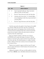
decoration, as shown in the X’mas project (Fig. 21.16), which has 15 flashing
LEDs and can play a tune.
This is the third time I’ve created a lighted Christmas tree with a PIC microcontroller.
In the first case, I hand-wired all the connections (which made it truly horrific to wire).
Figure 21.16 The Christmas tree decoration with
stickers for ornaments.
Simpo PDF Merge and Split Unregistered Version -
884 PROJECTS
The second version used a predesigned PCB card, but the design was lost in a hard file
crash (before I started religiously backing up files onto CD-ROM), and the software was
written for an early PIC microcontroller compiler that never worked extremely well. I
ended up updating it just for the light application (and the tune generator that went with
it). Also with the second version, I created an unnecessarily complex tune generator that
requires two separate PC applications to run before the code could be built with the tune
installed.
This third version avoids the problems of the other two, and by using LEDs with leads
soldered to them, the build time for the entire project is just a few hours (not includ-
ing decoration paint drying time). The application supports up to 16 LED outputs, a
speaker with software that can drive a 128-note tune, and a built-in power supply, so
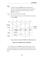
the application can be run from a wall-mounted ac/dc adapter. The schematic is shown
in Fig. 21.17. The bill of materials is listed in Table 21.7.
There are a couple of things to notice in this application. The first is that there is no
on/off switch for power. I left this off because I assumed that once power was applied,
the decoration would run continuously. Next, I do not interconnect the 74LS374s, which
are used as shift registers, because there are ample pins available for the application,
and randomizing can be done in software. Lastly, I used a 3.58-MHz ceramic resonator
instead of my typical 4.0-MHz one because I ran out of 4-MHz ceramic resonators. This
change did not result in a major problem with timing the application, as will be discussed
below. The macro calculator was used for calculating delays, and a 4-MHz ceramic res-
onator or crystal could be substituted in its place.
The software used to run the application could be considered to be a simple multitasker
with two “processes.” The critical process is the tune process, which plays a tune pro-
grammed into a tape. The other process is a pseudorandom number generator using as a linear
feedback shift register that runs in the foreground. The application can be modeled as
main ( ) // Xmas Tree high level code
{
int TuneDelay = 1;
int TuneIndex = 0;
int Data = 0x0FFFF;
PORTA = output; // Set Up Outputs
OPTION = TMRO Instruction Clock | TMRO Prescaler;
// Set Up Timer
INTCON = GIE | TOIE; // Enable Timer Interrupt
While (1 = = 1) { // Loop Forever Updating LEDs
dlay(); // Delay 1 second
Data = (data << 1) + (Data.15 ^ Data.12);
// Create Pseudo Random Number
Simpo PDF Merge and Split Unregistered Version -
885
Figure 21.17 Christmas decoration schematic.
Simpo PDF Merge and Split Unregistered Version -
886 PROJECTS
ShiftOut(Data); // and Shift it out to the LEDs
}
} // End Xmas Mainline
Interrupt TMROInt() // Timer0 Interrupt Handler
{
TMRO = Note(TuneIndex); // Reset TMR0 to Delay Again
TOIF = 0;
TuneDelay = TuneDelay – 1;
if (TuneDelay = = 0) { 1 // If Tune Delay Finished, Output a
TuneIndex = TuneIndex – 1;// New Note
if Note(TuneIndex) == 0) // At End of the Tune?
Tune index = 0; // Yes, Reset and Start Again
TABLE 21.7 XMAS BILL OF MATERIALS
REFERENCE DESIGNATOR DESCRIPTION
U1 PIC16F84–P/04
U2 7805
U3–U4 74LS374
Y1 3.58-MHz ceramic resonator with built-in capacitors
D1 1N4001 silicon diode
D2–D17 Multicolored LEDs with leads soldered on
C1 10-F, 16-V electrolytic
C2, C4–C6 0.1-F, 16=V tantalum
C3 0.47 F, any type
R1 10 k⍀,
1
/
4
W
R2–R19 220 ⍀,
1
/
4
W
S1 Single pole, single throw
S1 Piezo speaker
J1 2.5-mm power connector
Misc PCB board, wall-mounted 8-V, 500-mA ac/dc power
converter
Simpo PDF Merge and Split Unregistered Version -
MID-RANGE DEVICES 887
TuneDelay = Delay(TuneIndex);
} else // Toggle Note
if (Note(TuneIndex) != Pause)
SpkrOutput = SpkrOutput ^ 1;
} // End TMR0 int.
The table (listed as the “Note” and “Delay” functions in the code above) contains the
tune with notes and duration programmed in using the note add macro. This macro
will allow development of the code needed for a tune very quickly—just transcribe the
tune into the note range described below, and program a PIC microcontroller.
After getting a PCB built, you will be able to solder the application together in less
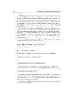
than an hour. The PCB design is shown in Figs. 21.18 through 21.20.
For my application, I created the Christmas tree shown in Fig. 21.16. The PCB has
two 0.125-in holes drilled in it for your use in mounting it to a display. When I
mounted my board to the Christmas tree, I simply screwed it to the back of the tree
using small wood screws. This is shown in Fig. 21.21. When I assembled this project,
T225A Overlay
Figure 21.18 Silkscreen for component
placement on the Christmas decoration.
Simpo PDF Merge and Split Unregistered Version -
888 PROJECTS
T225A Top Layer
Figure 21.19 The topside PCB
traces for the Christmas decoration.
T225A Bottom Layer
Figure 21.20 The bottom PCB traces
for the Christmas decoration.
Simpo PDF Merge and Split Unregistered Version -
MID-RANGE DEVICES 889
I tried to keep the LED wires away from the PCB to allow removal of the PIC micro-
controller for reprogramming, as well as allowing me to fix any potential problems
(there weren’t any).
For previous Christmas tree projects, I laboriously soldered leads onto LEDs and then
glued them into holes on the tree. For this project, I was able to find LEDs that were
presoldered onto leads and glued into panel-mount plastic carriers. These parts are a bit
more expensive than buying LEDs and wires, but the time saved made the project quite
enjoyable rather than a particularly odious chore.
For my Christmas tree, I used a piece of scrap pressboard cut into an equilateral
triangle 8 in on a side and a
3
/
4
-in piece of wood for the stand, as shown in Fig. 21.22.
I painted the triangle forest green and the base and stand gold. To assemble the tree,
I simply glued the triangle to the stand and screwed the stand to the base.
After the glue and paint had dried, I inserted the LEDs into the holes and soldered
their leads to the PCB. Total time working on the tree was about 2 hours, with a total
elapsed time of 3 days (mostly for paint and glue to dry).
When the tree was completed, it seemed to be a bit bare. To help dress it up, I bought
a few sheets of small sparkly stickers that had various toys and Christmas decorations
and gave them and the tree to my 4
1
/
2
-year-old daughter to decorate. This turned out to
be a lot of fun for her. As a bonus, if enamel paint is used with a smooth surface for the
tree triangle, the stickers can be peeled off easily and the tree redecorated the next year.
Creating tunes is a relatively simple chore. Once you have chosen the song you
would like the application to play, you will have to transpose it into the notes provided
in Table 21.8.
Figure 21.21 The rear of the Christmas decora-
tion showing the PCB and the wiring.
Simpo PDF Merge and Split Unregistered Version -
890 PROJECTS
TABLE 21.8 XMAS NOTE TABLE
NOTE LABEL FREQUENCY, HZ COMMENTS
B lnB 494 B below middle C
C nC 523 Middle C
C# nCS 554
D nD 587
D# nDS 622
E nE 659
F nF 699
F# nFS 740
G nG 784
G# nGS 831
A nA 880
A# nAS 923
B nB 988
C hnC 1047 Octave above middle C
C# hnCS 1109
D hnD 1175
D# hnDS 1245
E hnE 1319
Pause nP N/A Pause a sixteenth beat
Completed
Tree
Tree
Base
Stand
8" on Each Side 6" Wide
3" Deep
30 Deg.
3/4"
Thick
1/4"
Pressboard
3/4" Wide
3/4" Deep
6" High
Drill 15
1/4" Holes
Randomly in
“Tree”
Paint:
Tree - Leaf Green
Base & Stand - Gold
Figure 21.22 The wood pieces for the Christmas
decoration.
Simpo PDF Merge and Split Unregistered Version -
MID-RANGE DEVICES 891
When specifying the time for the note, the delay is given in 16 beats. To specify a
tune, the notes are specified along with the number of sixteenth beats. For example, the
first line of “Oh Christmas Tree,” which is
“Oh Christ-mas tree, Christ-mas tree, how lovely are . . .”
1/8D 3/16G 1/16G 1/8A 3/16B 1/16B 3/8B 1/8B 1/8A 1/4C . . .
is written out as
nD,2,nG,3,nG,1,nG,6,nA,2,nB,3,nB,1,nB,6,nB,2,nA,2,nB,2,hnC,4 . . .
The application is timed for 72 beats per minute, which allows me to do a pretty good
rendition of “O Christmas Tree.”
Other songs can be programmed in very easily; to do this, I recommend buying a cheap
beginners piano book with Christmas carols (or other songs) and transcribing the notes.
This may be surprising, but the most difficult aspect of this application for me was to
find and transcribe a version of “O Christmas Tree” that had notes that fell in the proper
range for the application.
For driving the LEDs seemingly randomly, the pseudorandom formula
Data = (data << 1) + (data.15 ^ data.12)
shifts the current value up by 1 bit and then fills in the least significant bit with the most
significant bit and another XORed together. This seems unbelievably simple (and it is),
but it does a very good job of randomizing the data as a very simple linear feedback
shift register.
The two 74LS374s are wired as synchronous serial shift registers. I use this format
for a variety of different applications to shift data serially out to a parallel I/O. To shift
the data out, notice that I perform a shift on the data with the carry up from the lower
byte being used as the LSB of the upper (the lower bytes LSB is the pseudorandom value
discussed earlier).
The xmax040.asm application code is in the code/Xmas folder. If you decide to
put in your own tune, then change the name of the file so that you don’t overwrite the
original application.
IRTank: TV IR REMOTE-CONTROL ROBOT
In this chapter I present two different robot features that can be controlled by a PIC. This
section will show you how to use the PIC microcontroller with a TV remote control to
send commands to a tracked vehicle. At the end of this chapter I’ll go through a pro-
grammable servo controller.
The genesis of this project was an article in Electronics Now. In the preceding proj-
ect I made the observation that hobbyist magazines always have Christmas decorations
in their November–December issues. On the other hand, you’ll notice a number of dif-
ferent robot designs throughout the year. The magazine project presented a simple
Simpo PDF Merge and Split Unregistered Version -
892 PROJECTS
differentially driven robot that could be controlled by a TV remote control. After look-
ing through the article, I decided to build my own robot (Fig. 21.23) because there were
a few things that I could improve on.
The project in the article used a single infrared (IR) receiver (typically used with TV
remote controls) to control the robot. Two motors (for the robot’s left and right sides)
were switched on and off by an H bridge motor control made out of discrete transis-
tors. The magazine robot used a PIC 16C5x for control. I felt that by using a mid-range
part, I would have the advantage of interrupts to handle the incoming commands (which
I’ll refer to as data packets).
Most (if not all) IR TV remotes use a space-width encoding scheme in which the data
bits are embedded in the packet by varying the lengths of certain data levels. This can
be seen in Fig. 21.24 from a theoretical perspective and from the practical (oscilloscope
output of a TV remote control IR receiver) in Fig. 21.25.
The normal signal coming from an IR receiver circuit is high when nothing is coming
(line idle) and then goes low with a leader signal to indicate that data is coming in.
The data consists of a bit Synch, whose value, when complete, is transmitted as the
Figure 21.23 The completed IR-controlled tank.
Figure 21.24 The output of a TV remote-control
receiver consists of a number of pulses that are sep-
arated by different-length spaces that are used to
encode data.
”
”
”
“ ”“
“
“
”
“
”
“
Simpo PDF Merge and Split Unregistered Version -
MID-RANGE DEVICES 893
length of time before the next bit Synch. The IR robot is designed for Sony TV remotes,
which have 12 data bits and a 40-kHz carrier. The timings are listed in Table 21.9 (and
use a base timing T of 550 s).
To read the incoming signal, I used the following state machine code in an interrupt
handler that differentiated between TMR0 overflows and PORTB change on interrupt:
interrupt IRTankInt() // Handle Incoming IR Serial Data
{
if (INTCON.T0IF != 0) {
// TMR0 Overflow – Timeout Indicating Invalid
// Data Being Received
1) Ch 1 5 Volt 25 us
Figure 21.25 An oscilloscope view of the TV IR remote-control receiver output.
TABLE 21.9 SONY IR REMOTE-CONTROL TIMING
FEATURE T TIMING ACTUAL LENGTH
Leader 4T 2.20 ms
Synch pulse T 0.55 ms
0T0.55 ms
12T1.10 ms
Simpo PDF Merge and Split Unregistered Version -
894 PROJECTS
BitCount = 0; // Prepare for the Next Packet
State = 0;
INTCON = 1 << RBIE; // Wait for Change on PORTB
Interrupt Request
// Also Reset “T0IF”
} else { // Else, Handle Incoming Bit Transition
Temp = PORTB; // Save the Changed State in PORTB to
Reset
// Interrupt Request
INTCON = (1 << RBIE) + (1 <<T0IE);
// Reset and Enable TMR0 and RB Interrupts
switch(State) { // Handle PORTB Change Based on Current
State
case 0: // Expect Leader/Synch Coming In
TMR0 = 5msec; // Leader Valid for 2.2 msec –
Put in Timeout
State = State + 1;
Value = 0; // Haven’t received anything yet
break;
case 1: // End of Leader/Get “Synch”
TMR0 = 1 msec; // “High” Synch Pulse is Valid
for 0.55 msec
BitCount = 12; // Expect twelve Incoming Bits
State = State + 1;
break;
case 2: // Start of Synch Bit - Come back here for
// Each One
TMR0 = 2 msec; // “Low” Value can be valid for 1.10 msec
State = State + 1;
break;
case 3: // Bit Ended - Use TMR0 to Get Value
Value = Value >> 1;
Simpo PDF Merge and Split Unregistered Version -
MID-RANGE DEVICES 895
If (TMR0 < 0.8 msec)
Value.msb = 1;
// If Less than 0.80 msec has passed, then
// “1” was received
BitCount = BitCount – 1;
if (BitCount == 0) {
DataFlag = 1 // Flag Mainline that Data is Available
INTCON = 1 << RBIE;
}
} // end Switch
} // end if
} // End IRTankInt
This code has the advantage of being able to discriminate between different manu-
facturers’ IR codes (the differences lay in the length of time during the transitions, the
number of bits, and the IR carrier frequency).
As I said earlier, one of the features I didn’t like about the magazine article robot was
its use of a single IR receiver. I was concerned that this would not provide adequate recep-
tion in a crowded room where the robot could be turned in different directions relative
to the remote control.
For my robot, I decided to use two IR receivers pointing 180 degrees apart (this can
be seen in the figure; the IR receivers are the two square metal cans at the front of the
robot). This gives almost 360-degree coverage.
By doing this, a new problem came up, and that was the problem of arbitration. I found
that one receiver may not pick up the transmitted signal or that it would be a 40-kHz
cycle or two ahead or behind the other receiver. The arbitration scheme used is quite
simple. The first receiver to transmit the leader to the PIC microcontroller is the one that
is “listened” to for the remainder of the data packet.
The application code can be found in the code\IRTank folder. The application
has been updated from the first edition’s code to use a PIC16F84 instead of a
PIC16C84. Irtank.asm was based on Test9A from the first edition. This was the
last application in the series of programs written to understand how TV remote con-
trols work and then build up the understanding into the final application. One thing
that I am proud of in this application code is that when I created it, I had nothing like
an oscilloscope to debug it. I was able to figure out the actual times by writing simple
applications that mapped out signal timing, and I was able to differentiate the codes
that were being sent. Once I had enough information to understand how the remote
control worked, I was able to write the application.
The IR receiver the code was developed using a LiteOn 40-kHz IR remote control
receiver module (Digi-Key Part Number LT1060-ND). This receiver was connected up
to a PIC microcontroller that had a number of LEDs on PORTB/PORTA to try to decode
what was happening. Since the original version of the robot was created, many different
Simpo PDF Merge and Split Unregistered Version -
896 PROJECTS
manufacturers of 32-, 36-, 38-, and 40-kHz IR remote-control receivers have come on
the scene from which you can choose.
Once I had the IR interface worked out, I thought I was away to the races.
Unfortunately, this did not turn out to be the case. As a robot platform, I bought two
Tamiya tracked vehicle parts kits (Item 70029). Each one has a single electric motor and
gearbox—buying two gave me a motor and gearbox for each side’s tracks. Running the
motors, I found that they used about 250 mA, which was within the stated current
ranges of the H drive used in the magazine robot’s circuit. I then went off happily build-
ing the magazine circuit’s H drive.
After hooking up the recommended circuit, nothing happened except the transistors
got very hot (one actually exploded). This lead to (literally) several weeks of asking ques-
tions and experimenting with different circuits (I even pulled out some of my old tran-
sistor textbooks—when I did that, I knew I was really desperate) until I determined that
I had a circuit that wouldn’t work for this application.
To make a long story short, I decided to see what others had done before me. Looking
up robotics web sites (such as the Seattle Robotics Society), I discovered the L293D chip,
which is a single integrated circuit that provides the H drive function for two motors
(making this application much easier to wire than the original circuit that used eight dis-
crete transistors and resistors). The L293D consists of four drivers (with clamping diodes)
and is designed to be used as a two-motor H drive control. The circuit in Fig. 21.26 shows
how one-half of the L293D can be used to control a motor.
Now, with everything working properly, I came up with the circuit shown in Fig. 21.27.
The controller to be used is a universal remote control set to Sony TV. For the electron-
ics, I used the parts listed in Table 21.10.
Four AA alkaline batteries provided power for my prototype. Using nickel-cadmium
batteries, I found the robot to be very sluggish. Trying to figure out the cause of the
1
2
3
4
5
6
7
8
10
11
12
13
14
15
16
V
cc
Motor
Power
MCU
PWM
Motor
Directn
Motor
Optional
“Snubber”
5 Ohm
0.1 uF
9
Figure 21.26 The L293D dual H-drive chip is an excel-
lent part to use when you are starting out in robotics and
want to have a reliable and efficient motor driver.
Simpo PDF Merge and Split Unregistered Version -
MID-RANGE DEVICES 897
sluggish performance, I found that the tracks and axles were binding because they
weren’t exactly square. The Tamiya tracked vehicle kit provides a piece of hardwood
to put the various pieces on. This is an extremely hard piece of wood and didn’t take
well to precision placement of parts. I ended up using the piece from the second kit and
had better results.
A much better solution for this project is to buy a Tamiya wall-hugging mouse kit
(Item 70068-1300), which contains two motors, two gearboxes, and a plastic chassis to
V
cc
Figure 21.27 The IR remote-controlled robot
schematic.
TABLE 21.10 IRTANK BILL OF MATERIALS
REFERENCE DESIGNATOR DESCRIPTION
U1 PIC16F84
U2 L293D motor driver
Y1 4-MHz ceramic resonator with built-in capacitors
R1 10 k⍀,
1
/
4
W
R2, R3 100 ⍀,
1
/
4
W
C1 0.1-F, 16-V tantalum
C2, C3 10-F, 35-V electrolytic
RST Momentary-on pushbutton switch
I/R Rx’ers 40-MHz IR remote-control receiver modules
Miscellaneous Prototyping PCB, 4 ϫ AA alkaline batteries,
4
ϫ AA battery clip, wiring
Robot base Tamiya tracked vehicle parts kit (Item 70029)
Simpo PDF Merge and Split Unregistered Version -
898 PROJECTS
keep everything aligned. I’ve used this kit for a number of robots over the years with
much better results (giving my kids something to terrorize our cats with).
IRBetter: ADDENDUM IR ROBOT
Sometime after I completed the IR remote-controlled robot (and the kids were well on
their way to demolishing it), a question came up on the PICList concerning alternative
methods of reading infrared remote control transmissions. The question was about sam-
pling and learning the received data packet rather than comparing each incoming bit to
a predetermined value. The question sparked the idea of representing the codes inside
the PIC microcontroller in other ways.
My first attempt at this was to count the number of ones during a sample period.
Knowing that a characteristic pattern of ones and zeros would be sampled, I felt that I
should be able to get a reasonably precise value for the transmitted packet. This was the
beginning of IRLCD_2 in the code/IRBetter folder. To test out the code, I created
a breadboard circuit using the schematic in Fig. 21.28.
Note that this circuit uses the serial LCD interface described earlier in this chapter. Using
the LCD really made debugging this experiment (I wouldn’t go so far as to call it a proj-
ect) a lot easier and is a good example of the usefulness of a simple UART interface.
The main body of the code, where the IR stream is read/sampled, is
movlw 0x0A0 ; Setup the Timer Interrupt
movwf INTCON
Loop: ; Loop Here for Each Update of Screen
movlw 200 ; Wait for the Time Out
subwf IntCount, w
btfss STATUS, Z
V
dd
V
cc
V
cc
Figure 21.28 Test circuit for better operation of the PIC
microcontroller IR receiver application code.
Simpo PDF Merge and Split Unregistered Version -
MID-RANGE DEVICES 899
goto Loop ; Has NOT timed out
movlw 200 ; Can we Display?
subwf ReadCount, w
btfsc STATUS, Z
goto Loop_Reset ; Reset the Count Values
movf ReadCount, w ; Now, Display what was read in
clrf IntCount ; Clear the Display Values
clrf ReadCount
call DispHex ; Display the Hex Value
movlw 0x08E ; Reset the Cursor for Writing
call WriteINS
goto Loop ; Wait for the Next Loop Around
Loop_Reset:
clrf IntCount ; Reset the Values
clrf ReadCount
goto Loop
Int: ; Interrupt, Check I/R Input
movwf _w ; Save the Context Registers
swapf STATUS, w
movwf _status
bcf INTCON, T0IF ; Clear the Timer Interrupt
incf IntCount ; Increment the Count Register
btfsc PORTB, 6 ; Increment the Read Value?
incf ReadCount
movlw 256 - 25 ; Reset the Timer
movwf TMR0
swapf _status, w ; Restore the Context Registers
movwf STATUS
swapf _w
swapf _w, w
retfie
Simpo PDF Merge and Split Unregistered Version -
900 PROJECTS
This code simply counts the number of ones and stores the result in ReadCount for
a given amount of time. The theory behind this method of sampling was that the dead
space between packets would be read along with the data, and the result would com-
bine them.
The actual value returned from the program wasn’t very repeatable (as was expected).
For example, five tries with the 1 key from a universal remote programmed with Sony
codes produced these results:
0x09F
0x09D
0x08C
0x09D
0x09D
Generally, the results from this program were repeatable about 60 percent of the
time. This might have been acceptable except for the poor discrimination that this
method had. For example, the codes for 2 and 3 are 0x081 and 0x082, respectively.
The problem lies in the fact that the two codes have the same number of ones and zeros.
The code may pick up the differences, but I didn’t find this to be the case.
Thus the code for reading the IR packet was changed to
clrf IntCount ; Reset the Counters
clrf ReadCount
GetPack: ; Get the Next Packet Coming In
movlw 0x088 ; Wait for Port Change Interrupt
movwf INTCON
Loop: ; Loop Here for Each Update of Screen
movlw 150 ; Wait for 25 msec of Data from I/R
subwf IntCount, w
btfss STATUS, Z
goto Loop ; Has NOT timed out
clrf INTCON ; No more interrupts for a while
movf ReadCount, w ; Get the Read in CRC
clrf IntCount ; Reset for the Next Packet
clrf ReadCount
call DispHex ; Now, Display the Character
movlw 0x08E ; Reset the Cursor
call WriteINS
Simpo PDF Merge and Split Unregistered Version -
MID-RANGE DEVICES 901
goto GetPack ; Wait for the Next I/R Packet
Int: ; Interrupt, Check I/R Input
movwf _w ; Save the Context Registers
swapf STATUS, w
movwf _status
movlw 0x020 ; Just wait for a Timer Interrupt
movwf INTCON
movlw 256 - 20 ; Reset the Timer
movwf TMR0
incf IntCount ; Increment the Count Register
bcf STATUS, C ; Now, Figure out what to Add to
LSB
btfsc PORTB, 6 ; Is the Incoming Value Set?
goto Int_Set
btfsc ReadCount, 5 ; Do we Update the Value coming in?
bsf STATUS, C
goto Int_End
Int_Set: ; Incoming Set
btfss ReadCount, 5 ; Is the Current Bit Set?
bsf STATUS, C ; No, Turn on the Incoming Bit
Int_End:
rlf ReadCount ; Shift Over with New Input Data
swapf _status, w ; Restore the Context Registers
movwf STATUS
swapf _w
swapf _w, w
retfie
which can be found as IRLCD_3.
The fundamental changes were that the sampling started after the leader was received,
and the 1s and 0s were treated as the inputs to a linear feedback shift register. Elsewhere in
this book I have discussed how linear feedback shift registers work. For the preceding code,
an 8-bit LFSR was used to produce cyclical redundancy check (CRC) codes. In this case,
the input isn’t the high bit of the shift register—instead, it is the input from the IR receiver.
Using this code, the CRC codes listed in Table 21.11 were generated from the Sony
IR transmitter.
Simpo PDF Merge and Split Unregistered Version -
902 PROJECTS
The interrupt handler code waits for a port change interrupt (the IR line going low
from its nominal state of 1), and once that happens, the line is sampled every 200 s,
and a CRC is generated from each sample. After 150 samples (30 ms), the CRC is output
serially in hex format (i.e., sending the high nybble followed by the low one).
The CRC generated is rock solid (none of the 60 percent repeatability I had with just
sampling bits). I don’t know if I’m going to go back and update my IR robot code (lack
of initiative more than anything else), but this is clearly a much more elegant and robust
method of handling IR codes.
I did a limited amount of checking for invalid code rejection by reprogramming my
universal remote with Panasonic and RCA codes. The CRCs generated were different
from the Sony ones shown earlier.
I was never pleased with the XORing used to create the CRC in the preceding code.
I felt that it was too confusing to understand. After some thought, I came up with the
idea that if I used the same bit number for the PORT input bit as the CRC tap, I could
simplify the CRC generator (from bcf STATUS, C to rlf ReadCount above) to
bcf STATUS, C
movf PORTB, w ; Get the Value Read in
xorwf ReadCount, w ; XOR it with the current
andlw 0x040 ; Clear all the bits but the two
TABLE 21.11 IMPROVED IR TANK Read
ALGORITHM RESULTS
KEY CRC CODE
Power 0x52
Volϩ 0x5E
Vol– 0xBB
Chϩ 0xDC
0 0x17
1 0x7A
2 0x8D
3 0x33
4 0x1F
5 0x4E
6 0x72
7 0xCC
8 0xB9
9 0x23
Simpo PDF Merge and Split Unregistered Version -
MID-RANGE DEVICES 903
btfss STATUS, Z ; we’re interested and if not = 0
bsf STATUS, C ; then make LSB of the CRC = 1
rlf ReadCount
This code only improves the original by two addresses, but it sure is a lot easier to
understand. This is IRLCD_4.asm in the IRBetter folder.
When I implemented this change, I cheated a bit and changed the CRC tap (and not
the line coming in, which would have meant that I would have to change the LCD
code). But it still ran very well, with unique CRCs generated for each of the keys of the
Sony-mimicking universal remote.
I guess the moral of this whole escapade is that tremendous improvements in your
code (in terms of size and effort requirements) can be made if you look at a problem
from a different angle. The code literally took less than 6 hours to develop and debug
(compared with over 2 weeks for the original IR receiver code of the robot). The code
takes up about a third of the space of the IR read algorithm used in the robot and uses
only two 8-bit variables compared with the seven of the robot’s code. This is a tremen-
dous improvement!
Discussing this philosophically, it can be seen that this experiment actually restruc-
tures the application (reading an IR transmitter) to best fit the PIC microcontroller. The
data read is now totally 8-bit, as opposed to the 12/16 bits that had to be handled in the
original application.
Thermo: ELECTRONIC THERMOMETER WITH SEVEN
SEGMENT LED DISPLAYS
One of the most popular PIC microcontroller projects I have ever created is this elec-
tronic thermometer. The basic model shown here has served me well for a number of
years (Fig. 21.29), and I have even replicated it in 123 PIC Microcontroller Experiments
for the Evil Genius to demonstrate how the application could be implemented using HT
Soft’s PICC Lite. The application itself uses the resistor/capacitor network discussed
elsewhere in this book for determining the resistance value of a thermistor. The tem-
perature output is displayed on three seven-segment LEDs. The circuit is driven by a
PIC16F84 using a 1-MHz crystal. There are a number of possible areas for inaccura-
cies in this circuit, so I have included the ability to set a calibration value, which is stored
in the PIC16F84’s data EEPROM, which is used to allow the temperature range to be
set accurately.
The thermistor that I used was bought from Radio Shack, and while the part is widely
available in North America, it cannot be ordered under the Radio Shack brand name else-
where in the world. I have described the operation of the thermistor so that you can find
the equivalent part numbers in your own location.
One comment/caveat for readers who want to use this project as a basis for other
applications: This is not a precision instrument. Despite inclusion of the capability of
calibrating the output temperature, you should not assume that this thermometer can be
used for precision operations. I am putting in this warning because I know of at least
two people who have used this circuit to control the temperature in their barns. While
Simpo PDF Merge and Split Unregistered Version -
904 PROJECTS
I have not heard any negative feedback regarding the circuit’s operation or accuracy,
I should point out that if you are looking for accurate temperature readings, use the
DS1820 digital thermometer, which has an interface application presented later in this
chapter. In terms of actual applications, this circuit apparently has been used as the basis
for a thermostat in a chicken-hatching incubator without any ill-effects to the chicks.
I suspect that this circuit is reasonably good around a small set range, although I would
be very wary of the accuracy of results returned over a wide temperature range.
The code displays the current temperature in degrees Celsius. The thermistor was
bought from Radio Shack (Part Number 271-110). This part is a 10-k thermistor with
a negative temperature coefficient (NTC) of –3.85 percent. This means that for each
degree Celsius the thermistor is raised, the resistance within the thermistor drops by
3.85 percent. The base temperature is 25ЊC, and the thermistor’s response to different
temperatures is listed in Table 21.12.
To create the thermometer, I created the circuit shown in Fig. 21.30. My prototype
was built on a phenolic prototyping board that was bought as part of a prototype box.
The bill of materials for this project is listed in Table 21.13.
The seven-segment LED displays used are of a common cathode type (which is to
say the cathodes of all the LEDs within the display are connected to common pins) that
takes up a 14-pin 0.300-in DIP pattern. The pinout of the conventional seven-segment
LED displays is shown in Fig. 21.31. When I first created this application, I couldn’t
find the standard reference to the display, so I came up with my own standard (which
is almost right). In Fig. 21.31 I have included a table to allow you to convert between
my number convention and the universal letter convention. DP is for the display’s dec-
imal point.
Figure 21.29 The completed digital thermometer.
Simpo PDF Merge and Split Unregistered Version -
MID-RANGE DEVICES 905
To drive the LEDs, I control the connection through the common cathode to ground
using a 2N7000 N-channel MOSFET. Each segment is toggled through one five-
hundredth of a second to display the three-digit temperature on the display.
In the schematic, I show (and for my prototype I used) a 9-V alkaline radio battery.
Instead of a 9-V battery, an ac/dc wall adapter can be used for the circuit. When you
TABLE 21.12 RESISTANCE VERSUS TEMPERATURE
FOR THE RADIO SHACK THERMISTOR
TEMPERATURE ACTUAL RESISTANCE
20ЊC12.079 k
21ЊC11.631 k
22ЊC11.200 k
23ЊC10.785 k
24ЊC10.385 k
25ЊC10.000 k
26ЊC9.615 k
27ЊC9.245 k
28ЊC8.889 k
29ЊC8.547 k
30ЊC8.218 k
U1
PIC16F84
U2
78L05
C1
10 uF
C2
0.1 uF
J1
9 Volt
V
dd
V
ss
Top
14
5
RA2
RA3
RA4
RA0
RB6
RB5
RB4
RB3
RB2
RB1
RB0
V
cc
1
2
3
6
7
8
9
10
11
12
17
++
OSC1
15
_MCLR
4
OSC2
16
Y1
4 MHz
C3/C4
30 pF
C5
0.1uF
R1
10 K
R10-100
R11
Thermistor
RB7
13
+
V
cc
LED1-LED3
14
1
13
2
6
7
8
9
4 12 4 12 4 12
Q1 - Q3
2N7000
V
cc
V
cc
RA1
18
SW2
R 13
10 K
R 12
10 K
SW1
SW1/SW2
Set Internal
Calibration
R2-R9
220
Top
Q1 Q2 Q3
Q3 shows
TO-92
Orientation
V
cc
V
cc
Figure 21.30 The digital thermometer schematic.
Simpo PDF Merge and Split Unregistered Version -
906 PROJECTS
TABLE 21.13 DIGITAL THERMOMETER BILL OF MATERIALS
REFERENCE DESIGNATOR DESCRIPTION
U1 PIC16F84–04/P
U2 78L05
Y1 1.00-MHz crystal
C1 10-F electrolytic
C2, C5 0.1-F tantalum
C3, C4 30 pF
R1, R12, R13 10 k ⍀,
1
/
4
Wt
R2–R9 220 ⍀,
1
/
4
W
R10 100 ⍀,
1
/
4
W
R11 10 k⍀, –3.85% NTC thermistor
(Radio Shack Part Number 271-110)
Q1–Q3 2N7000 N-channel MOSFET in TO-92
package
LED1–LED3 7-segment common cathode LED
displays
J1 9-V battery connector
SW1, SW2 2 ϫ 1 0.100-in pin headers
Misc. Prototyp
e PCB, experimenter’s box,
wire
DP
1
6
23
4
5
7
Cathode
DP
1
2
3
4
5
6
7
Cathode
Note: The following
Table Converts Segment
Numbers to
Conventional Letters:
Number Letter
1 B
2 C
3 D
4 E
5 F
6 A
7 G
Figure 21.31 Pinout for a seven-segment common-
cathode LED.
Simpo PDF Merge and Split Unregistered Version -
MID-RANGE DEVICES 907
look at my circuit, notice that I included an SPST switch for turning on and off power
to the circuit.
Each LED segment is connected to a PIC pin via a 220-⍀ resistor, except for the seg-
ment connected to RA4, in which the 220-⍀ resistor is attached to Vdd, and the PIC
pin pulls it low to turn off the LED. This is to avoid the issue of RA4 not being able to
drive positive signals and ensures that there is no possibility for high currents to be sunk
by RA4. This was done to avoid both the PIC microcontroller being burned out and to
minimize current consumption when RA4 is pulling the line low.
In my application, I wired the segments as
RA2 is connected to segment 6.
RA3 is connected to segment 5.
RA4 is connected to segment 1. Note the comments above.
RB0 is connected to segment 7.
RB1 is connected to segment 4.
RB2 is connected to segment 3.
RB3 is connected to segment 2.
The decimal point (DP) pin of the LED display was left unconnected.
The reason for using these values was strictly to make the wiring easier. If you look
at Figure 21.29, you’ll see that the seven current-limiting resistors are placed between
the PIC and the LED displays. The seven-segment LED display connections use the seven
I/O pins on the left side of the PIC microcontroller.
When creating an application such as this, you really have to plan ahead. In this
application, the best example of this is wiring the seven left-side PIC microcontroller
I/O pins directly to the current-limiting resistors and then to the seven-segment LED
displays to avoid having to come up with very complex wiring. To help simplify the
wiring even further, I also put the switching transistors along the bottom of the seven-
segment LED displays to allow a common ground to be run to each one. Even with this
planning, I still had to move around a couple of components and wire them on the
backside of the board to get everything to work together. The final mess of wires is shown
in Fig. 21.32.
A useful strategy to use in the application development process is to make sure that each
subsystem in the application is tested before the final application is created. The source code
for the Thermo application (thermo.asm) can be found in the code\Thermo folder.
The program uses the following formula
Time ϭ R ϫ C ϫϪln(V
end
/V
start
)
to measure the resistance of the thermistor. To initially calculate the actual temperature,
I used idealized components and had the temperature looked up from a table (because
the thermistor resistance versus temperature is a nonlinear function, and I didn’t want
Simpo PDF Merge and Split Unregistered Version -