beginning opengl game programming 2004 phần 8 pptx
Bạn đang xem bản rút gọn của tài liệu. Xem và tải ngay bản đầy đủ của tài liệu tại đây (617.36 KB, 25 trang )
Now that you understand the reasons for using vertex arrays, it’s time to learn how they
are used.
Array-Based Data
So far, we’ve been using relatively simple objects in our demos, and thus, we’ve been able
to describe them explicitly in the code. In a real game, however, you’ll be working with
models containing hundreds or even thousands of polygons, and describing such compli-
cated models directly in the code just isn’t practical—even if you manage to create
decent-looking results, it’s going to be a nightmare to maintain. Instead, one of the fol-
lowing two approaches is usually taken:
■
Load the model from a file. Dozens of great modeling packages enable you to cre-
ate a model visually and then export the geometric data to a file, which can be read
by your program. This approach offers the greatest flexibility. Model loading will
be discussed in much greater detail later in the book.
■
Generate the model procedurally. Some things you want to represent can be
implicitly described with equations due to patterns they contain or because they
possess some random properties that you can generate on the fly. A good example
of this is fractals. Geometric data for fractals can be created by a procedure that
produces the same values every frame.
Whichever approach is used, it should be fairly obvious that you don’t want to repeat all
the work every frame—you certainly don’t want to be constantly reading a model from
disk, and even procedural methods can have enough overhead to have an adverse effect
on performance. Instead, you’ll take the geometric data these methods generate and store
it in arrays, which you can then access as needed.
This process can be summarized in the following steps:
1. Generate the data you need, either procedurally or from a model file on disk.
2. Save this data in an array or set of arrays (for example, you could put the position
of each vertex in one array, the vertex normal in another, color in another, and so
on).
With your data stored in arrays, it’s ready for use by OpenGL’s vertex array functions.
Enabling Vertex Arrays
Like most OpenGL features, to be able to use vertex arrays, you must first enable them.
You might expect this to be done with
glEnable()
, but it’s not. OpenGL provides a sepa-
rate pair of functions to control vertex array support:
void glEnableClientState(GLenum array);
void glDisableClientState(GLenum array);
Chapter 10
■
Up Your Performance228
10 BOGL_GP CH10 3/1/04 10:05 AM Page 228
TLFeBOOK
The
array
parameter is a flag indicating which type of array you’re enabling (or disabling).
Each type of vertex attribute you want to use (for example, position, normal, color) can
be stored in an array, and you need to enable whichever attributes you are using individ-
ually, using one of the flags listed in Table 10.2.
TIP
It is common in OpenGL documentation to refer to all these array types collectively as
vertex arrays
,
which can be confusing because there is also a specific array type that is called a vertex array. That
said, they are collectively referred to as vertex arrays because each array contains data that is ref-
erenced on a per-vertex basis. The array type containing positional information is specifically called
a vertex array because the data stored in it is used internally as if calls to
glVertex()
were being
made. If you’ll notice, the name of each array type roughly corresponds to the name of the OpenGL
call that will be made on the data it contains (color arrays mimic
glColor()
, texture coordinate
arrays mimic
glTexCoord()
, and so on).
Working with Arrays
After you have enabled the array types that you will be using, the next step is to give
OpenGL some data to work with. It’s up to you to create arrays and fill them with the data
you will be using (procedurally, from files, or by any other means, as we’ve already dis-
cussed). Then you need to tell OpenGL about these arrays so it can use them. The func-
tion used to do this depends on the type of array you’re using. Let’s look at each function
in detail.
Vertex Arrays 229
Table 10.2 Array Type Flags
Flag Meaning
GL_VERTEX_ARRAY
Enables an array containing the position of each vertex.
GL_NORMAL_ARRAY
Enables an array containing the vertex normal for each vertex
GL_COLOR_ARRAY
Enables an array containing color information for each vertex
GL_SECONDARY_COLOR_ARRAY
Enables an array containing color information for each vertex
GL_INDEX_ARRAY
Enables an array containing indices to a color palette for each vertex
GL_FOG_COORD_ARRAY
** Enables an array containing the fog coordinate for each vertex
GL_TEXTURE_COORD_ARRAY
Enables an array containing the texture coordinate for each vertex
GL_EDGE_FLAG_ARRAY
Enables an array containing an edge flag for each vertex
*Available only via the
EXT_secondary_color
extension under Windows.
**Available only via the
EXT_fog_coord
extension under Windows.
10 BOGL_GP CH10 3/1/04 10:05 AM Page 229
TLFeBOOK
In each of the following functions,
stride
indicates the byte offset between array elements.
If the data is tightly packed (meaning there is no padding between each element), you can
set this to zero. Otherwise you can use the stride to compensate for padding or even to
pack data for multiple attributes into a single array.
pointer
is a pointer to an array con-
taining the vertex data or, more specifically, points to the first element you want to use
within that array. The data type of the array is indicated by
type
. The other parameters will
be explained with each individual function.
void glVertexPointer(GLint size, GLenum type, GLsizei stride, GLvoid *pointer);
This array contains positional data for the vertices.
size
is the number of coordinates per
vertex, and it must be 2, 3, or 4.
type
can be
GL_SHORT
,
GL_INT
,
GL_FLOAT
,or
GL_DOUBLE
.
void glTexCoordPointer(GLint size, GLenum type, GLsizei stride, GLvoid *pointer);
This array contains texture coordinates for each vertex.
size
is the number of coordinates
per vertex, and it must be 1, 2, 3, or 4.
type
can be set to
GL_SHORT
,
GL_INT
,
GL_FLOAT
,or
GL_DOUBLE
.
void glNormalPointer(GLenum type, GLsizei stride, GLvoid *pointer);
This array contains normal vectors for each vertex. Normals are always stored with exactly
three coordinates (x, y, z) so there is no
size
parameter.
type
can be
GL_BYTE
,
GL_SHORT
,
GL_INT
,
GL_FLOAT
,or
GL_DOUBLE
.
void glColorPointer(GLint size, GLenum type, GLsizei stride, GLvoid *pointer);
This specifies the primary color array.
size
is the number of components per color, which
should be either 3 or 4 (for RGB or RGBA).
type
can be
GL_BYTE
,
GL_UNSIGNED_BYTE
,
GL_SHORT
,
GL_UNSIGNED_SHORT
,
GL_INT
,
GL_UNSIGNED_INT
,
GL_FLOAT
,or
GL_DOUBLE
.
void glSecondaryColorPointer(GLint size, GLenum type, GLsizei stride, GLvoid *pointer);
This specifies the secondary color array.
size
is the number of components per color,
which is always 3 (for RGB). The types allowed are identical to those for
glColorPointer()
.
Extension
Extension name:
EXT_secondary_color
Name string:
GL_EXT_secondary_color
Promoted to core: OpenGL 1.4
Function names:
glSecondaryColorPointerEXT()
Tokens:
GL_SECONDARY_COLOR_ARRAY_EXT
Chapter 10
■
Up Your Performance230
10 BOGL_GP CH10 3/1/04 10:05 AM Page 230
TLFeBOOK
void glIndexPointer(GLenum type, GLsizei stride, GLvoid *pointer);
This array represents color indices for use with palletized display modes.
type
can be set
to
GL_SHORT
,
GL_INT
,
GL_FLOAT
,or
GL_DOUBLE
.
Extension
Extension name:
EXT_fog_coord
Name string:
GL_EXT_fog_coord
Promoted to core: OpenGL 1.4
Function names:
glFogCoordPointerEXT()
Tokens:
GL_FOG_COORD_ARRAY_EXT
void glFogCoordPointer(GLenum type, GLsizei stride, GLvoid *pointer);
This array is used to specify fog coordinates.
type
can be set to
GL_FLOAT
or
GL_DOUBLE
.
void glEdgeFlagPointer(GLsizei stride, GLboolean *pointer);
Edge flags become important when displaying polygons as lines, and this array allows you
to specify which lines are edges. Unlike the other functions,
pointer
always points to an
array of Boolean values, so there is no
size
or
type
parameter.
NOTE
For each vertex attribute, you can have only a single array specified at any one time. This means
that if you want to represent more than one object in your game with vertex arrays, you have to
either combine all the data for them into a single set of arrays or have each object have its own set
of arrays that you switch between using
gl*Pointer()
. Although the former may be slightly faster
because it doesn’t require a lot of state changes, the latter is going to be easier to manage. In fact,
a typical rendering loop will change the current arrays for every object, calling several
gl*Pointer()
functions and enabling or disabling vertex attributes as necessary.
After you’ve specified which arrays OpenGL should use for each vertex attribute, you can
begin to have it access that data for rendering. There are several functions that you can
choose from.
glDrawArrays()
When this function is called, OpenGL iterates over each of the currently enabled arrays,
rendering primitives as it goes. To understand how it works, you need to look at the
prototype:
void glDrawArrays(GLenum mode, GLint first, GLsizei count);
Vertex Arrays 231
10 BOGL_GP CH10 3/1/04 10:05 AM Page 231
TLFeBOOK
mode
serves the same basic function as the parameter passed to
glBegin()
: It specifies which
type of primitive the vertex data should be used to create. Valid values are
GL_POINTS
,
GL_LINE_STRIP
,
GL_LINE_LOOP
,
GL_LINES
,
GL_TRIANGLE_STRIP
,
GL_TRIANGLE_FAN
,
GL_TRIANGLES
,
GL_QUAD_STRIP
,
GL_QUADS
, and
GL_POLYGON
.
first
specifies the index at which the iteration
should start, and
count
specifies the number of indices to process. It should be noted that
after a call to
glDrawArrays()
, states related to the array types being used are undefined. For
example, if using normal arrays, the current normal will be undefined after
glDrawArrays()
returns.
glMultiDrawArrays()
Extension
Extension name:
EXT_multi_draw_arrays
Name string:
GL_EXT_multi_draw_arrays
Promoted to core: OpenGL 1.4
Function names:
glMultiDrawArraysEXT()
,
glMultiDrawElementsEXT()
OpenGL provides the ability to draw multiple arrays with a single call via
glMultiDraw-
Arrays()
, which has the following prototype:
void glMultiDrawArrays(GLenum mode, GLint *first, GLsizei *count, GLsizei primcount);
This is similar to
glDrawArrays()
, except that the
first
and
count
parameters are now arrays,
and there is an additional parameter
primcount
that indicates how many elements are in
each array. Calling
glMultiDrawArrays()
is functionally equivalent to the following:
for (int i = 0; i < primcount; ++i)
{
if (count[i] > 0)
glDrawArrays(mode, first[i], count[i]);
}
At present, most OpenGL drivers implement this function exactly like the code above, so
it serves more as a convenience than a performance improvement.
glDrawElements()
This function is very similar to
glDrawArrays()
, but it is even more powerful. With
glDrawArrays()
, your only option is to iterate sequentially over the list, which means that
you can’t reference the same element more than once;
glDrawElements()
, on the other hand,
allows you to specify the array elements in any order, and access each of them as many
times as necessary. Let’s look at the prototype:
Chapter 10
■
Up Your Performance232
10 BOGL_GP CH10 3/1/04 10:05 AM Page 232
TLFeBOOK
void glDrawElements(GLenum mode, GLsizei count, GLenum type, const GLvoid *indices);
mode
and
count
are used just as in
glDrawArrays()
.
type
is the data type of the values in
indices
, and it should be
GL_UNSIGNED_BYTE
,
GL_UNSIGNED_SHORT
,or
GL_UNSIGNED_INT
.
indices
is
an array containing indexes for the vertices you want to render.
To understand the value of this method, it must be reiterated that not only can you spec-
ify the indices in any order, you can also specify the same vertex repeatedly in the series.
In games, most vertices will be shared by more than one polygon; by storing the vertex
once and accessing it repeatedly by its index, you can save a substantial amount of mem-
ory. In addition, good OpenGL implementations will perform operations on the vertex
only once and keep the results in a cache, so that all references after the first are virtually
free—as long as the vertex is still in the cache. The performance advantages of this should
be obvious.
glMultiDrawElements()
This function is to
glDrawElements()
what
glMultiDrawArrays()
is to
glDrawArrays()
. It has the
following prototype:
void glMultiDrawElements(GLenum mode, GLsizei *count, GLenum type, GLvoid **indices,
GLsizei primcount);
Again, the differences here are that
count
and
indices
are lists of
primcount
elements. Call-
ing this function is equivalent to the following:
for (int i = 0; i < primcount; ++i)
{
if (count[i] > 0)
glDrawElements(mode, count[i], type, indices[i]);
}
This can be useful for things like drawing multiple triangle strips from a single set of ver-
tex arrays. As with
glMultiDrawArrays()
, this function is more for convenience than any-
thing else.
glDrawRangeElements()
Extension
Extension name:
EXT_draw_range_elements
Name string:
GL_EXT_draw_range_elements
Promoted to core: OpenGL 1.2
Function names:
glDrawRangeElementsARB()
Vertex Arrays 233
10 BOGL_GP CH10 3/1/04 10:05 AM Page 233
TLFeBOOK
This function is similar in use to
glDrawElements()
. The primary difference is that the val-
ues in the vertex array that you are accessing fall within a limited range. For example, if you
have a vertex array containing 1,000 vertices, but you know that the object you’re about to
draw accesses only the first 100 vertices, you can use
glDrawRangeElements()
to tell OpenGL
that you’re not using the whole array at the moment. This may allow the OpenGL to more
efficiently transfer and cache your vertex data. The prototype is as follows:
void glDrawRangeElements(GLenum mode, GLuint start, GLuint end, GLsizei count,
GLenum type, const GLvoid *indices);
mode
,
count
,
type
, and
indices
have the same purpose as the corresponding parameters.
start
and
end
correspond to the lower and upper bounds of the vertex indices contained
in
indices
.
glArrayElement()
This is perhaps the least-efficient method of accessing vertex array data. Rather than call-
ing upon a range of data, it allows you to evaluate and render a single vertex, as follows:
void glArrayElement(GLint index);
index
is, naturally, the vertex you want to render. Using
glArrayElement()
is only marginally
more efficient than using immediate mode. For optimal efficiency when using vertex
arrays, you should favor
glDrawElements()
or
glDrawRangeElements()
.
Tip
OpenGL 1.5 added an even more efficient method for processing vertex data in the form of
vertex
buffer objects
, the primary advantage being that they allow you to create and store data in mem-
ory on your video card rather than in your PC’s main memory. We won’t be covering vertex buffer
objects in this volume, but we will in a future volume.
Quick Review
To be sure you understand how vertex arrays work, let’s recap. First, you need the data
with which you will fill the arrays, which can be loaded from a file, generated procedu-
rally, or defined by some other method. This data consists of a set of vertices describing
some object in your world. Each vertex can include information about its position, color,
texture coordinates, fog coordinates, edge flags, and/or normal vectors. In addition to
storing this data in one or more arrays, you need to enable vertex arrays for each data type
you will be using. Then you tell OpenGL to use each array with corresponding calls to
gl*Pointer()
.
Chapter 10
■
Up Your Performance234
10 BOGL_GP CH10 3/1/04 10:05 AM Page 234
TLFeBOOK
When you want to evaluate and render the data stored in these arrays, you make a call to
one of the functions listed above. For each vertex, OpenGL takes the data associated with
each attribute type and, in essence, applies the appropriate OpenGL call to that data. For
example, the color array data is used as if you had called
glColor()
, the normal data is used
as if you had called
glNormal()
, and so on. Note that these functions are not actually called
(after all, you could do that yourself and avoid the whole concept of vertex arrays
entirely), but the results are the same.
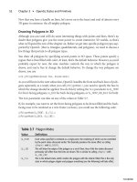
Interleaved Arrays
With the methods we’ve discussed so far, your vertex arrays will
look something like Figure 10.2, with each vertex attribute stored in
a separate array. Each of these arrays is passed independently via
one of the
gl*Pointer()
functions, and when a draw command is
made, OpenGL assembles data from each array to form complete
vertices.
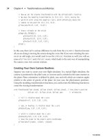
Instead of storing data for each attribute in separate arrays, you may
want to pack all of the data into a single array, as shown in Figure
10.3.
Vertex Arrays 235
Figure 10.2 Arrays for position, color, and texture coordinate attributes.
Figure 10.3 Position, color,
and texture coordinate data
stored in a single array.
10 BOGL_GP CH10 3/1/04 10:05 AM Page 235
TLFeBOOK
To be able to use this type of array, you could use the methods we’ve been discussing so
far by making use of the
stride
parameter. If the data from Figure 10.3 was in an array
called
vertexData
, you could use the following code to set it up:
glVertexPointer(3, GL_FLOAT, 8 * sizeof(GLfloat), vertexData);
glColorPointer(3, GL_FLOAT, 8 * sizeof(GLfloat), &vertexData[3]);
glTexCoordPointer(2, GL_FLOAT, 8 * sizeof(GLfloat), &vertexData[6]);
You could then use
glDrawElements()
or any other draw functions just as you normally would.
OpenGL provides an alternative approach in the form of
glInterleavedArrays()
:
void glInterleavedArrays(GLenum format, GLsizei stride, const GLvoid *pointer);
format
is used to indicate exactly what data appears in the array pointed to by
pointer
.It
can take on any of the values in Table 10.3.
stride
serves the same purpose as it does with
the various
gl*Pointer()
functions. Note that the data should be ordered in a manner con-
sistent with the ordering in the
format
parameter; i.e., texture coordinates are always first,
followed by colors, then normals, then positions.
Chapter 10
■
Up Your Performance236
Table 10.3 Interleaved Array Formats
Plane Description
GL_V2F
Position only, 2 elements (x,y)
GL_V3F
Position only, 3 elements (x,y,z)
GL_C4UB_V2F
* Color, 4 elements (r,g,b,a), and position, 2 elements (x,y)
GL_C4UB_V3F
* Color, 4 elements (r,g,b,a), and position, 3 elements (x,y,z)
GL_C3F_V3F
Color, 3 elements (r,g,b), and position, 3 elements (x,y,z)
GL_N3F_V3F
Normals, 3 elements, and position, 3 elements (x,y,z)
GL_C4F_N3F_V3F
Color, 4 elements (r,g,b,a), normals, 3 elements, and position, 3 elements (x,y,z)
GL_T2F_V3F
Texture coordinates, 2 elements (s,t), and position, 3 elements (x,y,z)
GL_T4F_V4F
Texture coordinates, 4 elements (s,t,r,q), and position, 4 elements (x,y,z,w)
GL_T2F_C4UB_V3F
* Texture coordinates, 2 elements (s,t), color, 4 elements (r,g,b,a), and position,
3 elements (x,y,z)
GL_T2F_C3F_V3F
Texture coordinates, 2 elements (s,t), color, 3 elements (r,g,b) and position,
3 elements (x,y,z)
GL_T2F_N3F_V3F
Texture coordinates, 2 elements (s,t), normals, 3 elements, and position,
3 elements (x,y,z)
GL_T2F_C4F_N3F_V3F
Texture coordinates, 2 elements (s,t), color, 4 elements (r,g,b,a), normals,
3 elements, and position, 3 elements (x,y,z)
GL_T4F_C4F_N3F_V4F
Texture coordinates, 4 elements (s,t,r,q), color, 4 elements (r,g,b,a), normals,
3 elements, and position, 4 elements (x,y,z,w)
* The C4UB type indicates colors represented as four floating point values stored in a single integer that is then cast to a
float. This is necessary because other data types are floats, and it’s not possible to have an array of multiple data types.
10 BOGL_GP CH10 3/1/04 10:05 AM Page 236
TLFeBOOK
Using interleaved arrays, the code above could be rewritten as:
glInterleavedArrays(GL_T2F_C3F_V3F, 0, vertexData);
In addition to setting a pointer to the vertex attribute data, a call to
glInterleavedArrays()
will also enable any arrays indicated in the
format
parameter and disable those that aren’t
being used.
Unfortunately, interleaved arrays have some serious limitations. They don’t support fog
coordinates, secondary color, or edge flags. They also only work with the currently active
texture unit, so multitexturing isn’t possible. However, if you have data that consists only
of position, color, normal, and/or texture coordinate information, interleaved arrays may
be more convenient than the standard method.
Vertex Arrays and Multitexturing
Extension
Extension name:
ARB_multitexture
Name string:
GL_ARB_multitexture
Promoted to core: OpenGL 1.2.1
Function names:
glClientActiveTextureARB()
Tokens:
GL_MAX_TEXTURE_UNITS_ARB
Using multitexturing (see Chapter 9, “More on Texture Mapping”) with vertex arrays
requires some additional setup beyond what we have discussed so far. Each texture unit
has its own set of states, and thus, vertex arrays can be enabled and disabled for each tex-
ture unit individually, and each has its own texture coordinate array pointer.
In OpenGL implementations supporting multitexturing, the texture unit that is active by
default is the first one. Calls to
glTexCoordPointer()
and
glEnableClientState()
/
glDisable-
ClientState()
with
GL_TEXTURE_COORD_ARRAY
affect only the currently active texture unit, so to
use vertex arrays with other texture units, you have to switch to them by activating them.
This is done with the following function:
void glClientActiveTexture(enum texture);
texture
is a constant corresponding to the unit that you wish to make active, and it must
be of the form
GL_TEXTUREi
, where
i
ranges from 0 to
GL_MAX_TEXTURE_UNITS
–1.
Vertex Arrays 237
10 BOGL_GP CH10 3/1/04 10:05 AM Page 237
TLFeBOOK
Caution
The state associated with
glClientActiveTexture()
is separate from the state associated with
glActiveTexture()
. When using multitexturing with vertex arrays, be sure to use the former, not
the latter.
After you have activated the texture unit you wish to modify, you can then make calls to
glTexCoordPointer()
to assign an array of values or
glEnableClientState()
/
glDisable-
ClientState()
to turn vertex arrays on or off for the current texture unit. Texture coordi-
nate arrays for all texture units are disabled by default. To set up vertex arrays for the first
two texture units, you’d use something like the following:
// Enable texture coordinate vertex arrays for texture unit 0
glClientActiveTexture(GL_TEXTURE0);
glEnableClientState(GL_TEXTURE_COORD_ARRAY);
// Specify an array (defined previously) to use with texture unit 0
glTexCoordPointer(2, GL_FLOAT, 0, (GLvoid *)texUnit0Vertices);
// Select and enable texture unit 1
glClientActiveTextureARB(GL_TEXTURE1);
glEnableClientState(GL_TEXTURE_COORD_ARRAY);
// Specify an array (defined previously) to use with texture unit 1
glTexCoordPointer(2, GL_FLOAT, 0, (GLvoid *)texUnit1Vertices);
After you’ve enabled and specified vertex arrays for each of the texture units you want
to use, there is nothing else you need to do. Subsequent calls to
glDrawArrays()
,
glDrawElements()
, and so on will use them just like any other vertex arrays.
Locking Arrays
Many OpenGL implementations provide an extension that enables you to lock and
unlock arrays. Locking the arrays lets the system know that, until they are unlocked, you
won’t be modifying the data in the arrays. Because OpenGL knows that the vertex array
data is not changing, it may be able to cache the transformations or place the arrays in
memory that can be accessed more quickly. This can lead to performance gains, especially
if you’re drawing the same geometry more than once. Because the vertex data is, in effect,
compiled, the name of this extension is
EXT_compiled_vertex_array
. The functions associ-
ated with this extension are
void glLockArraysEXT(GLint first, GLsizei count);
void glUnlockArraysEXT();
Chapter 10
■
Up Your Performance238
10 BOGL_GP CH10 3/1/04 10:05 AM Page 238
TLFeBOOK
The
first
parameter is the index of the first vertex you want to lock, and
count
is the total
number of vertices to lock, starting at the
first
index.
Extension
Extension name:
EXT_compiled_vertex_array
Name string:
GL_EXT_compiled_vertex_array
Promoted to core: No
Function names:
glLockArraysEXT()
,
glUnlockArraysEXT()
See the demo in the following section for sample code checking for and using this
extension.
Marbles
We’ve provided a demo in the Marbles directory in the folder for this chapter on the CD.
This demo draws a large number of marbles bouncing around inside a glass case with a
mirrored floor. Each marble shares the same data but is colored and positioned indepen-
dently. Immediate mode is used by default, but you can use the following keys to enable
some of the features covered so far in this chapter:
<SPACE> Toggles vertex arrays for the marbles using glDrawElements().
<TAB> Toggles display lists for everything.
<C> Toggles compiled vertex arrays.
You should definitely see an improvement in frame rate when enabling vertex arrays. Dis-
play lists and compiled vertex arrays may or may not improve performance, depending on
your hardware.
You’ll notice that when display lists are enabled, the marbles freeze in place. This is due to
the fact that each marble is positioned independently inside of the display list. Once the
display list is compiled, the data within it can’t be changed, so the marbles can’t move rel-
ative to each other. You could, however, move the marbles as a group.
You’ll also notice that when enabling compiled vertex arrays, the marble colors may
change to a single color. This is because all of the marbles share the same base set of data.
When the vertices get locked and cached away, the changes in the material may not get
picked up.
Vertex Arrays 239
10 BOGL_GP CH10 3/1/04 10:05 AM Page 239
TLFeBOOK
Let’s look at the most relevant code for the demo. First, after generating the data for the
marbles, the vertex arrays are set up as follows:
bool CGfxOpenGL::Init()
{
InitializeMarbles();
glVertexPointer(3, GL_FLOAT, 0, m_positions);
glNormalPointer(GL_FLOAT, 0, m_texCoords);
glTexCoordPointer(3, GL_FLOAT, 0, m_texCoords);
}
The texture coordinate data is being used for both texture coordinates and normals
because with cube-mapped spheres, the values are identical.
The relevant code for display lists happens in
Render()
, as shown below:
void CGfxOpenGL::Render()
{
if (m_useList)
{
// use the existing list if there is one
if (m_list)
{
glCallList(m_list);
return;
}
else // otherwise, create a new one
{
m_list = glGenLists(1);
glNewList(m_list, GL_COMPILE_AND_EXECUTE);
}
}
glLightfv(GL_LIGHT0, GL_POSITION, LIGHT_POSITION);
DrawFloor();
DrawReflection();
DrawMarbles(GL_FALSE);
DrawBox();
if (m_useList)
Chapter 10
■
Up Your Performance240
10 BOGL_GP CH10 3/1/04 10:05 AM Page 240
TLFeBOOK
glEndList();
}
Finally, the vertex arrays are put to use inside of
DrawMarbles()
:
void CGfxOpenGL::DrawSphere()
{
if (m_useVertexArrays)
{
for (int i = 0; i < m_numStrips; ++i)
{
glDrawElements(GL_TRIANGLE_STRIP, m_vertsPerStrip, GL_UNSIGNED_INT,
&m_indexArray[i * m_vertsPerStrip]);
}
}
else // draw using immediate mode instead
{
for (int i = 0; i < m_numStrips; ++i)
{
glBegin(GL_TRIANGLE_STRIP);
for (int j = 0; j < m_vertsPerStrip; ++j)
{
int index = m_indexArray[i * m_vertsPerStrip + j];
glNormal3fv(m_texCoords[index].v);
glTexCoord3fv(m_texCoords[index].v);
glVertex3fv(m_positions[index].v);
}
glEnd();
}
}
}
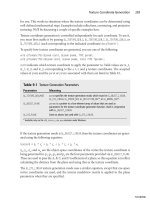
A screenshot of the Marbles demo can be seen in Figure 10.4. Be sure to check out the
source code on the CD to ensure that you fully understand how vertex arrays work.
Frustum Culling
One of the most basic rules in developing an efficient graphics engine is this: Don’t draw
what you can’t see. For this reason, many algorithms have been developed to allow you to
quickly identify large sets of data that can’t possibly be seen by the viewer so that they can
be discarded instead of sending them to the graphics hardware. We don’t have space to
even scratch the surface of the various methods available, but we will show you how to do
something they almost all rely on: view-frustum culling.
Frustum Culling 241
10 BOGL_GP CH10 3/1/04 10:05 AM Page 241
TLFeBOOK
As you’ll recall, the view frustum defines the region of the world space that you can see.
Usually, it is defined in terms of a camera, including the location of the viewer, field of
view, and so on. In reality, this information is used to construct six planes that bound the
view frustum. Anything within this frustum is visible (unless something else inside of the
frustum is obstructing it). Anything outside of it can be discarded.
OpenGL automatically rejects any triangles that fall outside of the view frustum, so you
don’t have to do it yourself for rendering to work properly. However, OpenGL does frus-
tum culling on a per-triangle basis. Although it does this extremely quickly and cheaply,
when you’re dealing with hundreds of thousands or even millions of triangles, this cost
adds up and degrades performance. Fortunately, you know more about your game data
than OpenGL does, and you can use this information to make rendering more efficient.
For example, your game generally consists of models made up of several thousand trian-
gles. You can construct a simple bounding volume such as a box or a sphere for each model
and then test that object against the view frustum yourself. If it is completely outside of it,
you can discard it. With one simple check you can eliminate thousands of others.
If the object does not fall completely outside of the view frustum, there are two possibili-
ties: It is either partially or completely contained by the view frustum. Continuing to test
the partially visible object will probably be more expensive than letting OpenGL do it for
you, so either way, you pass the object to OpenGL and move on to the next one.
Chapter 10
■
Up Your Performance242
Figure 10.4 The Marbles demo.
10 BOGL_GP CH10 3/1/04 10:05 AM Page 242
TLFeBOOK
You can imagine creating hierarchies of bounding volumes, each containing many smaller
ones. By testing the top-level volumes, you can potentially eliminate huge amounts of data
with a single test. When you encounter volumes that are partially contained, you can move
down the hierarchy and test the sub-volumes, repeating the process. Eventually, the sub-
volumes will be small enough that it’ll be cheaper to have OpenGL test them for you, and
you’ll be done.
Now that you have an idea of what frustum culling is and how you can leverage it to
improve performance, it’s time to look at the details of how it’s done.
Determining the View Frustum
The first step is determining the equations for the planes that describe the view frustum.
Although it’s possible to calculate them yourself, it’s easier to simply extract that infor-
mation from the current projection and modelview matrices, which you can do by pass-
ing
GL_PROJECTION_MATRIX
or
GL_MODELVIEW_MATRIX
to
glGetFloatv()
. But first, let’s review the
plane equation.
As you may recall from your geometry classes, the equation for a plane can be defined as
follows:
Ax + By + Cz + D = 0
A, B, and C define the plane’s normal vector, D is the distance from the origin to the plane,
and x, y, and z are any points on the plane. You can take any point and plug it into the
plane equation, and if the result is 0, the point lies on the plane. If the result is greater than
0, the point is in front of the plane, and if it is negative, it is behind the plane.
To extract the A, B, C, and D terms from the pro-
jection and modelview matrices, you first have to
multiply the former by the latter. Then the plane
values can be found by adding or subtracting one of
the first three rows of the matrix with the fourth
row. Table 10.4 shows which rows to use for each
plane.
If
PM
contains the concatenated projection and
modelview matrix, then the left and right planes
can be extracted as follows:
left.A = PM[3] + PM[0];
left.B = PM[7] + PM[4];
left.C = PM[11] + PM[8];
left.D = PM[15] + PM[12];
Frustum Culling 243
Table 10.4 Sources for
Plane Equations
Plane Row
Left 1
Right 1 (negated)
Bottom 2
Top 2 (negated)
Near 3
Far 3 (negated)
10 BOGL_GP CH10 3/1/04 10:05 AM Page 243
TLFeBOOK
right.A = PM[3] - PM[0];
right.B = PM[7] - PM[4];
right.C = PM[11] - PM[8];
right.D = PM[15] - PM[12];
These values aren’t quite ready to use yet because they need to be normalized. You do this
by finding the length of the normal vector and then dividing A, B, C, and D by the length.
Note that the normals will point toward the center of the view frustum.
Testing Points
Once you have the plane equations for all six planes, the next step is to determine whether
or not something is inside the frustum. We’ll start off with the simplest object to test: a
point. A point is completely contained within the view frustum if it is in front of all six
planes. Simply plug the x, y, and z coordinates into each of the six plane equations, and if
the results are all positive, the point is inside the frustum. If even one result is negative,
the point is outside the frustum. Here’s what this would look like in pseudocode:
function PointInFrustum(point)
{
for each plane
if (plane.A * point.x + plane.B * point.y + plane.C * point.z + plane.D) < 0
return false
return true
}
Testing Spheres
Points are easy to test but aren’t very useful on their own. Spheres on the other hand are
far more useful, since they can be used as bounding volumes for more complex objects.
Testing spheres against the view frustum is almost as easy as testing points—in fact, the
two are closely related. Remember that when you test a point against a plane, you don’t
just find out whether or not the point is in front or in back of the plane; you find out how
far it is from the plane. If you represent a sphere as a point and a radius, you just need to
test to see if the distance from the point to the plane is greater than or equal to the radius.
If this is true for all six planes, the sphere is within the view frustum. This is shown in the
following pseudocode:
function SphereInFrustum(sphere)
{
for each plane
dist = plane.A*sphere.x + plane.B*sphere.y + plane.C*sphere.z + plane.D
Chapter 10
■
Up Your Performance244
10 BOGL_GP CH10 3/1/04 10:05 AM Page 244
TLFeBOOK
if dist <= -sphere.radius
return false
return true
}
Notice that this code checks the distance against the negative radius, which means that the
function returns
false
if the sphere is completely outside the view frustum. It returns
true
if the sphere is completely or partially inside the view frustum. If you would like to know
whether the sphere is completely or partially contained, you’ll have to modify the algo-
rithm slightly. This is left for an exercise for the reader at the end of the chapter.
Frustum Culling Applied
To help you better understand the advantages of frustum culling and how to implement
it, take a look at the FrustumCulling demo in the directory for this chapter on the CD.
This demo, shown in Figure 10.5, revisits the terrain demo you’ve seen in previous chap-
ters. Monsters—loaded from the popular Quake 2 model format, have been added to the
world. Although the camera is stationary, you can use the left and right arrows to spin
around in place. When each model is loaded, a bounding sphere is calculated for it, which
is then tested against the view frustum while rendering. Frustum culling can be toggled
Frustum Culling 245
Figure 10.5 An example of frustum culling.
10 BOGL_GP CH10 3/1/04 10:05 AM Page 245
TLFeBOOK
on and off with the space bar to see the difference it makes to the frame rate. The follow-
ing code is used to extract the view frustum:
void ExtractPlane(plane_t &plane, GLfloat *mat, int row)
{
int scale = (row < 0) ? -1 : 1;
row = abs(row) - 1;
// calculate plane coefficients from the matrix
plane.A = mat[3] + scale * mat[row];
plane.B = mat[7] + scale * mat[row + 4];
plane.C = mat[11] + scale * mat[row + 8];
plane.D = mat[15] + scale * mat[row + 12];
// normalize the plane
float length = sqrtf(plane.A * plane.A +
plane.B * plane.B +
plane.C * plane.C);
plane.A /= length;
plane.B /= length;
plane.C /= length;
plane.D /= length;
}
void CGfxOpenGL::CalculateFrustum()
{
// get the projection and modelview matrices
GLfloat projection[16];
GLfloat modelview[16];
glGetFloatv(GL_PROJECTION_MATRIX, projection);
glGetFloatv(GL_MODELVIEW_MATRIX, modelview);
// use OpenGL to multiply them
glPushMatrix();
glLoadMatrixf(projection);
glMultMatrixf(modelview);
glGetFloatv(GL_MODELVIEW_MATRIX, modelview);
glPopMatrix();
// extract each plane
ExtractPlane(m_frustum.l, modelview, 1);
Chapter 10
■
Up Your Performance246
10 BOGL_GP CH10 3/1/04 10:05 AM Page 246
TLFeBOOK
ExtractPlane(m_frustum.r, modelview, -1);
ExtractPlane(m_frustum.b, modelview, 2);
ExtractPlane(m_frustum.t, modelview, -2);
ExtractPlane(m_frustum.n, modelview, 3);
ExtractPlane(m_frustum.f, modelview, -3);
}
The test for view frustum intersection is done with the
SphereInFrustum()
function:
bool SphereInFrustum(sphere_t sphere, frustum_t frustum)
{
GLfloat dist;
for (int i = 0; i < 6; ++i)
{
dist = frustum.planes[i].A * sphere.center.x +
frustum.planes[i].B * sphere.center.y +
frustum.planes[i].C * sphere.center.z +
frustum.planes[i].D;
if (dist <= -sphere.radius)
return false;
}
return true;
}
Summary
You’ve now learned how to use two features included with OpenGL—display lists and
vertex arrays—to improve performance. You’ve also seen how to reduce OpenGL’s work-
load by preculling large chunks of data using frustum culling. Applying these techniques
should enable you to attain a higher frame rate. You’re encouraged to continue to explore
algorithms that enable you to arrange your code and data in a more efficient manner.
What You Have Learned
■
Display lists allow you to store precompiled lists of commands on the graphics
processor and are useful for representing static data.
■
Vertex arrays provide an intuitive way to store large amounts of data. They allow
OpenGL to operate more efficiently by caching transformed vertices that are used
repeatedly. They also help avoid the overhead of repeatedly calling a large number
of functions.
Summary 247
10 BOGL_GP CH10 3/1/04 10:05 AM Page 247
TLFeBOOK
■
Your OpenGL implementation may allow you to lock vertex arrays, which may
allow it to process them more quickly because it knows you won’t be changing
them.
■
Interleaved arrays provide an alternative to storing each vertex attribute in a sepa-
rate array, but they have limited usefulness.
■
Frustum culling can be used to discard large segments of non-visible geometry rel-
atively quickly. It is used for many higher-level geometry occlusion algorithms.
Review Questions
1. Given a handle to a display list, how can you determine that it is valid?
2. What happens when you include a call that is not supported by display lists
between calls to
glNewList()
and
glEndList()
?
3. How do you enable vertex arrays?
4. How do you specify more than one set of texture coordinates when using vertex
arrays?
5. Why is it generally a bad idea to perform frustum culling on a per-triangle basis?
On Your Own
1. Modify the
SphereInFrustum()
function to return one of three values: whether the
sphere is completely inside, completely outside, or partially inside the view frus-
tum.
Chapter 10
■
Up Your Performance248
10 BOGL_GP CH10 3/1/04 10:05 AM Page 248
TLFeBOOK
249
Displaying Text
chapter 11
C
hances are, at some point you’ll want to render text. You might use text for
menus, screensavers, character dialogue, or simply for some special effects. In this
chapter you’ll look at some of the more common techniques for displaying text
through OpenGL. The techniques you’ll be looking at include bitmap fonts, outline fonts,
and textured fonts. Granted, most of these techniques are operating system specific with
Microsoft Windows, but we are also going to introduce a free OpenGL font library called
glFont
.
In this chapter we’ll cover:
■
Bitmap fonts
■
Outline fonts
■
How to use the
glFont
OpenGL font library
Bitmap Fonts
Bitmap fonts offer a simple way to display 2D text on the screen. Information about the
characters in a bitmap font is stored as bitmap images. A drawback to bitmap fonts is that
they can become jagged and primitive as they get larger (without antialiasing); however,
an advantage to bitmap fonts is that they provide a high performance method for render-
ing text to the screen. You create them through the use of the “wiggle” function
wglUse-
FontBitmaps()
, which generates bitmaps from font files loaded on your system.
BOOL wglUseFontBitmaps(HDC hdc, DWORD first, DWORD count, DWORD listBase);
11 BOGL_GP CH11 3/1/04 10:06 AM Page 249
TLFeBOOK
To use bitmap fonts, the first thing you need to do is to create a display list of size 96 that
will hold the character bitmaps. You accomplish this by using the
glGenLists()
function:
unsigned int base;
base = glGenLists(96);
After you’ve created the display list, you can create your font by using the Windows func-
tion
CreateFont()
, which is defined as:
HFONT CreateFont(
int nHeight, // logical height of font
int nWidth, // logical average character width
int nEscapement, // angle of escapement
int nOrientation, // base-line orientation angle
int fnWeight, // font weight
DWORD fdwItalic, // italic attribute flag
DWORD fdwUnderline, // underline attribute flag
DWORD fdwStrikeOut, // strikeout attribute flag
DWORD fdwCharSet, // character set identifier
DWORD fdwOutputPrecision, // output precision
DWORD fdwClipPrecision, // clipping precision
DWORD fdwQuality, // output quality
DWORD fdwPitchAndFamily, // pitch and family
LPCTSTR lpszFace // pointer to typeface name string
);
This function returns a handle to the created Windows font object. You can then select
a device context for this font object and use the device context as a parameter for the
wglUseFontBitmaps()
function, as seen here:
HFONT hFont; // windows font
// create a 14pt Courier font
hFont = CreateFont(14, 0, 0, 0, FW_BOLD, FALSE, FALSE, FALSE, ANSI_CHARSET,
OUT_TT_PRECIS, CLIP_DEFAULT_PRECIS, ANTIALIASED_QUALITY,
FF_DONTCARE | DEFAULT_PITCH, “Courier”);
// verify font creation
if (!hFont)
return 0;
// select a device context for the font
SelectObject(g_HDC, hFont);
Chapter 11
■
Displaying Text250
11 BOGL_GP CH11 3/1/04 10:06 AM Page 250
TLFeBOOK
// prepare the bitmap font
wglUseFontBitmaps(g_HDC, 32, 96, base);
The preceding block of code builds your bitmap font display list with a 14-point Courier
bold font.
Now you know how to create fonts, but how do you display them? Displaying text with
bitmap fonts is actually easier than setting them up. You simply call the
glListBase()
and
glCallLists()
functions like this:
char *str;
glPushAttrib(GL_LIST_BIT);
glListBase(base - 32);
glCallLists(strlen(str), GL_UNSIGNED_BYTE, str);
glPopAttrib();
After the
glListBase()
function defines the base display list ID, the
glCallLists()
function
calls the display list needed based on the array of characters (the text string) passed to it.
With all of this base code for using bitmap fonts, you can now develop a set of functions
to use these fonts more easily. Let’s look at a simple example that displays a text string in
the center of the window, as shown in Figure 11.1.
Bitmap Fonts 251
Figure 11.1 Screenshot of the BitmapFont example.
11 BOGL_GP CH11 3/1/04 10:06 AM Page 251
TLFeBOOK
On the CD you will find the code for this example in Chapter 11, in the BitmapFont
folder. In the example code, we created the private member variable
m_fontListBase
to store
the display list base, along with three methods:
CreateBitmapFont()
,
RenderFont()
, and
ReleaseFont()
.
The following code is for the
CreateBitmapFont()
method in the
CGfxOpenGL
class:
unsigned int CGfxOpenGL::CreateBitmapFont(char *fontName, int fontSize)
{
HFONT hFont; // windows font
unsigned int base;
base = glGenLists(96); // create storage for 96 characters
if (stricmp(fontName, “symbol”) == 0)
{
hFont = CreateFont(fontSize, 0, 0, 0, FW_BOLD, FALSE, FALSE, FALSE,
SYMBOL_CHARSET, OUT_TT_PRECIS, CLIP_DEFAULT_PRECIS,
ANTIALIASED_QUALITY, FF_DONTCARE | DEFAULT_PITCH,
fontName);
}
else
{
hFont = CreateFont(fontSize, 0, 0, 0, FW_BOLD, FALSE, FALSE, FALSE,
ANSI_CHARSET, OUT_TT_PRECIS, CLIP_DEFAULT_PRECIS,
ANTIALIASED_QUALITY, FF_DONTCARE | DEFAULT_PITCH,
fontName);
}
if (!hFont)
return 0;
SelectObject(hDC, hFont);
wglUseFontBitmaps(hDC, 32, 96, base);
return base;
}
The
CreateBitmapFont()
method first generates the display list for 96 characters. It then
checks whether the desired
fontName
is a symbol font. If it is, then the
CreateBitmapFont()
function calls the
CreateFont()
function with the
SYMBOL_CHARSET
value for the
fdwCharSet
parameter. If the function is not a symbol font, then the
ANSI_CHARSET
value is set. After
Chapter 11
■
Displaying Text252
11 BOGL_GP CH11 3/1/04 10:06 AM Page 252
TLFeBOOK