Fundamentals of Engineering Electromagnetics - Chapter 8 potx
Bạn đang xem bản rút gọn của tài liệu. Xem và tải ngay bản đầy đủ của tài liệu tại đây (715.88 KB, 21 trang )
8
Antennas: Fundamentals
David Thiel
Griffith University
Nathan, Queensland, Australia
8.1. INTRODUCTION TO RADIATION
Electromagnetic radiation is one of the principal forms of conveying information from one
point to another—from person to person, computer to computer, telephone to telephone
and broadcast radio station to radio receiver. The radiation used in these communi-
cations systems usually lies in the frequency range from extremely low frequencies (ELF)
to optical and ultraviolet (UV) frequencies. For example, ELF radiation (frequen cy
band 3 Hz to 3 kHz) is used in through-earth propagation and telephone modems. Optical
and UV frequencies are commonly used with optical fibers and sometimes in open-air
links. Electromagnetic radiation can be trapped and directed along conductive wires
(transmission lines), dielectric filled conducting pipes (wave guides), and in dielectric pipes
sheathed with dielectric materials with a lower dielectric constant (optical fibers).
In many cases it is desirable to have a wireless EM link so that the radiation
is unguided and will generally follow a line-of-sight path (i.e., a geometrical optics path).
In the radio-frequency (RF)–microwave-frequency range, antennas are often used to
launch and focus the radiation to a limited beam width so that the signal to noise ratio at
the receiver is maximum and the interference to other wireless links in the same frequency
band is minimized. An antenna is therefore a device that converts confined radiation from
a transmission line or waveguide into an unguided but direct ed electromagnetic wave in
the ambient medium (often, but not always, air).
While electromagnetic waves can propagate along the interface between media (e.g.,
surface waves) and in waveguides (e.g., TE and TM waves) in such a way that the electric
and magnetic fields are not perpendicular to the direction of propagation, in most cases,
the free-space radiation is in the form of a transverse electromagnetic (TEM) wave. For
example, for a TEM wave, if we choose the electric field vector E to lie in the direction
of the z axis, the magnetic field vector H to lie in the x direction, then the direction
of propagation can be defined by the wave vector k, which lies in the y direction. This is
The electric field strength E has the units of V/m, the magnetic field strength H
has units A/m, so the power density of the electromagnetic wave is given by the
255
© 2006 by Taylor & Francis Group, LLC
shown in Fig. 8.1.
Poynting vector S, where
S ¼ E H ð8:1Þ
S has the units of watts per square meter and so is a measure of the power density of
the radiation.
The radiation is described as being linearly polarized if the direction of the E field
remains constant along the path of propagation.
In a TEM wave, it is possible for the direction of E to vary continuously in the
xz plane perpendicular to the direction of radiation. In this case the radiation scribes
an ellipse or circle as it propagates, and the radiation is called elliptical or circular polariza-
tion. Simple vector addition can show that elliptically polarized radiation has a linearly
polarized component and a linearly polarized wave has a circularly polarized component.
The electric field vector E defines the force exerted on a charged particle in
the presence of a TEM wave. If the charged particles are free to move, e.g., as electrons on
the surface of a good conductor, a current is induced on the wire, and this can be detected
and processed using standard electronic circuit techniques. Clearly, if a linearly polarized
TEM wave has an E component in the z direction, then a straight wire in the z direction
will have maximum current induced, whereas a wire directed in the x or y direction will
have zero current. Thus a simple straight wire can be used to detect the presence on an
electromagnetic wave, and so a wire is the basic form of a linearly polarized antenna.
The receiving characteristics of an antenna are identical to its transmitting charac-
teristics; thus, descriptions of the properties of an antenna are equall y valid in terms of
the reception characteristics and transmission characteristics. This property is described
in terms of the reciprocity principle for a communications link in which the transmitting
and receiving antennas can be exchanged and the signal strength into the receiver is
unchanged providing there is no media boundary in the vicinity of the antennas.
8.2. ANTENNA TERMINOLOGY
There are many different requirements for antenna systems. In broadcast applications
(e.g., radio, television), it is desirable that the transmitted radiation can be detected over a
large area. In point to point applications (e.g., fixed microwave link, communications with
a fixed earth station and a geostationary satellite), it is desirable to confine the transmitted
Figure 8.1 TEM wave with axis definition.
256 Thiel
© 2006 by Taylor & Francis Group, LLC
radiation to a small angle. In mobile communications ap plications, a point-to-point
communications link is required, but the location of one point can move continuously
during the transmission. In the case of multiple in–multiple out systems (MIMO), the
location of the antennas can be quite varied. Recently there is increased interest in ad hoc
radio networks or unplanned networks that self-assemble using smart antennas.
In designing a communications system, it is necessary to calculate the radiation
strength at the receiver to ensure adequate signal-t o-noise ratio for the correct inter-
pretation of the signals received. This is called a link budget calculation. Therefore, it
is necessary to specify the directional characteristics of the antenna in such a way that
the power received by the target receiver can be calculated from the power delivered to
the input terminals of the transmitting antenna.
It is convenient to specify the principal radiation direction in terms of a spherical
polar coordinate system centered on the transmitting antenna. In Fig. 8.2, the principal
radiation direction (main beam direction) of the antenna is (0
0
,
0
), and the strength of the
radiation in other directions is plotted as a three-dimensional surface. In this polar plot,
the distance from the origin of the coordinate system (the phase center of the antenna) and
a point on the surface represents the radiation field strength in that particular direction
when measured in the far field, i.e., some considerable distance from the antenna. The
spread in the radiation field can be defined in terms of the angular displacement from
the principal direction of radiation where the field strength falls to one half the power
(or 3 dB) in the principal direction. These half power points de fine the two beam widths
Á and Á0 as shown in Fig. 8.2.
The directional characteristics can be described by two-dimensional and three-
dimensional radiation patterns, in whi ch the relative signal strength is plotted as a function
of angle. The field strength is usually plotted in dBi. This is the gain in dB relative to an
isotropic radiator having the same power output. As the radiation pattern represents the
three-dimensional gain as a function of two angular directions ( and 0), it is common to
define a plane (e.g., the ¼90
plane) and plot the signal strength for all angular positions
Figure 8.2 Main beam direction definition and beam width.
Antennas : Funda ment a l s 257
© 2006 by Taylor & Francis Group, LLC
in that plane (e.g., all values of 0 for the ¼90
case). Usually that plane includes the
origin of the coordinate system or the phase center of the antenna. In some applications
such as an antenna located just above an infinite ground plane, the cut-plane for the
radiation pattern includes the maximum radiation gain, which is elevated from the ground
plane. In this case the radiation pattern is taken at a fix ed elevation angle above the
at ¼
0
for all values of 0.
Figure 8.3 is an example of a two-dimensional radiation pattern in which the 3dB
beam width is defined. The front-to-back ratio FB of an antenna is another important
characteristic and is defined in terms of the ratio of the field strength in the direction
(
0
,0
0
) to the field strength in the opposite direction (180
0
,0
0
þ180
). FB is usually
defined in dB.
The directivity of an antenna is the ratio of the power density in the main beam to the
average power density (i.e., total radiated power divided by 4%) [1]. The larger the value of
the directivity, the more directional is the antenna. The directivity is always greater than 1.
The antenna efficiency is similar to the directivity but also includes losses in the
antenna structure (e.g., the effect of finite conductivity, dielectric losses and sometimes
even the impedance mismatch with the transmission feed line).
Antenna gain is the ratio of the radiation intensity in the main beam to the radiation
intensity in every direction assuming that all radiated power is evenly distributed in all
possible directions [1].
An antenna can also be described in terms of a circuit element connected to a
transmission line. The input impedance of an antenna Z
a
has both real and imaginary
parts—the real part R
a
relates to the loss of energy due to the radiated field and material
losses; the imaginary part X
a
relates to the inductive or capacitive load that the antenna
structure presents. Maximum power transfer is achieved when the antenna input
impedance is equal to the characteristic impedance Z
0
of the transmission feed line
across the frequency range of interest. That is,
Z
a
¼ R
a
þ jX
a
¼ Z
0
ð8:2Þ
Figure 8.3 Typical two-dimensional radiation pattern illustrating the 3-dB beamwidth.
258 Thiel
© 2006 by Taylor & Francis Group, LLC
phase center of the antenna. In Fig. 8.2, this elevated radiation pattern would be located
If there is an impedance mismatch, then there is reflection of the signal back into
the transmission line. This is commonly described in terms of the scattering parameter S
11
and can be determined using Eq. (8.3)
S
11
¼ 20 log
10
Z
a
Z
0
Z
a
þ Z
0
ð8:3Þ
The resona nt frequency f
0
of the antenna can be defined as that frequency where the
reactance of the antenna is zero [1]. This can be shown to be true when the S
11
value is a
minimum. The frequency bandwidth of an antenna is commonly defined as the frequency
range where the S
11
value is less than 10 dB. In numerical terms, this definition implies
that the antenna constitutes an impedance mismatch that reflects less than 10% of the
power back into the transmission line.
It is possible and sometimes desirable to define the resonant frequency of an
antenna in terms of the radiation pattern or antenna gain rather than the impeda nce. This
approach allows the designer to devote most attention to the radiation characteristics
of the antenna rather than the impedance matching. It is possible to construct impedance
matching circuits to reduce the impact of S
11
on the link budget. Quarter wavelength
chokes are one matching technique used with coaxial cables and microstrip lines [2,3].
The power delivered to the transmission line connected to the feed point of
a receiving antenna has been extracted from the radiation falling on the antenna. The
radiated field strength is measured in watts per sq uare meter so that one can define
the effective area of an antenna illuminated by the incomin g radiation, even when the
physical area of the antenna structure is very small. In some cases, such as a parabolic
dish antenna or other aperture antennas, the antenna area is obvious. For wire antenna
structures it is not so obvious, and the effective antenna area must be calculated from the
antenna gain assuming uniform radiation is incide nt over the surface of the antenna [1,2].
Note that in receiving the power from an incoming radio wave, currents are excited
in the antenna, which, in turn, cause the receiving antenna to radiate. Thus the maximum
energy harvested from an antenna is one-half the energy falling on the antenna.
8.3. SIMPLE ANTENNA STRUCTURES
From the principle of reciprocity, it is possible to describe antennas in terms of their
transmission or reception characteristics. In this section we will focus on reception
characteristics—that is, the conversion of an incoming TEM wave to a current on
a transmission line.
A linearly polarized TEM wave with an electric field component parallel to
a conducting wire will induce a current to flow in the wire. This current is maximized
if the wire forms part of a resonant circuit at the frequency of the incoming radiation.
Thus a straight wire in air having length l ¼l/2, with a transmission line connected to
its center point has a fundamental resonance frequency f given by the equation
f ¼
nc
2l
ð8:4Þ
where n ¼1. There are additional resonant frequencies for positive integer values of n.
Antennas: Fundamentals 259
© 2006 by Taylor & Francis Group, LLC
At the resonant frequency, the current in the antenna is a standing wave. The RMS
current along the length of the antenna element is one-half of a sinusoid with maximum
current in the center and zero current on the ends. The voltage distribution on the antenna
is approximately one half cosinusoidal so the impedance of the antenna at the center feed
point is maximized. As noted before, there is maximum power transfer from the antenna
to the transmission line when the antenna impedance is identical to the characteristic
impedance of the transmission line. This can be achieved by using standard transmission
line matching techniques, by adjusting the feed position along the wire, or by adjusting the
inductive load on the antenna by changing the wire thickness or the wire length.
A short thin wire has a cosinus oidal radiation pattern in the plane containing the
antenna wires (see Fig. 8.4). This is referred to as the E-plane radiation pattern as it lies
parallel to the E field vector of the radiation from the antenna. There is no preferred
direction in the plane perpendicul ar to the antenna wire, the so-called H-plane radiation
pattern as the structure is completely symmetric about this line. The input resistance R
a
for an electrically short dipole wire (i.e., l l/2) is given by [2,3]
R
a
¼ 20%
2
l
l
2
ð8:5Þ
The corresponding radiation pattern is found in all major antenna textbooks [2–5].
Also, the antenna impedance is linearly related to the length of the element provided the
inequality
l <
l
3
remains valid.
Figure 8.4 E-plane radiation pattern of a Hertzian dipole in dB. The gain has been normalized
to 0 dB.
260 Thiel
© 2006 by Taylor & Francis Group, LLC
For a resonant straight-wire antenna, l ¼l/2, the radiation pattern is still dependent
on only and is given by
Eð, 0Þ¼
cosðsinðÞ%=2ÞÞ
sin
ð8:6Þ
and the antenna impedance
Z ¼ 73 þ 42:5j
[2–5]. If the length of the antenna is reduced slightly, the imaginary part of the impedance
can be reduced to zero and the antenna resonates with an input impedance which has a
real component only [3].
A long straight wire with length l has a radiation pattern given by
EðÞ¼E
0
cosðcosðÞkl=2Þcosðkl=2Þ
sin
ð8:7Þ
where the wave number k ¼2%/l. Note that when the size of a radiating structure exceeds
l in one or more dimensions, the radiation pattern has side lobes and nulls . This is
illustrated in Fig. 8.5 for a number of center-fed thin-wire antennas with different lengths.
A wire antenna located in the vicinity of a ground plane has its radiation pattern and
impedance influenced by the ground plane because currents are induced to flow in the
conductor. The simplest approach to understanding this type of antenna structure is to
imagine that the ground plane can be replaced by an image antenna element which is
components are in phase with the source currents and the horizontal current components
Figure 8.5 Radiation patterns for a number of thin-wire dipole antennas. The antennas lengths
are 0.5 l, 1.0l, and 1.5 l as shown. All gains have been independently normalized to 0 dB.
Antennas : Funda ment a l s 261
© 2006 by Taylor & Francis Group, LLC
This antenna is called a half-wave dipole and its radiation pattern is sho wn in Fig. 8.4
located equidistant below the plane. This is illustrated in Fig. 8.6. The vertical current
are 180 degrees out of phase with the driven element. Thus a vertical wire element of length
l/4 with one end located on the ground plane has the radiation pattern of a half wave
dipole in the hemisphere above the plane. The input impedance of this element is one-half
that of the half-wave dipole. This antenna configuration is referred to as a quarter-wave
monopole [2–5].
An alternative approach to constructing radiating structures is to use a conducting
loop of wire. This can be considered to react to the magnetic field component of a TEM
wave. The H field component of the radiation drives currents to circulate in the loop.
Two simple, single turn, loop antenna structures are illustrated in Fig. 8.7. The current
induced in a loop antenna can be increased by increasing the number of turns of wire in
the loop structure. When the circumference p of the loop is very much smaller than l, one
obtains maximum response (i.e., the principal radiation direction) when H of the TEM
wave is perpendicular to the plane of the loop (the yz plane in Fig. 8.7). This antenna is
linearly polarized.
Larger sized loops with p > l, are mainly used as folded dipole structures (see
which have the directionality of the equivalent dipole antenna but with
a modified input impedance [2,3].
Figure 8.6 Current image elements reflected in the perfectly conducting ground plane of infinite
extent. Note that currents normal to the ground plane have an image current in the same direction
whereas horizontal currents have an image current in the opposite direction.
Figure 8.7 Simple loop antenna structures with balanced transmission lines.
262 Thiel
© 2006 by Taylor & Francis Group, LLC
Fig. 8.8),
All other wire antennas can be described as variations of one of these basic antenna
types: the wire monopole on a ground plane, a wire dipole in free space, a wire loop in
free space, or a half loop attached to a ground plane. For example, Fig. 8.9 illustrates
a number of variations of a straight wire antenna. Figure 8.9a is a center-fed straight
thin-wire dipole. Figure 8.9b is a straight thin-wire monopole located on a perfectly
conducting ground plane. The feed point of the antenna is at the base of the straight wire.
Figure 8.9c is a capacitively loaded thin wire antenna (sometimes called a capacitive
plate antenna [2]). The conductive disk at the top of the antenna is used to alter the
input impedance of the antenna [2]. Figure 8.9d is a T-match configuration for a dipole
antenna [2]. In this case the input impedance seen by the transmission line is modified
by the feed position on the main antenna element. Figure 8.9e illustrates an end-fed
monopole antenna on a ground plane which has a wire coil located partway along its
length. This coil has the effect of providing a delay line between the lower straight
wire element (usually l/4) and the upper straight wire element (usually l/2) to provide
more gain in the horizontal direction. There are many other variations to straight wire,
end-fed, monopole antennas on ground planes and center-fed dipole antennas. The gains
of these antennas can be further improved through the use of reflecting planes, corner
reflectors, and parasitic elements [2–5].
Figure 8.8 Folded dipole loop antenna.
Figure 8.9 Variations on a straight wire antenna. (a) center-fed dipole antenna, (b) end-fed
monopole antenna above a ground plane, (c) capacitive loaded monopole antennas, (d) T-feed dipole
antennas, and (e) coil-loaded monopole antenna.
Antennas : Funda ment a l s 263
© 2006 by Taylor & Francis Group, LLC
In order to respond to circularly polarized radiation, two half-wave dipoles oriented
perpendicular to each other and perpendicular to the direction of the radiation will
have maximum response to circular polarized radiation when one is fed 90 degrees out
of phase with the other. When the phase shifter is deployed in the feed line of the other
dipole, the sense of the circular polarization is reversed; i.e., right-hand circular polariza-
tion becomes left-hand circular polarization. Figure 8.10a shows a simple planar spiral
antenna in which the arms of a dipole antenna have been shaped to respond to circularly
polarized radiation. This antenna is fed by a balanced transmission line at the two
terminals in the center of the antenna. The geometry of this antenna corresponds to the
straight-line approximation to an Archimedean spiral [3]. The principal radiation direction
is out of the plane. Figure 8.10b shows a helical antenna on a ground plane designed to
respond to circularly polariz ed radiation [2]. The geometry of the helix (i.e., the radius,
the number of turns, the total length of the wire, the diameter of the wire, and the pitch
of the spiral) has a significant effect on the directional characteristics of the antenna [2,3].
One can increase the effective length of a wire antenna by embedding it in dielectric
results in the launching of a trapped surface wave mode in the dielectric. The effective
wavelength for this trapped mode l
g
< l, and the length of the resonant antenna is
effectively reduced. The resonance condition required that the length of the monopole
is approximately l
g
/4. The size reduction is dependent on the relative permittivity of
the dielectric and the thickness of the coating [5].
compared to l, then a wavegu ide mode is set up between the top plate and the ground
plane. When this propagating wave reaches the end of the parallel plate waveguide, i.e.,
the edge of the top plate, energy is reflected back toward the source, and a standing
wave can be set up between the two plates. Some energy, however, leaks past this
termination and is launched as a linearly polarized TEM wave normal to the plane of the
patch. This is the basis of a patch antenna element [2–5]. For a simple linearly polarized
patch antenna, one can image that the two ends of the patch where the current is zero,
are effectively two parallel radiating slots. As the two slots radiate in phase at the resonant
frequency, the calculation of the radiation pattern is based on double slit interference
where the separation distance between the two slits is approximately the length of the patch.
Figure 8.10 Circularly polarized wire antennas. (a) center-fed planar spiral antenna and
(b) end-fed helical antenna above a ground plane.
264 Thiel
© 2006 by Taylor & Francis Group, LLC
material (see Fig. 8.11a). A thin coating of dielectric on an end-fed monopole element
In Fig. 8.9c, a top-loaded monopole is illustrated. If the top plate is sufficiently large
These two edges of the patch are referred to as the radiating edges. The other two edges
present no significant discontinuity to the current and so do not radiate. Note that with the
probe fed patch antenna illustrated in Fig. 8.11b, there are two possible current directions.
If the patch is square, then the position of the feed will determine which horizontal
direction will provide the best impedance match to the transmission feed line. If the feed
probe is located in the center of the patch in one direction, then the current will be
maximized for this direction and the antenna impedance at this point is very small. A feed
position offset from the center point along one axis can be chosen to provide a near perfect
match to a standard coaxial transmission line.
If the pa tch is rectangular, then there are two possible resonant conditions at
different frequencies. The radiation at the two frequencies will be linearly polarized but
in orthogonal directions. The effectiveness of the antenna depends on the position of the
feed point and the S
11
of the impedance match.
Patch antenna structures (i.e., a single patch or multiple patches) can be manufac-
tured using standard printed-circuit board photolithographic techniques. The relative
permittivity of the substrate material controls the wavelength in the parallel plate wave-
guide. If the length of the patch is equal to l
g
/2 where l
g
is the wavelength of the radiation
in the waveguide, the patch resonates and the launching efficiency of the antenna is high.
The thickness and the relative permittivity of the substrate both have a significant effect on
the bandwidth of the antenna. If the substrate is too thick, then the radiation efficiency is
Figure 8.11 Antenna structures incorporating dielectric materials: (a) embedded monopole
antenna on a ground plane, (b) patch antennas with coaxial feed probe, (c) dielectric rod antenna as
the end of a circular waveguide, and (d) cylindrical dielectric resonator antenna on a ground plane
with a coaxial feed probe.
Antennas : Funda ment a l s 265
© 2006 by Taylor & Francis Group, LLC
low because a trapped surface-wave mode can propagate through the substrate even when
there is no metalization on the upper surface [2–5].
It is possible to launch a circularly polarized TEM wave from a square patch
antenna through the use of two orthogonal feed points to create four radiating edges.
Alternatively it is possible to use a single feed point by altering the overall shape of the
patch with internal slots, truncated co rners, etc., to make the propagation in the
wave guide circular. Alternatively triangular, circular or other patch shapes can be used.
Patch antennas can also be driven using microstrip lines and aperture coupled resonating
elements.
A resonant patch can be achieved using a l
g
/4-long patch terminated along one
radiating end with a short-circuit plane connected directly to the ground. In this case, it is
important that the current is shorted along the entire length of the patch. This is a slightly
more complex problem when constructing these patches.
Another class of antenna uses shaped dielectrics to either guide the radiation as a
propagating wave along an elongated structure (a traveling wave dielectric antenna) or as
respectively). In the first case, radiation from a waveguide is directed into the shaped
dielectric rod where it escapes. The length and the shape of the dielectric material
determine the characteristics of the radiation. Commonly, the dielectric material is several
wavelengths long.
Figure 8.11d is referred to as a dielectric resonator antenna (DRA) where a probe
feed is directed through a ground plane into a dielectri c cylinder, hemisphere, or cube.
The high-permittivity material acts as a resonator with some radiation leaking from the
surfaces. The higher the relative permittivity of the dielectric material, the narrower is
the impedance bandwidth of the DRA and the smaller is the structure.
The radiation characteristics of all antenna structures can be modified by the close
proximity of undriven conducting and dielectric materials. A conducting resonant wi re
(l ¼l/2) located close to a radiating half-wave dipole acquires an induced current, which
means that the element (termed a parasitic element) contributes to the impedance of
the antenna and its rad iation pattern [5]. This effect is termed mutual coupling. Effective
parasitic elements can be constructed from wires, patches and slots providing they are
close to resonance. It is possible to design single feed, multiband antennas with two
or more parasitic elements that resonate at frequencies different to the driven element.
It is also common to use parasitic elements with resonance points close to that of
the center frequency. This allows the total antenna to radiate with an enhanced
impedance bandwidth. A Yagi-Uda antenna [2–5] in its traditional form made from
wire antenna elements, consists of a center-fed half-wave dipole with a slightly lon ger
‘‘reflector’’ parasitic element behind it and a number of slightly shorter ‘‘director’’ parasitic
elements in the direction of propagation (see This type of antenna has
increased bandwidth and narrower beamwidth when compared to a half-wave dipole
in isolation.
Planar antennas can be fabricated using printed-circuit board photolitho-
graphic processes, which greatly reduces the cost of fabricating large arrays in
addition to providing antennas which are conform al with the surface of the support
structure. Conformal antennas are often desirable for aesthetic reasons and can
be mounted discretely presenting minimal wind resistance. They can also be sealed
from the environment using a waterproof coating. If the relative permittivity of the
coating is greater than one, then the coating will decrease the resonant frequency of the
antenna.
266 Thiel
© 2006 by Taylor & Francis Group, LLC
8.12).Fig.
a leakage of radiation from a resonating, compact dielectric structure (see Fig. 8.11c and d,
Another basic form of radiating system is an aperture antennas. These antennas
are fed with a waveguide, and the antenna unit consists of a fitting at the end of the
waveguide for impedance matching and directivity. Commonly the antenna is a rigid
metallic fitting which increases the aperture size from that of the original waveguide.
The flare can be in the form of a pyramidal horn or a circular horn (Fig. 8.13a and
b, respectively). To reduce the front-to-back ratio, the inside surface of the horn can
be treated with slots or dielectric coating so that the currents flowing on the inside of the
horn do not flow on the outside surface. The presence of current on the outer side of
the horn can greatly increase the back lobe and so decrease the front-to-back ratio of the
antenna.
The final category of antenna we will discuss is reflect or antennas. In this case, any
of the antennas described previously may be placed at the focus of a conducting (and
so reflecting) parabolic section. The radiation from such a combination is predominantly
a parallel beam with the side-lobe levels and the nulls being principally determined by the
size of the reflector. If the feed antenna is located along the axis of the parabolic surface it
will lie in the path of the radiation. This effect is referred to as feed blockage, and the gain
of the antenna is decreased. For this reason, the feed antenna at the focus should be as
small as possible or offset from the main beam of the antenna.
All antennas have a radiation pattern that can be described by a function F(,0)and
input impedance Z
a
. It is possible to improve the directivity and gain of the antenna by
using a number of identical elements all oriented in the same direction. Such arrangements
Figure 8.12 Five-element Yagi Uda antenna.
Figure 8.13 Aperture antennas connected to waveguides: (a) pyramidal horn and (b) circular
horn antenna.
Antennas : Funda ment a l s 267
© 2006 by Taylor & Francis Group, LLC
are referred to as antenna arrays, and a number of common array configurations are
discussed in the next section.
8.4. ANTENNA ARRAYS AND PATTERN SYNTHESIS
The gain of an antenn a system can be increased significantly if many antennas are
positioned in a simple, regular, geometrical configuration such as a straight line, a circle,
or a plane (Fig. 8.14). By varying the amplitude and phase of the currents I
n
, in the
Figure 8.14 Regular monopole array structures: (a) linear array, (b) circular array, and (c) regular
planar array.
268 Thiel
© 2006 by Taylor & Francis Group, LLC
elements of the array, the direction of the radiation can be altered. As an illustration,
Each element in the array is fed with the same current magnitude I with a regular
stepped increase in phase of the elements $. Assume that each element has directional
characteristics F(,0) and the antennas are sufficiently far apart (s > l) to ensure that
mutual coupling between adjacent elements is sufficiently small to ensure they radiate
independently.
The radiation pattern E
tot
(,0) for the array is the sum of the phase shifted fields
from each element. Thus we can write
E
tot
ð,0Þ¼IFð,0Þþð,0Þe
jks cos þ$
þ IFð,0Þe
j2ks sin þ2$
þIFð,0Þe
jNks cos þN$
¼ Fð,0Þ
sin N’
N sin ’
¼ Fð,0ÞF
A
ð,0ÞI ð8:8Þ
where ’ ¼ ks cos þ$:
The radiation pattern of the array is the product of the element radiation pattern
F(,0) and the array factor F
A
(,0) while the radiation intensity is directly proportional to
the current magnitude I.
While F
A
may be nonzero at a particular angular location (,0), if this is the position
of a null in the element factor F(,0), then clearly there will be a null in E
tot
(,0) at this
same angular position.
In extreme cases, the element spacing s can be a significant portion of the circumfer-
ence of the earth. This type of array has a very narrow beam width and is referred to as
an interferometer array. The most difficult task in these large arrays is ensuring phase
coherence between the spaced receivers.
From the array analysis given above, a change in $ will change the direction of the
array. This in turn will change the position of the nulls and usually changes the beam
width of the main beam. In a two-dimensional array of antennas, the direction of the main
beam can be changed in both and 0 directions using appropriate phase shifts. Careful
control over the amplitude and the phase of the current in each element individually can
improve the side-lobe levels and the gain of the antenna system. This requires significant
computation if the number of elements in the array is large.
Note that when the elements in the array are too close, i.e., s is too small, then
mutual coupling can restrict the size of the phase difference between adjacent elements
regardless of the feed voltages. This can result in unexpected nulls in the radiation pattern.
This effect is referred to as scan blindness.
The analysis used to derive the directional characteristics of an array can also be
used in reverse; that is, if the radiation pattern is known, it is possible to calculate the
magnitude and phase of the currents required on each element to generate such a pattern
[2]. An alternative view of this process is to recognize that the far field radiation pattern is
given by the two-dimensional Fourier transform of the spatial distribution of the antenna
element currents. The current distribution in the array is the inverse Fourier transform
of the far field radiation pattern.
Unfortunately this antenna design process is not simple as the far field pattern is
of infinite extent and the phase distribution of the fields is unknown. This means an exact
solution cannot be obtained and an iterative optimization procedure is required to obtain
the best solution based on a defined cost function [5].
Antennas : Funda ment a l s 269
© 2006 by Taylor & Francis Group, LLC
consider an equally spaced (along the z axis) linear array of N elements (Fig. 8.14a).
This optimization techniq ue has been used to arrange appropriate satellite coverage
of the more densely populated areas in the continents of the world. The array of wave-
guide manifolds and horns can be quite complex involving a large number of apertures
with appropriate phase shifting waveguide lengths and power spli tters and combiners.
8.5. SMART ANTENNAS
Electronically controlled antennas have been described as smart antennas. In such a system,
the main beam direction, resonant frequency (or frequencies for multiband antennas), and
null positions are altered electronically to ensure optimum signal-to-noise/interference
(SNI) ratio. It is possible to achieve this control through the use of pr ogrammable
attenuators and phase shifters in phased arrays or the feed position and resonant status
of parasitic elements in switched parasitic antennas [5].
In the section on phased arrays, it was demonstrated that the main beam position
is controlled by the magnitude and phase of the current in each element. Programmable
phase shifters can be constructed using p.i.n. diodes or micro-electro-mechanical radio
frequency (MEM RF) switches [6,7] to change the electrical length of the feed transmission
line or by applying voltages to electrically active ferrite materials in waveguides. Note that
these technologies have some level of insertion loss and the precise phase shift is difficult to
control during manufacture. This usually means that the system, once constructed, must
be calibrated precisely. Figure 8.15 shows the layout of a serpentine digital phase shifter
based on open- and short-circuited switches. If N is the number of bits in the phase shifter,
then there are 2
N
switch positions, and the lengths of the transmission line elements are
Figure 8.15 Serpentine digital phase shifter electrically controlled by p.i.n. diodes that short-
circuit the microstrip line with an applied voltage.
270 Thiel
© 2006 by Taylor & Francis Group, LLC
360n/N degrees, where n ¼1, 2, , N 1. A change in the least significant binary bit
corresponds to a 360/N-degree phase shift. A similar technique can be used to fabricate a
digital attenuator in which different resisti ve loads are switched in and out of the
transmission line.
Switched parasitic antenna principles can be illustr ated simply using a 2- and
3-dipole antenna system [5]. In the switched active, switched parasitic antenna (SASPA),
an RF switch is used to change the position of the feed from one dipole to the other
(see Figure 8.16a). The inactive element is short circuited at its center to provide a reflector
element. This is shown as F/S in Fig. 8.16a. In this way the main beam direction is changed
the other (S/F).
The fixed active, switched parasitic antenna (FASPA) has two symmetrically located
parasitic antennas located either side of the active element marked as F in Fig. 8.16b.
Figure 8.16 Switched parasitic antennas. (a) SASPA using two dipole elements: F/S allows the
center of the element to be switched between an RF feed point and a short-circuit (parasitic) element.
(b) FASPA using a fixed feed element (F) and two parasitic elements that can be switched between
short and open circuit alternatively (S/O).
Antennas : Funda ment a l s 271
© 2006 by Taylor & Francis Group, LLC
by 180 degrees (Fig. 8.17). Note that the F/S combination in one element is reversed in
One parasitic element switch is set to open circuit and the other to short circuit. This is
shown as S/O and O/S in Fig. 8.16b. The radiation is directed away from the short-circuit
element. When the switch settings are reversed, the principal direction is reversed. Note
that in both cases (i.e., FASPA and SASPA), the input impedance of the feed point is
independent of the direction of the main beam, and the beam width and null position
remains constant relative to the main beam. The switching can be achieved using active
devices (e.g., FET or p.i.n. diodes) or passive switches (e.g., RF MEMs switches). While
the switches are driven by a DC voltage, the impedance of the switch at open and short
circuit must provide sufficient RF isolation. This can limit the frequency of operation of
switched parasitic antennas.
Figure 8.17
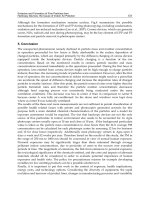
Figure 8.18 Anechoic chamber test facility for measuring antenna radiation patterns. The walls
are lined with pyramidal absorber. The antenna under test (AUT) is rotated around a vertical axis
while illuminated by the standard gain antenna (SGA).
272 Thiel
© 2006 by Taylor & Francis Group, LLC
Radiation pattern for switched parasitic antennas shown in Fig. 8.16.
It is possible to arrange a continuous rather than discrete switching operation by
changing the capacitive load at the center of the parasitic elements. This can be achieved
using variable reactive loads [8]. This allows for a more continuous scan of the beam, but
with potentially increased variation of the input impedance of the antenna.
Smart antennas must be controlled using a computer or microprocessor in
a feedback loop. The SNI ratio into the detector needs to be determined during a scan
of all possible main beam directions (a global scan), and then the signal source tracked
using a dithering procedure (i.e., by checking the SNI in adjacent main beam positions)
together with prediction techniques should the source or receiving antenna be moving. The
response time of the smart antenna is dependent on the switching speed, the detector
settling speed and the time required to verify the identification of the required source [5].
Two-dimensional phased arrays can have a main beam variation in both and
0 directions, while the switched parasitic antennas are most commonly limited to control
in one angular direction. The SNI is sometimes achieved with a large beamwidth
antenna by positioning a sharp null in the direction of a strong interfering noise source
rather than simply seeking the strongest signal. In a 2D phased array, the search procedure
can be quite complex and the computation time required for the calculations may be
significant. This is an active research area for digital processing specialists. Direction
finding algorithms include the MUSIC technique used for multiple source location an d
tracking.
8.6. ANTENNA MEASUREMENTS
Following antenna fabrication, the radiation F(0,) and impedance Z( f ) descriptions of
an antenna system usually must be verified experimentally. While there is now an exten-
sive number of computer modeling packages and techniques that allow the accurate
calculation of these parameters [3], variations in machining tolerances, the effects of finite
conductivity and dielectric loss, and increasing problems associated with the spurious
generation of intermodulation frequencies in adjacent frequency bands ensure that
antenna testing remains very important.
When planning antenna measurements, there are several important factors to be
considered [9]. The antenna performance must be isolated from its supporting structures
unless they are to be part of the final installation environment. This commonly means that
all objects (both conductive and dielectric) must be located away from the antenna by
several Fresnel zones [1]. The first Fresnel zone is defined as the region of space in which
the direct radiation path and any possible reflection path differ in length by less than l/2.
The second zone has reflections from a distance greater than l/2 and less than l. Higher
order Fresnel zones follow this definition with the reflection path length increasing by l/2
for the next Fresnel zone. Clearly, objects located in the near field of the radiating
structure will influence both F(0,) and Z( f ). This general principle applies to ground
reflections, side wall and ceiling reflections, in addition to the effects of feed cables to both
the transmitter and receiver, and the antennas themselves. For this reason, for an antenna
with a maximum aperture dimension of D > l, the separation distance between the two
antennas d must be greater than that given by the equation [9]
d >
2D
2
l
ð8:9Þ
Antennas : Funda ment a l s 273
© 2006 by Taylor & Francis Group, LLC
noting that D must be the maximum aperture dimension for both antennas. Secondly, the
antennas should be at the same height h above a reflecting ground plane where [9]
h > 4D ð8:10Þ
Given these two restrictions, antenna measurements are generally made in an
open range (i.e., no obstacles apart from the ground for many Fresnel zones) or in a
chamber lined with EM absorbing materials—an anechoic chamber. A number of such
materials are available commercially including pyramidal cones made from carbon
impregnated foam [2] and flat ceramic tiles. Both are limited to particular frequency
bands. In the case of radiation patterns with very large differences between the lobes and
nulls (e.g., high-gain antennas), the finite reflections from these absorbing tiles can affect
results significantly.
The gain of an antenna can be determined using two standard gain antennas
(SGA) and the antenna under test (AUT), or two identical AUT’s. The procedure requires
the feed cables to both the transmitting antenna and the receiving antenna to be
disconnected from the antennas and shorted together. The vector network analyzer is then
calibrated for zero insertion loss and the received power P
sc
noted for every frequency of
interest. The two identical antennas (SGAs or AUTs) are separated by distance d
1
where
d
1
> d and d is defined by Eq. (8.9), and the received power P is again noted. The free-space
path, loss P
L
is given by the expression
P
L
¼ 20 log
2%d
1
l
ð8:11Þ
If all values are in dB, the gain of the identical antennas G
i
in dB is given by the expression
G
i
¼
P þ P
L
P
sc
2
ð8:12Þ
In the standard gain horn measurement, the gain of the AUT (G
a
) is measured from a
power measurement taken from the SGA () AUT measurement P
d
using the following
calculation:
G
a
¼ P þ P
L
P
sc
G
sc
ð8:13Þ
where G
sc
is the gain of the SGA. These gain determinations include the antenna mismatch
S
11
for both antennas. A simple, yet very sensitive, test to verify that the antennas are
identical is to compare the S
11
( f ) for both antennas.
The input impedance of the antenna is calculated with the antenna in free space or
in an anechoic chamber. Initially the effects of the cable must be removed from the
calculation. This requires a three-po int calibration procedure across the frequency range
of interest. A high quality short-circuit, open-circuit, an d matched load termination must
be sequentially applied to the vector network analyzer (VNA) and the reflected field
strength (amplitude and phase) noted at every frequency. These measurements can be
designated À
s
, À
o
,andÀ
0
, respectively. The AUT is then attached to the end of the
cable, and À
a
measured. The impedance of the antenna is then determined mathematically.
27 4 Thiel
© 2006 by Taylor & Francis Group, LLC
if the antenna is to be rotated about a vertical axis (see Fig. 8.18).
The accuracy of the measurement depends strongly on the quality of the loads used in the
calibration procedure in addition to the noise environment surrounding the antenna [2].
Commonly the calibration procedures are an intrinsic part of the operation of a
VNA, and the user is prompted for the appropriate connections during the cali bration
procedure.
REFERENCES
1. IEEE Standard Definitions of Terms for Antennas; IEEE Press: Piscataway, NJ, IEEE Std
145-1993.
2. Balanis, C.A. Antenna Theory Analysis and Design; 2nd Ed.; Wiley: New York, 1997.
3. Stutzman, W.L.; Thiele, G.A. Antenna Theory and Design; 2nd Ed.; Wiley: New York, 1998.
4. Kraus, J.D. Antennas; 2nd Ed.; McGraw-Hill: New York, 1988.
5. Thiel, D.V.; Smith, S.A. Switched Parasitic Antennas for Cellular Communications; Artech
House: Boston MA, 2001.
6. Brown, E.R. RF-MEMs switches for reconfigurable integrated circuits. IEEE Trans. Microwave
Theory and Techniques 1998, 46, 1868–1880.
7. Goldsmith, C.L.; Yao, Z.; Eshelman, S.; Denniston, D. Performance of low-loss RF-MEMs
capacitive switches. IEEE Microwave Guided Wave Lett. 1998, 22, 269–271.
8. Harrington, R.F. Reactively controlled directive arrays. IEEE Trans. Antennas Propag. 1978,
26, 390–395.
9. IEEE Antenna Standards Committee. IEEE standard test procedures for antennas. ANSI/IEEE
Std 149-1979.
Antennas : Funda ment a l s 275
© 2006 by Taylor & Francis Group, LLC