GSM Networks : Protocols, Terminology, and Implementation - Chapter 4 potx
Bạn đang xem bản rút gọn của tài liệu. Xem và tải ngay bản đầy đủ của tài liệu tại đây (329.76 KB, 8 trang )
4
The Network Switching Subsystem
The NSS plays the central part in every mobile network. While the BSS pro-
vides the radio access for the MS, the various network elements within the NSS
assume responsibility for the complete set of control and database functions
required to set up call connections using one or more of these features: encryp-
tion, authentication, and roaming. To satisfy those tasks, the NSS consists of
the following:
•
MSC (mobile switching center);
•
HLR (home location register)/authentication center (AuC);
•
VLR (visitor location register);
•
EIR (equipment identity register).
The subsystems are interconnected directly or indirectly via the worldwide SS7
network. The network topology of the NSS is more flexible than the hierarchi-
cal structure of the BSS. Several MSCs may, for example, use one common
VLR; the use of an EIR is optional, and the required number of subscribers
determines the required number of HLRs.
Figure 4.1 provides an overview of the interfaces between the different
network elements in the NSS. Note that most interfaces are virtual, that is, they
are defined as reference points for signaling between the network elements.
31
4.1 Home Location Register and Authentication Center
Every PLMN requires access to at least one HLR as a permanent store of data.
The concept is illustrated in Figure 4.2. The HLR can best be regarded as
a large database with access times that must be kept as short as possible. The
faster the response from the database, the faster the call can be connected. Such
a database is capable of managing data for literally hundreds of thousands
subscribers.
Within the HLR, subscriber-specific parameters are maintained, such as
the parameter K
i
, which is part of security handling. It is never transmitted on
any interface and is known only to the HLR and the SIM, as shown in
Figure 4.2.
Each subscriber is assigned to one specific HLR, which acts as a fixed
reference point and where information on the current location of the user is
stored. To reduce the load on the HLR, the VLR was introduced to support the
HLR by handling many of the subscriber-related queries (e.g., localization and
approval of features).
Because of the central function of the HLR and the sensitivity of the
stored data, it is essential that every effort is taken to prevent outages of
the HLR or the loss of subscriber data.
The AuC is always implemented as an integral part of the HLR. The rea-
son for this is that although GSM mentions the interface between the AuC and
the HLR and has even assigned it a name, the H-interface, it was never speci-
fied in sufficient detail to be a standalone entity. The only major function
assigned to the AuC is to calculate and provide the authentication-triplets, that
32 GSM Networks: Protocols, Terminology, and Implementation
EIR
HLR
VLRVLR
E-interface
MSC G-MSC
B-interface
BSSs
G-interface
C-interface
C-interface
F-interface
F-interface
D-interface
D-interface
B-interface
External
connections
Figure 4.1 The NSS.
is, the signed response (SRES), the random number (RAND), and K
c
. For each
subscriber, up to five such triplets can be calculated at a time and sent to the
HLR. The HLR, in turn, forwards the triplets to the VLR, which uses them as
input parameters for authentication and ciphering.
The Glossary provides a detailed description of the authentication
procedure.
4.2 Visitor Location Register
The VLR, like the HLR, is a database, but its function differs from that of the
HLR While the HLR is responsible for more static functions, the VLR provides
dynamic subscriber data management. Consider the example of a roaming sub-
scriber. As the subscriber moves from one location to another, data are passed
between the VLR of the location the subscriber is leaving (“old” VLR) to the
VLR of the location being entered (“new” VLR). In this scenario, the old VLR
hands over the related data to the new VLR. There are times when the new
VLR has to request the subscriber’s HLR for additional data.
This question then arises: Does the HLR in GSM assume responsibility
for the management of those subscribers currently in its geographic area? The
answer is no. Even if the subscriber happens to be in the home area, the VLR of
that area handles the dynamic data. This illustrates another difference between
the HLR and the VLR. The VLR is assigned a limited geographical area, while
the HLR deals with tasks that are independent of a subscriber’s location. The
The Network Switching Subsystem 33
subscriber A: Ki 12345678
subscriber B: Ki 23415670
subscriber C: Ki 98753013
=
=
=
HLR
GSM SIM
.
.
.
.
.
GSM SIM
.
.
.
.
.
GSM SIM
.
.
.
.
.
Ki 23415670=
Ki 12345678=
Ki 98753013=
Figure 4.2 Only the SIM and the HLR know the value of K
i
.
term HLR area has no significance in GSM, unless it refers to the whole
PLMN. Typically, but not necessarily, a VLR is linked with a single MSC. The
GSM standard allows, as Figure 4.3 illustrates, the association of one VLR with
several MSCs.
The initial intentions were to specify the MSC and the VLR as independ-
ent network elements. However, when the first GSM systems were put into
service in 1991, numerous deficiencies in the protocol between the MSC and
the VLR forced the manufacturers to implement proprietary solutions. That
is the reason the interface between the MSC and the VLR, the B-interface, is
not mentioned in the specifications of GSM Phase 2. GSM Recommendation
09.02 now provides only some basic guidelines on how to use that interface.
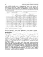
Table 4.1 lists the most important data contained in the HLR and
the VLR.
4.3 The Mobile-Services Switching Center
From a technical perspective, the MSC is just an ordinary Integrated Services
Digital Network (ISDN) exchange with some modifications specifically
required to handle the mobile application. That allows suppliers of GSM sys-
tems to offer their switches, familiar in many public telephone networks, as
MSCs. SIEMENS with its EWSD technology and ALCATEL with the S12
and the E10 are well-known examples that benefit from such synergy.
34 GSM Networks: Protocols, Terminology, and Implementation
VLR
VLR
VLR
HLR
HLR
MSC
MSC
MSC
MSC
MSC
Figure 4.3 The NSS hierarchy.
The modifications of exchanges required for the provision of mobile serv-
ice affect, in particular, the assignment of user channels toward the BSS, for
which the MSC is responsible, and the functionality to perform and control
The Network Switching Subsystem 35
Table 4.1
The Most Important Data in the HLR and the VLR
Parameter HLR/AuC VLR
Subscriber specific:
IMSI ●●
K
i
●
TMSI ●
Service restrictions ●
Supplementary services ●●
MSISDN (basic) ●●
MSISDN (other) ●
Authentication and ciphering:
A3 ●
A5/X (in BSS)
A8 ●
RAND up to five triplets ●●
SRES up to five triplets ●●
K
c
up to five triplets ●●
CKSN ●
Subscriber location/call forwarding:
HLR number ●
VLR number ●
MSC number ●●
LAI ●
IMSI detach ●
MSRN ●
LMSI ●●
Handover number ●
inter-MSC handover. That defines two of the main tasks of the MSC. We have
to add the interworking function (IWF), which is needed for speech and non-
speech connections to external networks. The IWF is responsible for protocol
conversion between CC and the ISDN user part (ISUP), as well as for rate
adaptation for data services.
4.3.1 Gateway MSC
An MSC with an interface to other networks is called a gateway MSC.
Figure 4.4 shows a PLMN with gateway MSCs interfacing other networks.
Network operators may opt to equip all of their MSCs with gateway function-
ality or only a few. Any MSC that does not possess gateway functionality has to
route calls to external networks via a gateway MSC.
The gateway MSC has some additional tasks during the establishment of
a mobile terminating call from an external network. The call has to enter the
PLMN via a gateway MSC, which queries the HLR and then forwards the call
to the MSC where the called party is currently located.
4.3.2 The Relationship Between MSC and VLR
The sum of the MSC areas determines the geographic area of a PLMN. Look-
ing at it another way, the PLMN can be considered as the total area covered by
the BSSs connected to the MSCs. Since each MSC has its “own” VLR, a
36 GSM Networks: Protocols, Terminology, and Implementation
PLMN
PSTN, ISDN, CSPDN, PSPDN
PSTN, ISDN, CSPDN, PSPDN
PSTN, ISDN, CSPDN, PSPDN
MSC
MSC
MSC
MSC
MSC
G-MSC
G-MSC
G-MSC
Figure 4.4 The functionality of the gateway MSC.
PLMN also could be described as the sum of all VLR areas. Note that a VLR
may serve several MSCs, but one MSC always uses only one VLR. Figure 4.5
illustrates this situation.
That relationship, particularly the geographic interdependency, allows for
the integration of the VLR into the MSC. All manufacturers of GSM systems
selected that option, since the specification of the B-interface was not entirely
available on time. In GSM Phase 2, the B-interface is no longer an open inter-
face (as outlined above). It is expected that this trend will continue.
A network operator still has the freedom to operate additional MSCs with
a remote VLR, but that is somewhat restrictive in that all the MSCs must be
supplied by the same manufacturer.
4.4 Equipment Identity Register
The separation of the subscriber identity from the identifier of the MS
(described in Chapter 2) also bears a potential pitfall for GSM subscribers.
Because it is possible to operate any GSM MS with any valid GSM SIM, an
opportunity exists for a black market in stolen equipment. To combat that, the
EIR was introduced to identify, track, and bar such equipment from being used
in the network.
Each GSM phone has a unique identifier, its IMEI, which cannot be
altered without destroying the phone. The IMEI contains a serial number and a
The Network Switching Subsystem 37
VLR area
VLR area
MSC area
MSC area
MSC
area
MSC area
MSC area
MSC
area
MSC
area
MSC
area
MSC
area
MSC
area
VLR area
VLR area
VLR area
VLR area
One PLMN seen as a
total of its VLR areas total of its MSC areas
Figure 4.5 Geographic relationship between the MSC and the VLR.
type identifier. More detailed description of the structure of the IMEI is given
in the Glossary.
Like the HLR or the VLR, the EIR basically consists of a database, which
maintains three lists: (1) the “white list” contains all the approved types of
mobile stations; (2) the “black list” contains those IMEIs known to be stolen or
to be barred for technical reasons; and (3) the “gray list” allows tracing of the
related mobile stations.
The prices for mobile equipment have fallen dramatically due to the great
success of GSM; consequently, the theft rate is low. Several GSM operators
have decided not to install the EIR or, at least, to postpone such installation for
a while.
If the EIR is installed, there is no specification on when the EIR should be
interrogated. The EIR may be queried at any time during call setup or location
update. Chapter 12 describes this in detail.
38 GSM Networks: Protocols, Terminology, and Implementation
White list
Black list Gray list
Contains all
approved types of
mobile equipment
(type approval codes)
Contains all
mobile equipment
to be barred
(complete IMEI)
Contains all
mobile equipment
to be traced
(complete IMEI)
Figure 4.6 Contents of the EIR.