PHYSICS 3 (ELECTRICITY AND MAGNETISM) - CHAPTER 4 docx
Bạn đang xem bản rút gọn của tài liệu. Xem và tải ngay bản đầy đủ của tài liệu tại đây (416.02 KB, 15 trang )
Electricity and Magnetism
38
Chapter 4
MAGNETISM
4.1 The Magnetic field
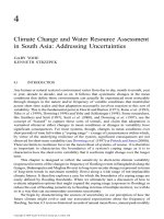
The most familiar source of magnetic fields is a bar magnet. One end of the bar magnet is called the North
pole and the other, the South pole. If we place some compasses near a bar magnet, the needles will align
themselves along the direction of the magnetic field, as shown in Fig. 4.1. The observation can be
explained as follows: A magnetic compass consists of a tiny bar magnet that can rotate freely about a
pivot point passing through the center of the magnet. When a compass is placed near a bar magnet which
produces an external magnetic field, it experiences a torque which tends to align the north pole of the
compass with the external magnetic field.
Fig. 4.1 Fig. 4.2 : Magnetic field of a bar magnet
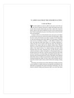
When two magnets or magnetic objects are close to each other, there is a force that attracts the poles
together. When two magnetic objects have like poles facing each other, the magnetic force pushes them
apart (Fig. 4.3). Magnets also strongly attract ferromagnetic materials such as iron, nickel and cobalt.
Fig. 4.3 Like poles repel, opposite poles attract
Fig. 4.4
Magnetic field lines : Magnetic field lines emanate primarily from the north pole of a magnet and curve
around to the south pole.
Electricity and Magnetism
39
The Earth’s magnetic field behaves as if there were a bar magnet in it (Fig. 4.5). Note that the south pole
of the magnet is located in the northern hemisphere.
Fig. 4.5 : Magnetic field of the Earth Fig. 4.6:The iron filings suggest
the magnetic field line of a bar magnet
4.2 Motion of a Charged Particle in a Uniform Magnetic Field
1) The Lorentz force
Consider a test particle with charge q moving through the magnetic field
B
r
with the velocity
v
r
. The
Lorentz force is
BxvqF
B
r
v
r
=
(4.1)
The SI unit for B is the Tesla (T) : 1T = 1 N/(Am) = 10
4
Gauss.
The right-hand rule gives the direction of a vector resulting from the cross product of two other vectors.
To find the direction of the resulting vector sweep the fingers of the right hand from the direction of the
first vector to the direction of the second vector over the smallest possible angle between the vectors. The
direction in which the thumb points is the direction of the resulting vector.
Fig. 4.7 : The right-hand rule
2) A charged particle circulating in a magnetic field
(Fig. 4.8)
A charge particle with mass m and charge magnitude |q| moving with velocity
v
r
perpendicular to a
uniform magnetic field
B
r
will travel in a circle of radius r
r
mv
vB|q|
2
=
⇒
r =
B|q|
mv
(4.2)
The frequency of the revolution
Electricity and Magnetism
40
f =
π
ω
2
=
T
1
=
r
2
v
π
=
m
2
B|q|
π
(4.3)
Fig. 4.8 Fig. 4.9
4.3 Magnetic Force Acting on a Current-Carrying Conductor (Fig. 4.9)
Consider a length L of the wire in Fig. 4.9. The amount of charge moving through the wire
q = it = iL/v
(v : drift speed)
⇒
F
B
= qvBsin(
ϕ
) = iLBsin(
ϕ
)
(
ϕ
: angle v, B)
A straight wire carrying a current i in a uniform magnetic field experiences a sideways force
BxLiF
B
r
r
r
=
(4.4)
the direction of the length vector
L
r
is that of the current i. (The length vector
L
r
has magnitude |
L
r
| = L
and is directed along the wire segment in the direction of the current.)
Exercise:
The mass spectrometer is shown in the following figure in which it shows an
arrangement used to measure the masses of ions. An ion of mass m and charge +q is produced
essentially at rest in source S, a chamber in which a gas discharged is taking place. The ion is
accelerated by potential difference V and allowed to enter a magnetic field
B
r
. In the field it
moves in a semicircle, striking a photographic plate at distance x from the entry slit. Show that
the ion mass m is given by
2
2
B q
m= x
8V
.
Electricity and Magnetism
41
4.4 Torque on a Current Loop in a Uniform Magnetic Field
A coil (of area A and N turns, carrying current i) in a uniform magnetic field
B
r
will experience a torque
τ
r
given by
Bx
r
r
r
µ=τ
(4.5)
here
µ
r
is the magnetic dipole moment of the coil, with magnitude
µ
= NiA and direction given by the
right hand rule (grasp the coil with the fingers of the right hand in the direction of the current i, the thumb
point to the direction of
µ
r
(Fig. 4.10).
Fig. 4.10
4.5 The Hall effect
Fig. 4.11 : a strip of copper carrying a current i is immersed in a magnetic field B. The charges (electrons)
will experience a deflecting force F
B
. Under the effect of the force F
B
, the electrons will be pushed toward
the right edge of the strip, leaving uncompensated positive charges in fixed positions at the left edge. An
electric field E is produced within the strip, pointing from left to right. The electric field exerts an electric
force F
E
on each electron, tending to push it to the left. An equilibrium is established when the electric
force cancels the magnetic force.
The Hall potential difference
V = Ed
When the electric force and the magnetic force are in balance
eE = ev
d
B
Electricity and Magnetism
42
Where v
d
is the drift speed : |v
d
| =
neA
i
A : cross-sectional area of the strip, n : number of charge per unit volume.
a b c
Fig. 4.11
4.6 The Biot-Savart Law
1) The magnetic field set up by a current-carrying conductor can be found from the Biot-Savart Law : The
contribution
Bd
r
to the field produced by a current element
sid
r
at a point P located a distance r from the
current element is
3
o
r
rxsid
4
Bd
r
r
r
π
µ
= (4.6)
Here
r
r
is a vector that points from the element to P. The quantity
µ
o
= 4
π
x10
-7
Tm/A
≈
1.26x10
-6
called
the permeability constant.
Fig. 4.12
2) Magnetic Field of a Long Straight Wire
(Fig. 4.13)
Biot-Savart law
Electricity and Magnetism
43
⇒
2
o
r
4
)sin(ids
dB
π
θ
µ
=
with r =
22
Rs +
and sin(
θ
) = sin(
π
-
θ
) =
22
Rs
R
+
⇒
∫
∞
π
θµ
=
0
2
o
ds
r
4
)sin(i
2B
=
∫
∞
+
π
µ
0
2/322
o
ds
)Rs(
R
2
i
=
R
2
i
o
π
µ
[T] (4.7)
Fig. 4.13 Fig. 4.14
3) Magnetic field due to a current in a circular arc of wire
(Fig 4.14)
Arc-shaped wire with central angle
Φ
, radius R, center C, carrying current i
B =
R
4
i
o
π
Φ
µ
[T] (4.8)
4) Force Between Two Parallel Currents
Two parallel wires carrying currents in the same direction attract each other (Fig. 4.15)
•
••
•
B
a
is the magnetic field at wire
b
produced by the current in wire a.
•
••
•
F
ba
is the resulting force acting on wire
b
because it carries current in field
B
a
.
Fig. 4.15 Fig. 4.16
In Fig. 4.16, the system of two current carrying wires is viewed in the direction of the currents. With the
currents perpendicular to the plane of the drawing and directed "into" the plane, the magnetic field created
by current i
a
circulates along (is tangent in clockwise direction to) circles centered at current i
a
. The figure
shows the direction of this magnetic field
B
a
at the location of current i
b
.
The magnitude of B
a
at every point of wire b is :
Electricity and Magnetism
44
B
a
=
d
2
i
ao
π
µ
(4.9)
The force F
ba
on a length L of wire b due to the external magnetic field B
a
is
abba
BxLiF
r
r
r
=
(4.10)
Since L and B
a
are perpendicular to each other
F
ba
=
d
2
iLi
bao
π
µ
(4.11)
Parallel currents attract each other. Antiparallel currents repel each other.
4.7 Ampere’s Law
1) Ampere’s Law
: Consider Fig. 4.17
∫
sdB
r
r
=
µ
o
i (4.12)
i = i
2
– i
1
(4.13)
Fig. 4.17 Fig. 4.18 Fig. 4.19
2) Magnetic field outside a long straight wire with current
(Fig. 4.18).
∫
sdB
r
r
= 2
π
rB =
µ
o
i
⇒
r
2
i
B
o
π
µ
=
(4.14)
3) Magnetic field inside a long straight wire with current
(Fig. 4.19).
2
o
R
2
ir
B
π
µ
=
(4.15)
4.8 The Magnetic Field of a Solenoid
1) Solenoid
Ampere’s law (Fig. 4.20)
Electricity and Magnetism
45
∫
sdB
r
r
= Bh =
µ
o
i
enc
=
µ
o
nhi
⇒
B =
µ
o
ni (4.16)
n : number of turns per unit length
Fig. 4.20 Fig. 4.21 Fig. 4.22
2) Toroid
Ampere’s law (Fig. 4.21)
∫
sdB
r
r
= B2
π
r =
µ
o
i
enc
=
µ
o
Ni
⇒
B =
r
2
Ni
o
π
µ
(4.17)
N : total number of turns
In contrast to the situation for a solenoid, B is not constant over the cross section of a toroid.
3) Current-Carrying coil as a Magnetic Dipole
(Fig. 4.22)
Biot-Savart law
⇒
⇒⇒
⇒
B =
(
)
2/3
22
2
o
zR2
iR
+
µ
(4.18)
4.9 Magnetic Flux. Gauss’s Law in Magnetism
1) The magnetic flux
Φ
B
through an area A in a magnetic field
B
r
is defined as
Φ
B
=
∫
A.dB
r
r
[Wb] (4.19)
where the integration is taken over the area.
2) Gauss’s Law in Magnetism
The net magnetic flux through any (closed) Gaussian surface is zero.
Φ
B
=
∫
A.dB
r
r
= 0 (4.20)
Electricity and Magnetism
46
⇒
The simplest magnetic structure that can exist is a magnetic dipole. Magnetic monopoles do not exist
.
4.10 Displacement Current and the General Form of Ampère’s Law
1) Maxwell’s law of induction
: a changing electric flux induces a magnetic field
B
r
∫
s.dB
r
r
=
µ
o
ε
o
dt
d
E
Φ
(4.21)
side view top view
Fig. 4.23 : A circular parallel plate capacitor is being charged by a constant current
Example
: A parallel plate capacitor with circular plates of radius R is being charged as in Fig. 12.1.
Derive an expression for the magnetic field at radius r
≤
R. Evaluate the field magnitude for r = R/5 =
11mm and dE/dt 1.5x10
12
V/ms. Derive an expression for the magnetic field at radius r > R.
r
≤
R : 2
π
rB =
µ
o
ε
o
dt
d
E
Φ
=
µ
o
ε
o
(
π
r
2
)
dt
dE
⇒
B =
µ
o
ε
o
2
r
dt
dE
r > R : 2
π
rB =
µ
o
ε
o
dt
d
E
Φ
=
µ
o
ε
o
(
π
R
2
)
dt
dE
⇒
B =
µ
o
ε
o
r
2
R
2
dt
dE
2) Ampere-Maxwell law
Ampere’s law
∫
s.dB
r
r
=
µ
o
i (4.22)
Combining (4.21) and (4.22) yields Ampere-Maxwell law
∫
s.dB
r
r
=
µ
o
i +
dt
d
E
oo
Φ
εµ
(4.23)
3) Displacement current
The quantity
i
d
=
dt
d
E
o
Φ
ε
(4.24)
Electricity and Magnetism
47
has the dimension of a current and is called the displacement current. Rewrite (4.23)
∫
s.dB
r
r
=
µ
o
i +
µ
o
i
d
(4.25)
Fig. 4.24 : i = i
d
The displacement current i
d
can be viewed as the continuation of the real current i (Fig.(12.2)). The
magnitude and the direction of the magnetic field produced by the displacement current i
d
is determined as
the one of the real current i.
Example
: The circular parallel plate capacitor in previous example is being charged with a current i.
Determine the magnetic field B at a radius r from the center. Assume that i
d
is uniformly spread over the
full plate area
∫
s.dB
r
r
=
µ
o
i
d
2
2
R
r
⇒
2
π
rB =
2
2
do
R
riµ
⇒
B =
2
do
R2
ri
π
µ
=
2
o
R2
ir
π
µ
(where the integration is taken over the circle of radius r.)
Problems
Magnetic field
4.1) A flexible wire, carrying a current i, passes between the pole faces of a magnet. Under the influence of the
magnetic field, the wire is deflected. Determine the direction of the current i in each case (Fig. P4.1)
i = 0 i
≠
0 Fig. P4.2
Fig. P4.1
Electricity and Magnetism
48
4.2) In Fig. P4.2, a metal wire of mass m = 25mg can slide with negligible friction on 2 horizontal parallel rails
separated by distance d = 4cm. The track lies in a vertical uniform magnetic field of magnitude 50mT. At
time t = 0, a source is connected to the rails, producing a constant current i = 10mA in the wire and rails
(even as the wire moves). At t = 50ms, what are the speed and the direction of motion of the wire.
4.3) An ion of mass m and charge q is produced in source S (Fig. P4.3). The initially stationary ion is
accelerated by the electric field due to a potential difference e. The ion leaves S and enters a separator
chamber in which a uniform magnetic field B is perpendicular to the path of the ion. The magnetic field B
causes the ion to move in a semicircle and thus strikes a detector at the bottom wall of the chamber.
Suppose that B = 80mT, e = 1000V, q = +1.6022x10
-19
C, x = 1.6254m. What is the mass m of the
individual ion ?
Fig. P4.3 Fig. P4.4
4.4) Magnetic levitation is used in high-speed trains. Conventional electronmagnetic technology is used to
suspend the train over the tracks; the elimination of rolling friction allows the train to achive very high
speeds (in excess of 400km/h). The principle of magnetic levitation can be given as the following
problem. A straight horizontal copper rod carries a current of 50.0 A from west to east in a region between
the poles of large electromagnet (Fig. P4.4). In this region there is a horizontal magnetic field toward the
north-east (that is, 45
o
north of east) with magnitude 1.20 T. Find
a) The magnitude and direction of the force on a 1.00-m section of rod.
b) If the horizontal rod is in mechanical equilibrium
under the action of its weight and the magnetic
force. What is the mass of the horizontal rod?
c) While keeping the rod horizontal, how should it be oriented to maximize the magnitude of the force.
d) What is the force magnitude and the mass of the rod in case (c).
4.5) Two concentric, circular wire loops, of radii r
1
= 12cm and r
2
= 10cm, are located in an xy plane, each
carries a clockwise current of 2A. Find the magnitude of the net magnetic dipole moment of the system
(Fig. P4.5A). Repeat for the reversed current in the outer loop (Fig. P4.5B).
A B Fig. P4.6
Fig. P4.5
Electricity and Magnetism
49
4.6) Consider a rectangular coil of wire in a magnetic field as shown in Fig. P4.6. The coil has height a and
width b. The current in the coil is i.
a) Find the force on each side of the coil.
b) As the rectangular wire rotates, the force on the sides AB and CD is non-zero. Does this effect the
rotation ?
c) Are the forces on sides BD and AC constant in magnitude throughout a given rotation ?
4.7) A solid metal cube of edge length d = 1.5cm, moving in the positive y direction at velocity v = 4m/s
through a uniform magnetic field B = 0.05T in the positive z direction (Fig. P4.5).
a) Which cube face is at a lower electric potential and which is at a higher electric potential ?
b) What is the potential difference between the faces of higher and lower electric potential ?
Fig. P4.7 Fig. P4.8
Magnetic field by an electric current
4.8) Find the magnetic field at point O in Fig. P4.8 where OA = 15cm, OB = 20cm,
θ
=
π
/3 rad, I = 1A.
4.9) Find the magnetic field at the center O of the semicircle in Fig. P4.9 where L = 12cm, R = 10cm.
Fig. P4.9 Fig. P4.10 Fig. P4.11
4.10) A conducting rectangle MNPQ (Fig.P4.10), carrying current I
2
, is placed near a long wire carrying current
I
1
. Find the net force on the rectangle due to I
1
.
4.11) Find the magnetic field at point P in Fig. P4.11.
Displacement Current and the General Form of Ampère’s Law
4.12) The magnitude of the electric field between the two circular parallel plates is E = 4x10
5
– 6x10
4
t V/s
(Fig. P4.12). The plate area is 4x10
-2
m
2
. Determine
a) the magnitude and the direction of the displacement current between the plates.
b) the magnitude and the direction of the induced magnetic field.
Electricity and Magnetism
50
Fig. P4.12 Fig. P4.13
4.13) Two wires, parallel to a z axis and a distance 2r apart, carry equal currents i in opposite directions as
shown in Fig. P4.13. A circular cylinder of radius r/2 and length L has it axis on the z axis, midway
between the wires. Use Gauss’ law for magnetism to derive an expression for the net outward magnetic
flux through the half of the cylindrical surface above the x axis. (Hint : find the flux through the portion of
the xz plane that lies within the cylinder.)
4.14) A capacitor C with circular plates of radius b. The distance between the two plates is d. Initially the
capacitor is charged to a voltage V
o
. At t = 0 the switch is closed and the capacitor discharges through the
resistor R (Fig. P4.14).
a) Find the charge Q as a function of time of the capacitor.
b) Find the electric field E, the magnetic field B and the displacement current i
d
between the capacitor
plates.
Fig. P4.14 Fig. P4.15
4.15) The capacitor C in Fig. P4.15 has circular plates of radius b. The space d between the two plates is small
compared to b so that we can ignore the fringing effects. Initially C is uncharged. At t = 0 the switch K is
closed and the capacitor charges through the resistor r.
a) Find the potential difference V and the current i of the circuit.
b) Find the electric field E, the magnetic field B and the displacement current i
d
between the capacitor
plates.
4.16)
Two square conducting loops carry currents of 5.0 A and 3.0 A as shown in Fig. P4.16.
What is
the value of the line integral
∫
sdB
r
r
for each of the two closed paths shown?
Fig P4.16
Electricity and Magnetism
51
Homeworks 4
H4.1 A solid metal cube of edge length d [cm], moving in the positive y direction at velocity v [m/s] through a
uniform magnetic field B [T] in the positive z direction (Fig. H4.1).
a) Which cube face is at a lower electric potential and which is at a higher electric potential ?
b) What is the potential difference between the faces of higher and lower electric potential ?
Fig. H4.1 Fig. H4.2 Fig. H4.3
n 1 2 3 4 5 6 7 8 9 10 11 12 13 14 15 16
d 2.1 2.2 2.3 2.4 2.5 2.6 2.7 2.8 2.9 3.1 3.2 3.3 3.4 3.5 3.6 3.7
v 2 3 4 5 6 7 8 9 2 3 4 5 6 7 8 9
B
0.01
0.02
0.03
0.04
0.05
0.06
0.07
0.08
0.09
0.01
0.02
0.03
0.04
0.05
0.06
0.07
n 17 18 19 20 21 22 23 24 25 26 27 28 29 30 31 32
d 2.1 2.2 2.3 2.4 2.5 2.6 2.7 2.8 2.9 3.1 3.2 3.3 3.4 3.5 3.6 3.7
v 3 4 5 6 7 8 9 2 3 4 5 6 7 8 9 3
B
0.04
0.05
0.06
0.07
0.08
0.09
0.01
0.02
0.03
0.04
0.05
0.06
0.07
0.04
0.05
0.06
n 33 34 35 36 37 38 39 40 41 42 43 44 45 46 47 48
d 2.1 2.2 2.3 2.4 2.5 2.6 2.7 2.8 2.9 3.1 3.2 3.3 3.4 3.5 3.6 3.7
v 4 5 6 7 8 9 2 3 4 5 6 7 8 9 2 3
B
0.07
0.08
0.09
0.01
0.02
0.03
0.04
0.05
0.06
0.07
0.04
0.05
0.06
0.07
0.08
0.09
n 49 50 51 52 53 54 55 56 57 58 59 60 61 62 63 64
d 2.1 2.2 2.3 2.4 2.5 2.6 2.7 2.8 2.9 3.1 3.2 3.3 3.4 3.5 3.6 3.7
v 5 6 7 8 9 2 3 4 5 6 7 8 9 2 3 4
B
0.02
0.03
0.04
0.05
0.06
0.07
0.04
0.05
0.06
0.07
0.08
0.09
0.02
0.03
0.04
0.05
H4.2 A conducting rectangle MNPQ (Fig.H4.2), carrying current I
2
, is placed near a long wire carrying current
I
1
. Find the net force on the rectangle due to I
1
(sizes are in cm, currents are in A).
n 1 2 3 4 5 6 7 8 9 10 11 12 13 14 15 16
a 22 24 26 28 30 32 34 36 38 42 44 46 48 50 52 54
b 11 12 13 14 15 16 17 18 19 21 22 23 24 25 26 27
d 5 6 7 8 9 11 12 13 14 15 16 17 18 19 20 21
I
1
5 10 15 20 25 30 35 40 45 50 55 60 65 70 75 80
I
2
1 2 3 4 5 6 7 8 9 10 11 12 13 14 15 16
Electricity and Magnetism
52
n 17 18 19 20 21 22 23 24 25 26 27 28 29 30 31 32
a 56 58 22 24 26 28 30 32 34 36 38 42 44 46 48 50
b 28 29 11 12 13 14 15 16 17 18 19 21 22 23 24 25
d 5 6 7 8 9 11 12 13 14 15 16 17 18 19 20 21
I
1
10 15 20 25 30 35 40 45 50 55 60 65 70 75 80 85
I
2
1 2 3 4 5 6 7 8 9 10 11 12 13 14 15 16
n 33 34 35 36 37 38 39 40 41 42 43 44 45 46 47 48
a 52 54 56 58 22 24 26 28 30 32 34 36 38 42 44 46
b 26 27 28 29 11 12 13 14 15 16 17 18 19 21 22 23
d 5 6 7 8 9 11 12 13 14 15 16 17 18 19 20 21
I
1
15 20 25 30 35 40 45 50 55 60 65 70 75 80 85 90
I
2
1 2 3 4 5 6 7 8 9 10 11 12 13 14 15 16
n 49 50 51 52 53 54 55 56 57 58 59 60 61 62 63 64
a 24 26 28 30 32 34 36 38 42 44 46 24 26 28 30 32
b 15 16 17 18 19 21 22 23 24 25 15 16 17 18 19 21
d 5 6 7 8 9 11 12 13 14 15 16 17 18 19 20 21
I
1
20 25 30 35 40 45 50 55 60 65 70 75 80 20 25 30
I
2
1 2 3 4 5 6 7 8 9 10 11 12 13 14 15 16
H4.3 The magnitude of the electric field between the two circular parallel plates is E =
α
t [V/s] (Fig. H4.3). The
plate area is A [m
2
]. Determine
a) the magnitude and the direction of the displacement current between the plates.
b) the magnitude and the direction of the induced magnetic field.
n 1 2 3 4 5 6 7 8 9 10 11 12 13 14 15 16
α
100 120 150 180 200 220 250 280 300 320 350 380 400 420 450 480
A
0.02
0.03
0.04
0.05
0.06
0.07
0.08
0.09
0.02
0.03
0.04
0.05
0.06
0.07
0.08
0.09
n 17 18 19 20 21 22 23 24 25 26 27 28 29 30 31 32
α
500 520 550 580 600 620 650 680 700 720 750 780 800 820 850 880
A
0.02
0.03
0.04
0.05
0.06
0.07
0.08
0.09
0.02
0.03
0.04
0.05
0.06
0.07
0.08
0.09
n 33 34 35 36 37 38 39 40 41 42 43 44 45 46 47 48
α
900 920 950 980 110 170 210 270 310 370 410 470 510 570 810 870
A
0.02
0.03
0.04
0.05
0.06
0.07
0.08
0.09
0.02
0.03
0.04
0.05
0.06
0.07
0.08
0.09
n 49 50 51 52 53 54 55 56 57 58 59 60 61 62 63 64
α
210 270 310 370 410 470 510 570 810 870 210 270 310 370 410 470
A
0.02
0.03
0.04
0.05
0.06
0.07
0.08
0.09
0.02
0.03
0.04
0.05
0.06
0.07
0.08
0.09