EC&M’s Electrical Calculations Handbook - Chapter 8 pps
Bạn đang xem bản rút gọn của tài liệu. Xem và tải ngay bản đầy đủ của tài liệu tại đây (390.25 KB, 28 trang )
Lighting
The Lumen Method
It is always valuable to keep in mind the definition of a foot-
candle: It is the quantity of lumens per square foot of illumi-
nated work surface. This definition alone provides the
lighting designer a quick rough estimate of the quantity of
lumens required to illuminate (fall on) a certain area: Take
the footcandle value and multiply it by the area in square feet:
Approximate lumen quantity falling on the area
ϭ footcandles ϫ area in square feet
A more accurate and easy approximation of the actual
lamp lumen requirement (how many lumens must be emit-
ted by the lamps within the luminaires) is also possible.
Note that some of the lamp lumens are trapped within the
fixture and do not reach the area to be illuminated. To pro-
vide for this inaccuracy, a determination is made of the
rough approximate total quantity of lumens required to illu-
minate the area; dividing the total lumen requirement by
the lumen output from each luminaire (typically one-half
the lamp lumens) provides a good estimate of the quantity
Chapter
8
221
v
Copyright 2001 by The McGraw-Hill Companies, Inc. Click here for Terms of Use.
of luminaires required to illuminate the area. One-half the
lamp lumens is a good estimate of the light emitted by each
fixture after the combination of luminaire coefficient of use
(CU) and light losses is considered:
Approximate lumen quantity emitted by lamps
ϭ
or, stated in another way,
Approximate lumen quantity emitted by lamps
ϭ 2 ϫ (footcandles ϫ area in square feet)
This quick calculation method is also a good method of
checking intensive manual calculations or computer calcu-
lations to see if their results are reasonable.
From this basic logic, the following lumen method of cal-
culation formulas are derived:
Luminaire quantity ϭ
footcandles ϫ area in square feet
(lumens/lamp) (lamps/fixture)
(fixture CU) (maintenance factor)
The footcandle illuminance determination can be made from
a known area and known lighting layout in this way:
Footcandles ϭ
(no. of fixtures) (lumens/lamp)
(lamps/fixture) (fixture CU)
(maintenance factor)
area in square feet
For example, if a 10,000-square-foot (ft
2
) area is to be illu-
minated by lamps whose lumen output is 2500 lumens per
lamp and the type of luminaire and maintenance factors are
unknown (except that it is known that one luminaire will
contain one lamp), the approximate quantity of luminaires
required to achieve an illuminance of 5 fc will be
footcandles ϫ area in square feet
ᎏᎏᎏᎏ
0.50
222 Chapter Eight
Luminaire quantity ϭ
ϭ 40 single-lamp luminaires
The definitions and finer points of maintenance factors and
fixture CUs are discussed in detail later in this chapter and
in Chap. 10.
The lumen method does not give an indication of what the
footcandle level will be at any one specific point or worksta-
tion. For this, it is necessary to use the point-by-point method.
The Point-by-Point Method
How to make point-by-point calculations
Later in this chapter, lighting calculations within areas hav-
ing reflective surfaces, such as interior walls, are shown and
(5 fc) ϫ (10,000 ft
2
)
ᎏᎏᎏᎏ
(2500 lumens per lamp) (1) (0.5)
Lighting 223
High-mast lighting can provide even illuminance levels.
explained. However, where no reflective surfaces exist, all
the light falling on the work surface must be provided
directly from the luminaires shining on the work surface,
and the method of manual lighting calculation that is most
accurate for points on the work surface is known as the
point-by-point method of lighting calculation (also known as
the point-to-point method). This method is also used most
often when light at specific locations on the work surface
must be known and for floodlighting calculations.
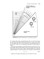
Direct lighting diminishes inversely as the distance
squared. This relationship can be used to determine the illu-
mination level, or footcandle level, at a specific point, for
with this relationship the footcandle value can be calculated
from the candlepower directed toward that point, the dis-
tance from that point to the light source, and the angle of
incidence the light rays make with the lighted surface.
When the light rays are not falling perpendicularly onto
the lighted surface, the full impact of the light is not available
to illuminate the surface. Exactly how much illumination will
result is easily determined by these two relationships:
1. Footcandles measured at the work surface with the
lightmeter laid flat on the work surface are equal to the can-
dlepower (CP) intensity multiplied by the excluded angle
made by the light ray and the work surface divided by the
square of the distance between the luminaire and the point
on the work surface:
Footcandles ϭ
Note that the angle
is the excluded angle that the light ray
makes with the work surface or with the face of an imaginary
lightmeter laid flat on the work surface.
2. Note that for “normal” footcandle values, the face of the
lightmeter is perpendicular to the light ray, so the angle
that the light ray makes with the face of the lightmeter is
zero, and the cosine of zero is 1.0 . Therefore, for footcandle
values immediately below the centerline of a luminaire
(known as at nadir), this formula simplifies to
CP ϫ cos
ᎏᎏᎏ
(distance in feet)
2
224 Chapter Eight
Footcandles ϭ
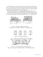
The left side of Fig. 8-1 shows a completed sample problem
solving for normal footcandle values for the case directly
below (at nadir) the luminaire.
To understand how these equations are used, it is neces-
sary to know the following definitions and concepts:
1. Distance in point-by-point calculations is the quantity
of feet between the lighting fixture and the point at which
an imaginary lightmeter is placed at the work surface to be
illuminated.
2. Candlepower is the value of light intensity emitted by
the lighting fixture in the direction formed by a line between
the center of the lamp and the center of the imaginary light-
meter.
3. The lighting calculations result in footcandle illumi-
nation values that would be displayed on an imaginary foot-
candle lightmeter located at the illumination point on the
work surface. The lightmeter would be positioned so that its
photocell pickup transducer would be parallel to the plane of
the work surface rather than perpendicular to the ray of
light coming from the luminaire.
4. Unless specifically stated otherwise in a given prob-
lem, light illuminance is stated in horizontal footcandles.
Horizontal footcandles are the measure of light falling per-
pendicularly onto a horizontal surface.
The quantity of horizontal footcandles is equal to the can-
dlepower emitted by the luminaire in the exact direction of
the point on the surface to be lighted multiplied by the cosine
of the angle the light ray makes with the surface to be light-
ed and divided by the square of the distance between the
luminaire and the point on the surface to be lighted.
It is not necessary that the lighting designer be a mathe-
matician skilled in trigonometry, but rather that the light-
ing designer simply understand that the light ray is not
hitting the work surface squarely. Compensation must be
made for this by multiplying the lighting intensity value by
CP
ᎏᎏᎏ
(distance in feet)
2
Lighting 225
Figure 8-1
Solve for “normal” vertical and horizontal footcandles
using the
point method given candlepower intensity, height,
and distance or angle.
226
the factor every scientific calculator will show when the
angle is entered and the “COS” key is depressed.
5. When it is specifically stated within a given problem
that the lighting designer is to solve for a light intensity hit-
ting a facia, a sign, the side of a building or tank, or some
other vertical surface, the light intensity must be solved in
vertical footcandles. Vertical footcandles are the measure of
light falling perpendicularly onto a vertical surface, similar
to light from an automobile headlight illuminating a garage
door.
The quantity of vertical footcandles is equal to the can-
dlepower emitted by the luminaire in the exact direction of
the point on the surface to be lighted multiplied by the sine
of the angle the light ray makes with the surface to be lighted
and divided by the square of the distance between the lumi-
naire and the point on the surface to be lighted.
Again, it is not necessary that the lighting designer be a
mathematician skilled in trigonometry, but rather that the
lighting designer simply understand that the light ray is not
hitting the work surface squarely. Compensation must be
made for this by multiplying the lighting intensity value by
the factor that every scientific calculator will show when the
angle is entered and the “SIN” key is depressed.
6. The point directly under a lighting fixture that is
aimed directly downward is known as nadir.
7. Candlepower emitted from a fixture at any one angle
from nadir does not represent the candlepower emitted at
any other angle.
8. All frequencies of light follow the same intensity and
formula calculations. Therefore, lighting intensity calcula-
tions simply ignore light color.
9. The angle is the angle formed between straight
down, known as nadir, and the line formed between the cen-
ter of the lamp and the center of the imaginary lightmeter
that is centered on the beam of light.
10. The candlepower values shown in luminaire photo-
metric data already include the fixture CU and efficiency;
therefore, in point-by-point calculations using candlepower
data, the fixture CU and efficiency can be ignored.
Lighting 227
And the last concept is the one on which all area lighting
calculations are based, so it can be considered to be possibly
the most important point of all.
11. If several luminaires contribute to the illumination at
a point, the resulting illumination is determined by making
an individual calculation of the horizontal footcandle contri-
bution by each individual luminaire and then summing these
contributions in a normal algebraic manner. For example, if
two luminaires shine on one certain point, the total horizon-
tal footcandle level at that point would be equal to the sum of
the horizontal footcandles from the first luminaire plus the
horizontal footcandles from the second luminaire.
Sample point-by-point lighting calculations
Refer to Fig. 8-1 for sample point-by-point lighting calcula-
tions for both the nadir point and a point that is not directly
below the fixture aimed in a downward direction where the
horizontal and vertical footcandle values must be determined.
The first sample calculation is as follows: What is the foot-
candle intensity immediately below the fixture? To solve this
228 Chapter Eight
High-mount fixtures are the most cost-effective way of lighting an
outdoor area.
problem, it is first necessary to note that the question has not
specifically asked for vertical footcandle intensity, and there-
fore, the final answer should be in horizontal footcandles.
Next, an inspection of the figure shows that the photo-
metric curves of the fixture have already been read, and
their values at key angles have been placed in table form
beside the sketch of the lighting fixture and the surface to
be illuminated. The formula incorporating the cosine func-
tion provides horizontal footcandles (important for lighting
a walkway), whereas the formula incorporating the sine
function provides vertical footcandles (important for light-
ing a wall).
Indoor Lighting
Zonal cavity method for indoor lighting
calculations
To be able to properly design lighting systems for indoor
locations, the lighting designer needs to understand the zon-
al cavity method of calculations and all the factors that
enter into them. This section details the zonal cavity method
of calculations, describes how these calculations are made,
and provides reference material such as reflectance values
for different colors and textures of interior surfaces.
Lighting is provided by two components:
■
Direct light
■
Reflected light
In all point-to-point calculations, only the direct-light com-
ponent is considered, and this is acceptable for use outdoors,
where few reflective surfaces exist.
When lighting calculations are made for indoor areas,
consideration of the reflected light is frequently needed for
more accuracy because of the large amount of reflected light
from the surfaces of rooms. The zonal cavity method of light-
ing calculations provides a way of calculating the sum of the
direct light and the reflected light, thus calculating all the
light that will shine on a work surface. The reflectances (in
Lighting 229
percent reflected lumens) of different colors and textures of
wall, ceiling, floor, and furniture surfaces (painted with flat
paint) are shown below:
Light red 70%
Dark red 21%
Light orange 68%
Dark orange 35%
Light yellow 82%
Light green 73%
Dark green 7%
Light blue 68%
Dark blue 8%
Light gray 65%
Dark gray 14%
As its name implies, the zonal cavity calculation method
suggests that there are certain cavities that are affected by
light or which affect the lighting within them. In this calcu-
lation methodology, there are three cavities in a room:
■
The room cavity (h
RC
)
■
The ceiling cavity (h
CC
)
■
The floor cavity (h
FC
)
Actually, one or more of these cavities may have no depth
and thus may be neglected within the calculation. See cal-
culation step E below for the steps to determine actual cav-
ity ratios.
Preparation steps and related information
A. Determine the mean footcandle level desired.
The footcan-
dle level desired for a given use can be determined by refer-
ring to specifications for the area, to illumination
engineering manuals, to life safety codes, or to the following
abbreviated suggested mean footcandle values:
230 Chapter Eight
Safety egress path 1 fc
General corridor pathway illumination 20 fc
Reading and general office tasks 75 fc
Drawing on tracing paper 200 fc
Background lighting in hospital operating room 500 fc
Paint shop lighting 500 fc
Lighting 231
Illumination for egress paths must be provided in manned instal-
lations.
Note that the issue of veiling reflections on cathode-ray
tube (CRT) screens must be considered when selecting the
luminaire and the lens or louver in the luminaire. That is,
every effort must be made in areas where computers will be
used to prevent the computer operator from seeing the
reflection of the luminaire in the CRT screen. Also, in cer-
tain offices, shiny glass desk tops are used. In these unusu-
al locations, luminaires whose photometric data resemble a
“bat wing” are required. With bat-wing lenses, almost all the
light is emitted at large angles from nadir, whereas almost
no light is emitted straight downward. A knowledge of the
planned use of the space to be lighted is necessary to make
a good lighting design.
B. Select the type of fixture and lamp to be used. This is done
from a vendor catalog or from operator-client details and
specifications. For example, frequently the lighting fixtures
used within an office space measure 2 ϫ 4 ft, mount into an
inverted-T lay-in ceiling, and are equipped with flat pris-
matic acrylic lenses and two, three, or four F32T8 lamps.
C. Determine initial lumens per lamp. This is done most easi-
ly from lamp manufacturer catalog data. Lamp catalogs
show a wealth of information about each lamp, including
■
The catalog number of the lamp
■
The energy use of the lamp in watts
■
The quantity of lamps that are packaged by the factory in
a standard case
■
The nominal length in inches and in millimeters
■
The initial light output in lumens
■
The mean light output in lumens
■
The average rated life in hours
■
The color temperature in degrees Kelvin
■
The color rendering index information in percent
■
Additional information about special phosphors or ambi-
ent temperatures
232 Chapter Eight
■
The type of lamp (e.g., fluorescent rapid-start medium
bipin)
■
The type of socket base into which the lamp is intended to
mount
A summary of data for some of the most frequently used
lamps is given in Fig. 8-2.
D. Calculate the light-loss factors. The initial lumen values
published within a catalog for a given lamp are based on cer-
tain ambient temperature levels and lamp aging criteria.
Also, not all the lumens emitted from the lamps escape from
the lighting fixture. Finally, dirt accumulation on the fixture
and on the lamps, as well as on the surfaces of the room,
absorbs some of the light. These must all be considered when
designing a lighting system:
1. Ambient temperature
■
Does not significantly affect high-intensity-discharge
(HID) output levels.
■
Does not affect incandescent output levels.
■
Affects fluorescent output levels when the ambient tem-
perature is warmer or colder than 77°F. For example, at
20°F, the output of fluorescent lamps is reduced to 40
percent.
■
See the second bulleted item under “Ballast Factor” below
for the results of extreme overtemperature.
2. Ballast factor. There are several issues concerning bal-
lasts that must be considered, but most of them can be sum-
marized as follows:
■
A “poor” fluorescent ballast causes decreased overall lumi-
naire performance, but this is most often ignored in light-
ing calculations. If ambient temperature can exceed
135°F during the hot summer months, then the thermal
element within Class P ballasts will open, initially deen-
ergizing the fixture. Ultimately (after approximately four
deenergization cycles), however, this will destroy the bal-
Lighting 233
Figure 8-2
Common lamps and their characteristics.
234
last unless system voltage can be reduced sufficiently to
offset the increased ambient temperature. If this is not
possible, then an anticipated quantity of ballasts that will
be deenergized at one time must be factored into the over-
all calculation. One item that affects the value of this fac-
tor is the type of maintenance program planned for the
facility.
■
The type of ballast used for an HID lamp greatly affects
lumen maintenance.
■
Base the design on standard voltage. If a nonstandard
voltage is to be used, then the output of the lamps must be
reduced. For example, fluorescent lamp output should be
reduced 5 percent for every 10 percent reduction in line
voltage.
3. Room surface dirt depreciation. Room surface dirt deprecia-
tion accounts for decreased wall reflectance when the walls
become aged or dirty. The following dirt depreciation factors
should be subtracted from 100 percent to obtain the dirt
depreciation factor (DDF) that is used in the zonal cavity
calculation formula:
0–12 percent loss Very clean
13–24 percent loss Clean
25–36 percent loss Medium
37–48 percent loss Dirty
49–60 percent loss Very dirty
4. Lamp lumen depreciation. This is one of the key parts of
the lighting calculation because it determines the output of
the lamps as they burn over time. This part of the calcula-
tion recognizes that
■
Aged lamps emit less light. For example, if fluorescent
lamps are not replaced after approximately three-quar-
ters of their rated life, their output is reduced to 66 per-
cent of initial lumen output. This reduction is even more
severe (reduction to 40 percent) when certain HID lamps
are used.
Lighting 235
■
As an alternative to entering the initial lamp lumen rating
and then the lamp lumen depreciation value into the cal-
culation, the lighting designer can instead enter the mean
lumen rating from the catalog data.
■
This section of the calculation must include a considera-
tion of whether “burned out” lamps will be replaced as they
236 Chapter Eight
Parking lot lighting using HID lamps.
die, or whether the passage of time will discover that at the
end of the mean lamp life curve, half the lamps in the facil-
ity will not be burning. If they will not be replaced as they
burn out, then a factor of 0.5 must be entered to accommo-
date this fact.
5. Luminaire dirt depreciation. If dirt is allowed to build up on
lighting fixture lenses and on the lamps, or if airflow is
directed over the lamps in the planned luminaire, then less
Lighting 237
Quartz tungsten lamps are useful where stroboscopic effect is not
permitted.
light will be emitted, and this must be accommodated with-
in the lighting calculation. Light emitted from the fixture is
reduced by 10 percent over time in “clean” environments, by
20 percent in typical industrial areas, and by 30 percent in
very dirty areas.
The total light-loss factor (often called the maintenance
factor) is the product of the factors shown above in items 1
through 5.
E. Calculate the cavity ratios. An individual calculation must
be made of the ceiling cavity, the floor cavity, and the room
cavity. The cavity ratios for each are calculated as follows:
Room cavity ratio: RCR ϭ
where h
RC
ϭ is the height of the room cavity, feet (ft)
L ϭ the length of the room cavity, ft
W ϭ width of the room cavity, ft
Ceiling cavity ratio: CCR ϭ
where h
CC
ϭ height of the ceiling cavity, ft
L ϭ length of the ceiling cavity, ft
W ϭ width of the ceiling cavity, ft
Note that if the fixtures are recessed, the ceiling cavity has
a height of zero, and RCR ϭ 0.
Floor cavity ratio: FCR ϭ
where h
FC
ϭ height of the floor cavity, ft
L ϭ length of the floor cavity, ft
W ϭ width of the floor cavity, ft
Note that if the work plane is at the floor, then the floor cav-
ity has a height of zero, and FCR ϭ 0.
5h
FC
(L ϩ W)
ᎏᎏ
L ϫ W
5h
CC
(L ϩ W)
ᎏᎏ
L ϫ W
5h
RC
(L ϩ W)
ᎏᎏ
L ϫ W
238 Chapter Eight
When FCR ϭ 0, the actual reflectance of the floor can be
used by ignoring further consideration of the FCR in the
lighting calculation. Similarly, when CCR ϭ 0, the actual
reflectance of the ceiling can be used by ignoring further
consideration of the CCR in the lighting calculation. These
are done simply by looking up the CU of the fixture with-
in the manufacturer’s data for the room cavity and using
it in the calculation for quantity of luminaires or in the
footcandle formula. That is, if no ceiling cavity or floor
cavity exists, then the CU of the nonexistent floor cavity
or ceiling cavity can be ignored.
If, however, the luminaires are suspended below the ceil-
ing, then there is a ceiling cavity. And if the work plane is
some distance above the floor, typically 30 inches (in), then
there is also a floor cavity. In this case, one would calculate
the ceiling cavity and look up the CU for the ceiling cavity
in the luminaire table. Then one would calculate the floor
cavity and again look up the CU for the floor cavity in the
luminaire table. Then one would arrive at the proper CU for
the luminaire by interpolating between the individual CU
values for the ceiling, the room, and the floor cavities.
Find the CU for the planned luminaire from the calculat-
ed RCR by referring to the specific catalog data for the lumi-
naire. Enter the table with the calculated RCR, then find
the effective ceiling reflectance, and then find the effective
wall reflectance. The resulting number is the CU for the
luminaire.
F. Make the actual zonal cavity calculation
1. Refer to Fig. 8-3 for the basic calculation form to be
filled in with each calculation. Fill in the values for
reflectances from the data provided at the beginning of this
chapter and by referring to Fig. 8-4, and then fill in room
dimensions to match the problem at hand.
2. Calculate the cavity ratios as shown in step E above,
and record them in the calculation form of Fig. 8-3.
3. Refer to the manufacturer’s lighting fixture data
(refer to Fig. 8-5 for an example of some typical data that
Lighting 239
240
Figure 8-3
Zonal cavity calculation worksheet.
241
242 Chapter Eight
Figure 8-4 Effective cavity reflectances.
Lighting 243
Figure 8-5 Solve for the coefficient of utilization for a typical luminaire
given fixture type, room ratio, and surface reflectances.
are similar to the manufacturer’s data for a recessed fluo-
rescent lighting fixture), and from this data select the CU
for the floor cavity based on the h
FC
. Then select the CU for
the room cavity based on the h
RC
, and then interpolate
between these CUs to arrive at the overall CU for the over-
all calculation. Then record the overall CU on the calcula-
tion form.
4. Calculate the resulting maintained footcandle value by
the following formula:
Footcandles ϭ
lumens/lamp ϫ lamps/fixture ϫ
(no. of fixtures) ϫ LLF ϫ CU
area to be illuminated in square feet
where LLF ϭ the combined light loss factor from step D
above, and CU ϭ the coefficient of utilization from step F.3
above.
5. Check to make certain that the spacing-to-mounting
height ratio of the installed luminaires is not greater than is
shown in the photometric data for the specific luminaire. If
this number is higher, then uneven lighting distribution is
likely, and pools of light immediately under fixtures with
dark areas between the fixtures are likely to result. Note
that almost no light emanates from the end of fluorescent
fixtures, while most of the light from the lamp is emitted
from the side of the lamp. Accordingly, to avoid “spotty” light-
ing, placing fluorescent fixtures lamp end pointing to lamp
end with no more then one mounting height between fixture
ends is to be expected, while side-to-side spacing can be
increased 1.5 to 2 times the mounting height without caus-
ing excessive unevenness of light on the work surface. When
the spacing criteria require that more luminaires be
installed than was calculated for the required footcandle
value, then a new footcandle value can be calculated based
on the increased quantity of luminaires using the preceding
formula.
Refer to Fig. 8-6 for a completed sample problem showing
the calculation for lighting in a classroom using the zonal
cavity method.
244 Chapter Eight
G. Prepare the lighting layout. Draw the lighting layout to
scale, and look for obvious “dark” spots, filling them in with
extra lighting fixtures or rotating fixtures or relocating fix-
tures to eliminate the dark spots. In determining exact
lighting fixture locations while providing even, continuous
illumination over the entire work plane, it is necessary to
consider the photometric data of the luminaires to be used.
This is particularly important when using luminaires hav-
ing nonsymmetrical lighting output, such as fluorescent
luminaires.
Lighting Rules of Thumb
To estimate footcandle values or required quantities of fix-
tures, some rules of thumb are invaluable, such as
■
In outdoor situations, the number of initial lamp lumens
coming from all lamps within the system multiplied by a
50 percent factor for combined fixture CU, beam CU,
object reflectances, and all maintenance factors will
approximate the lumens per square foot footcandle value
found in rigorous solutions.
■
In indoor situations, some of the light is reflected onto the
work surface instead of being lost as “spillover” light;
therefore, the resulting illuminance levels are anticipated
to be greater than the quantity of initial lamp lumens
divided by a 50 percent factor calculation would indicate.
■
In indoor situations, approximately one four-lamp
recessed 4-ft fluorescent luminaire per 75 ft
2
will provide
75 maintained footcandles at the work surface 5 ft below
the ceiling in a typical office space environment.
■
In many instances, the quantity of fluorescent luminaires
is determined by the office or warehouse furniture or stor-
age rack and aisle layout. That is, rows of book shelves, file
cabinets, or warehouse bins often prevent contributions of
light from more than one luminaire at any one point. In
these locations, calculations below and surrounding one
luminaire dictate the anticipated illuminance level on both
Lighting 245