ASM Metals Handbook - Desk Edition (ASM_ 1998) Episode 9 pptx
Bạn đang xem bản rút gọn của tài liệu. Xem và tải ngay bản đầy đủ của tài liệu tại đây (1.58 MB, 180 trang )
Rolling. The traditional process for converting prime copper into wire rod involves hot rolling of cast wirebar. Almost
all drawing stock is rolled to 8 mm (0.32 in.) diameter. Larger sizes, up to 22 mm (0.87 in.) or more in diameter, are
available on special order.
Some special oxygen-free copper wirebar is produced by vertical casting, but most wirebar is produced by horizontal
casting of tough-pitch copper into open molds. The oxygen content is controlled at 0.03 to 0.06% to give a level surface.
Cast wirebars weigh 110 to 135 kg (250 to 300 lb) each. The ends are tapered to facilitate entry into the first pass of the
hot rolling mill.
Prior to rolling, bars are heated to 925 °C (1700 °F) in a neutral atmosphere and then rolled on a continuous mill
through a series of reductions to yield round rod 6 to 22 mm ( to in.) in diameter. The hot-rolled rod is coiled, water
quenched, and then pickled to remove the black cupric oxide that forms during rolling. This method can produce rod at
rates up to 7.5 kg/s (30 tons/h).
Disadvantages of this process include:
• High capital investment to achieve low operating cost
•
Relatively small coils that must be welded together for efficient production, where the welded junctions
present potential sources of weakness in subsequent wiredrawing operations
• Unsuitability of rod rolled from cast wirebars for certain specialized wire applications
Continuous Casting. Because of the disadvantages inherent in producing rolled rod from conventionally cast wirebars,
processes have been developed for continuously converting liquid metal directly into wire rod, thus avoiding the
intermediate wirebar stage. Continuously cast wire rod has come to dominate the copper wire rod market and now
accounts for more than 50% of the total amount of wire rod produced.
Advantages of continuous casting and rolling include:
• Large coil weights, up to 10 Mg (11 tons)
• Ability to reprocess scrap at considerable savings
• Improved rod quality and surface condition
• Homogeneous metallurgical conditions and close process control
• Low capital investment and low operating costs for moderate production rates
Wiredrawing and Wire Stranding
Preparation of Rod. In order to provide a wire of good surface quality, it is necessary to have a clean wire rod with a
smooth, oxide-free surface. Conventional hot-rolled rod must be cleaned in a separate operation, but with the advent of
continuous casting, which provides better surface quality, a separate cleaning operation is not required. Instead, the rod
passes through a cleaning station as it exits from the rolling mill.
The standard method for cleaning copper wire rod is pickling in hot 20% sulfuric acid followed by rinsing in water. When
fine wire is being produced, it is necessary to provide rod of even better surface quality. This can be achieved in a number
of ways. One method is open-flame annealing of cold-drawn rod that is, heating to 700 °C (1300 °F) in an oxidizing
atmosphere. This eliminates shallow discontinuities. A more common practice, especially for fine magnet-wire
applications, is die shaving, where rod is drawn through a circular cutting die made of steel or carbide to remove
approximately 0.13 mm (0.005 in.) from the entire surface of the rod. A further refinement of this cleaning operation for
rod made from conventionally cast wirebar involves scalping the top surface of cast wirebar and subsequently die shaving
the hot-rolled bar.
Wiredrawing. Single-die machines called bull blocks are used for drawing special heavy sections such as trolley wire.
Drawing speeds range from 1 to 2.5 m/s (200 to 500 ft/min). Tallow is generally used as the lubricant, and the wire is
drawn through hardened steel or tungsten carbide dies. In some instances, multiple-draft tandem bull blocks (in sets of 3
or 5 passes) are used instead of single-draft machines.
Tandem drawing machines having 10 to 12 dies for each machine are used for break-down of hot-rolled or continuous-
cast copper rod. The rod is reduced in diameter from 8.3 mm (0.325 in.) to 2 mm (0.08 in.) by drawing it through dies
at speeds up to 25 m/s (5000 ft/min). The drawing machine operates continuously; the operate merely welds the end of
each rod coil to the start of the next coil.
Intermediate and fine wires are drawn on smaller machines that have 12 to 20 or more dies each. The wire is reduced in
steps of 20 to 25% in cross-sectional area. Intermediate machines can produce wire as small as 0.5 mm (0.020 in.) in
diameter, and fine wire machines can produce wire in diameters from 0.5 mm (0.020 in.) to less than 0.25 mm (0.010 in.).
Drawing speeds are typically 25 to 30 m/s (5000 to 6000 ft/min) and may be even higher.
All drawing is performed with a copious supply of lubricant to cool the wire and prevent rapid die wear. Traditional
lubricants are soap and fat emulsions, which are fed to all machines from a central reservoir. Breakdown of rod usually
requires a lubricant concentration of 7%, drawing of intermediate and fine wires, and concentrations of 2 to 3%. Today,
synthetic lubricants are becoming more widely accepted.
Drawn wire is collected on reels or stem packs, depending on the next operation. Fine wire is collected on reels carrying
as little as 4.5 kg (10 lb); large-diameter wire, on stem packs carrying up to 450 kg (1000 lb). To ensure continuous
operation, many drawing machines are equipped with dual take-up systems. When one reel is filled, the machine
automatically flips the wire onto an adjacent empty reel and simultaneously cuts the wire. This permits the operator to
unload the full reel and replace it with an empty one without stopping the wiredrawing operation.
Production of Flat or Rectangular Wire. Depending on size and quantity, flat or rectangular wire is drawn on bull
block machines or Turk's head machines, or is rolled on tandem rolling mills with horizontal and vertical rolls. Larger
quantities are produced by rolling and smaller quantities are produced by drawing.
Annealing. Wiredrawing, like any other cold-working operation, increases tensile strength and reduces ductility of
copper. Although it is possible to cold work copper up to 99% reduction in area, copper wire usually is annealed after
90% reduction.
In some plants, electrical-resistance heating methods are used to fully anneal copper wire as it exits from the drawing
machines. Wire coming directly from drawing passes over suitably spaced contact pulleys that carry the electrical current
necessary to heat the wire above the recrystallization temperature in less than a second.
In plants where batch annealing is practiced, drawn wire is treated either in a continuous tunnel furnace, where reels travel
through a neutral or slightly reducing atmosphere and are annealed during transit, or in batch bell furnaces under a similar
protective atmosphere. Annealing temperatures range from 400 to 600 °C (750 to 1100 °F) depending chiefly on wire
diameter and reel weight.
Wire Coating. Four basic coatings are used on copper conductors for electrical applications:
• Lead, or lead alloy (80Pb-20Sn), ASTM B 189
• Nickel, ASTM B 355
• Silver, ASTM B 298
• Tin, ASTM B 33
Coatings are applied to:
• Retain solderability for hookup-wire applications
• Provide a barrier between the copper and insulation materials, such as rubber, that wou
ld react with the
copper and adhere to it (thus making it difficult to strip insulation from the wire to make an electrical
connection)
• Prevent oxidation of the copper during high-temperature service
Tin-lead alloy coatings and pure tin coatings are the most common; nickel and silver are used for specialty and high-
temperature applications.
Copper wire can be coated by hot dipping in a molten metal bath, electroplating, or cladding. With the advent of
continuous processes, electroplating has become the dominant process, especially because it can be completed "on line"
following the wiredrawing operation.
Stranded wire is produced by twisting or braiding several wires together to provide a flexible cable. Different degrees
of flexibility for a given current-carrying capacity can be achieved by varying the number, size, and arrangement of
individual wires. Solid wire, concentric strand, rope strand, and bunched strand provide increasing degrees of flexibility;
within the last three categories, a larger number of finer wires provides greater flexibility.
Stranded copper wire and cable are made on machines known as bunchers or stranders. Conventional bunchers are used
for stranding small-diameter wires (34 AWG up to 10 AWG). Individual wires are payed off reels located alongside the
equipment and are fed over flyer arms that rotate around the take-up reel to twist the wires. The rotational speed of the
arm relative to the take-up speed controls the length of lay in the bunch. For small, portable, flexible cables, individual
wires are usually 30 to 34 AWG, and there can be as many as 150 wires in each cable.
A tubular buncher has up to 18 wire-payoff reels mounted inside the unit. Wire is taken off each reel while it remains in a
horizontal plane, is threaded along a tubular barrel, and is twisted together with other wires by a rotating action of the
barrel. At the take-up end, the strand passes through a closing die to form the final bunch configuration. The finished
strand is wound onto a reel that also remains within the machine.
Supply reels in conventional stranders for large-diameter wire are fixed onto a rotating frame within the equipment and
revolve around the axis of the finished conductor. There are two basic types of machines. In one, known as a rigid frame
strander, individual supply reels are mounted in such a way that each wire receives a full twist for every revolution of the
strander. In the other, known as a planetary strander, the wire receives no twist as the frame rotates.
These types of stranders are comprised of multiple bays, with the first bay carrying six reels and subsequent bays carrying
increasing multiples of six. The core wire in the center of the strand is payed off externally. It passes through the machine
center and individual wires are laid over it. In this manner, strands with up to 127 wires are produced in one or two passes
through the machine, depending on the capacity for stranding individual wires.
Normally, hard-drawn copper is stranded on a planetary machine so that the strand will not be as springy and will tend to
stay bunched rather than spring open when it is cut off. The finished product is wound onto a power-driven external reel
that maintains a prescribed amount of tension on the stranded wire.
Insulation and Jacketing
Of the three broad categories of insulation polymeric, enamel, and paper-and-oil polymeric insulation is the most
widely used.
Polymeric Insulation. The most common polymers are polyvinyl chloride (PVC), polyethylene, ethylene propylene
rubber (EPR), silicon rubber, polytetrafluoroethylene (PTFE), and fluorinated ethylene propylene (FEP). Polyimide
coatings are used where fire resistance is of prime importance, such as in wiring harnesses for manned space vehicles.
Until a few years ago, natural rubber was used, but this has now been supplanted by synthetics such as butyl rubber and
EPR. Synthetic rubbers are used wherever good flexibility must be maintained, such as in welding or mining cable.
Many varieties of PVC are made, including several that are flame resistant. PVC has good dielectric strength and
flexibility, and is one of the least expensive conventional insulating and jacketing materials, It is used mainly for
communication wire, and low-voltage power cables. PVC insulation is normally selected for applications requiring
continuous operation at temperatures up to 75 °C (165 °F).
Polyethylene, because of low and stable dielectric constant, is specified when better electrical properties are required. It
resists abrasion and solvents. It is used chiefly for hookup wire, communication wire, and high-voltage cable. Cross-
linked polyethylene (XLPE), which is made by adding organic peroxides to polyethylene and then vulcanizing the
mixture, yields better heat resistance, better mechanical properties, better aging characteristics, and freedom from
environmental stress cracking. Special compounding can provide flame resistance in cross-linked polyethylene. Typical
uses include building wire, control cables, and power cables. The usual maximum sustained operating temperature is 90
°C (200 °F).
Polytetrafluoroethylene and fluorinated ethylene propylene are used to insulate jet aircraft wire, electronic equipment
wire, and specialty control cables, where heat resistance, solvent resistance, and high reliability are important. These
electrical cables can operate at temperatures up to 250 °C (480 °F).
All of the polymeric compounds are applied over copper conductors by hot extrusion. The extruders are machines that
convert pellets or powders of thermoplastic polymers into continuous covers. The insulating compound is loaded into a
hopper that feeds into a long, heated chamber. A continuously revolving screw moves the pellets into the hot zone where
the polymer softens and becomes fluid. At the end of the chamber, molten compound is forced out through a small die
over the moving conductor, which also passes through the die opening. As the insulated conductor leaves the extruder it is
water cooled and taken up on reels. Cables jacketed with EPR and XLPE go through a vulcanizing chamber prior to
cooling to complete the cross-linking process.
Enamel Film Insulation. Film-coated wire, usually fine magnet wire, is composed of a metallic conductor coated with
a thin, flexible enamel film. These insulated conductors are used for electromagnetic coils in electrical devices and must
be capable of withstanding high breakdown voltages. Temperature ratings range from 105 to 220 °C (220 to 425 °F),
depending on enamel composition. The most commonly used enamels are based on polyvinyl acetals, polyesters, and
epoxy resins.
Equipment for enamel coating of wire is often custom built, but standard lines are available. Basically, systems are
designed to insulate large numbers of wire simultaneously. Wires are passed through an enamel applicator that deposits a
controlled thickness of liquid enamel onto the wire. Then the wire travels through a series of ovens to cure the coating,
and finished wire is collected on spools. In order to build up a heavy coating of enamel, it may be necessary to pass wires
through the system several times. In recent years, some manufacturers have experimented with powder-coating methods.
These avoid evolution of solvents, which is characteristic of curing conventional enamels, and thus make it easier for the
manufacturer to meet Occupational Safety and Health Administration and Environmental Protection Agency standards.
Electrostatic sprayers, fluidized beds, and other experimental devices are used to apply the coatings.
Paper-and-Oil Insulation. Cellulose is one of the oldest materials for electrical insulation and is still used for certain
applications. Oil-impregnated cellulose paper is used to insulate high-voltage cables for critical power-distribution
applications. The paper, which can be applied in tape form, is wound helically around the conductors using special
machines in which six to twelve paper-filled pads are held in a cage that rotates around the cable. Paper layers are
wrapped alternately in opposite directions, free of twist. Paper-wrapped cables then are placed inside special impregnating
tanks to fill the pores in the paper with oil and to ensure that all air has been expelled from the wrapped cable.
The other major use of paper insulation is for flat magnet wire. In this application, magnet-wire strip (with a width-to-
thickness ratio greater than 50 to 1) is helically wrapped with one or more layers of overlapping tapes. These may be
bonded to the conductor with adhesives or varnishes. The insulation provides highly reliable mechanical separation under
conditions of electrical overload.
Copper Alloy Castings
Introduction
COPPER ALLOY CASTINGS are used in applications that require superior corrosion resistance, high thermal or
electrical conductivity, good bearing surface qualities, or other special properties. Casting makes it possible to produce
parts with shapes that cannot be easily obtained by fabrication methods such as forming or machining. Often, it is more
economical to produce a part as a casting than to fabricate it by other means.
Types of Copper Alloys
Because pure copper is extremely difficult to cast and is prone to surface cracking, porosity problems, and the formation
of internal cavities, small amounts of alloying elements (such as beryllium, silicon, nickel, tin, zinc, and chromium) are
used to improve the casting characteristics of copper. Larger amounts of alloying elements are added for property
improvement.
As described in the "Introduction and Overview" article in this Section, the copper-base castings are designated by the
united number system (UNS) with numbers ranging from C80000 to C99999. Also, copper alloys in the cast form are
sometimes classified according to their freezing range (that is, the temperature range between the liquidus and solidus
temperatures). The freezing range of various copper alloys is discussed in the subsection "Control of Solidification" in
this article.
Compositions of copper casting alloys differ from those of their wrought counterparts for various reasons. Generally,
casting permits greater latitude in the use of alloying elements, because the effects of composition on hot or cold working
properties are not important. However, imbalances among certain elements, and trace amounts of certain impurities in
some alloys, will diminish castability and can result in castings of questionable quality.
Many of the casting alloys have lead contents of 5% or more. Alloys containing such high percentages of lead are not
suited to hot working, but are ideal for low- to medium-speed bearings, where the lead prevents galling and excessive
wear under boundary-lubrication conditions.
The tolerance for impurities is normally greater in castings than in their wrought counterparts again because of the
adverse effects certain impurities have on hot or cold workability. On the other hand, impurities that inhibit response to
heat treatment must be avoided in both castings and wrought products. The choice of an alloy for any casting usually
depends on five factors: metal cost, castability, machinability, properties, and final cost.
Castability
Castability should not be confused with fluidity, which is only a measure of the distance to which a metal will flow before
solidifying. Fluidity is thus one factor determining the ability of a molten alloy to completely fill a mold cavity in every
detail. Castability, on the other hand, is a general term relating to the ability to reproduce fine detail on a surface.
Colloquially, good castability refers to the case with which an alloy responds to ordinary foundry practice without
requiring special techniques for gating, risering, melting, sand conditioning, or any of the other factors involved in
making good castings. High fluidity often ensures good castability, but it is not solely responsible for that quality in a
casting alloy.
Foundry alloys generally are classified as high-shrinkage or low-shrinkage alloys. The former class includes the
manganese bronzes, aluminum bronzes, silicon bronzes, silicon brasses, and some nickel silvers. They are more fluid than
the low-shrinkage red brasses, more easily poured, and give high-grade castings in the sand, permanent mold, plaster, die,
and centrifugal casting processes. With high-shrinkage alloys, careful design is necessary to promote directional
solidification, avoid abrupt changes in cross section, avoid notches (by using generous fillets), and properly place gates
and risers; all of these design precautions help avoid internal shrinks and cracks. Turbulent pouring must be avoided to
prevent the formation of dross becoming entrapped in the casting. Liberal use of risers or exothermic compounds ensures
adequate molten metal to feed all sections of the casting. Table 1 presents foundry characteristics of selected standard
alloys, including a comparative ranking of both fluidity and overall castability for sand casting; number 1 represents the
highest castability or fluidity ranking.
Table 1 Foundry properties of the principal copper alloys for sand casting
Approximate
liquidus
temperature
UNS No.
Common name Shrinkage
allowance,
%
°C °C
Castability
rating
(a)
Fluidity
rating
(a)
C83600
Leaded red brass 5.7 1010
1850
2 6
C84400
Leaded semired brass
2.0 980 1795
2 6
C84800
Leaded semired brass
1.4 955 1750
2 6
C85400
Leaded yellow brass 1.5-1.8 940 1725
4 3
C85800
Yellow brass 2.0 925 1700
4 3
C86300
Manganese bronze 2.3 920 1690
5 2
C86500
Manganese bronze 1.9 880 1615
4 2
C87200
Silicon bronze 1.8-2.0 . . . . . . 5 3
C87500
Silicon brass 1.9 915 1680
4 1
C90300
Tin bronze 1.5-1.8 980 1795
3 6
C92200
Leaded tin bronze 1.5 990 1810
3 6
C93700
High-lead tin bronze 2.0 930 1705
2 6
C94300
High-lead tin bronze 1.5 925 1700
6 7
C95300
Aluminum bronze 1.6 1045
1910
8 3
C95800
Aluminum bronze 1.6 1060
1940
8 3
C97600
Nickel-silver 2.0 1145
2090
8 7
C97800
Nickel-silver 1.6 1180
2160
8 7
(a)
Relative rating for casting in sand molds. The alloys are ranked from 1 to 8 in both overall castability and fluidity; 1 is the highest or best
possible rating.
All copper alloys can be successfully cast in sand. Sand casting allows the greatest flexibility in casting size and shape
and is the most economical casting method if only a few castings are made (die casting is more economical above
50,000 units). Permanent mold casting is best suited for tin, silicon, aluminum, and manganese bronzes, and yellow
brasses. Die casting is well suited for yellow brasses, but increasing amounts of permanent mold alloys are also being die
cast. Size is a definite limitation for both methods, although large slabs weighing as much as 4500 kg (10,000 lb) have
been cast in permanent molds. Brass die castings generally weigh less than 0.2 kg (0.5 lb) and seldom exceed 0.9 kg (2
lb). The limitation of size is due to the reduced die life with larger castings.
Virtually all copper alloys can be cast successfully by the centrifugal casting process. Castings of almost every size from
less than 100 g to more than 22,000 kg (<0.25 to >50,000 lb) have been made.
Because of their low lead contents, aluminum bronzes, yellow brasses, manganese bronzes, low-nickel bronzes, and
silicon brasses and bronzes are best adapted to plaster mold casting. For most of these alloys, lead should be held to a
minimum because it reacts with the calcium sulfate in the plaster, resulting in discoloration of the surface of the casting
and increased cleaning and machining costs. Size is a limitation on plaster mold casting, although aluminum bronze
castings that weigh as little as 100 g (0.25 lb) have been made by the investment (lost-wax) process, and castings that
weigh more than 150 kg (330 lb) have been made by conventional plaster molding.
Control of Solidification. Production of consistently sound castings requires an understanding of the solidification
characteristics of the alloys as well as knowledge of relative magnitudes of shrinkage. The actual amount of contraction
during solidification does not differ greatly from alloy to alloy. The distribution, however, is a function of the freezing
range and the temperature gradient in critical sections. Manganese and aluminum bronzes are similar to steel in that their
freezing ranges are quite narrow about 40 and 14 °C (70 and 25 °F), respectively. Large castings can be made by the
same conventional methods used for steel, as long as proper attention is given to placement of gates and risers both those
for controlling directional solidification and those for feeding the primary central shrinkage cavity.
Tin bronzes have wider freezing ranges ( 165 °C or 300 °F for C83600). Alloys with such wide freezing ranges form a
mushy zone during solidification, resulting in interdendritic shrinkage or microshrinkage. Because feeding cannot occur
properly under these conditions, porosity results in the affected sections. In overcoming this effect, design and riser
placement, plus the use of chills, are important. Another means of overcoming interdendritic shrinkage is to maintain
close temperature control of the metal during pouring and to provide for rapid solidification. These requirements limit
section thickness and pouring temperatures, and this practice requires a gating system that will ensure directional
solidification. Sections up to 25 mm (1 in.) in thickness are routinely cast. Sections up to 50 mm (2 in.) thick can be cast,
but only with difficulty and under carefully controlled conditions. A bronze with a narrow solidification (freezing) range
and good directional solidification characteristics is recommended for castings having section thicknesses greater than
about 25 mm (1 in.).
It is difficult to achieve directional solidification in complex castings. The most effective and most easily used device is
the chill. For irregular sections, chills must be shaped to fit the contour of the section of the mold in which they are
placed. Insulating pads and riser sleeves sometimes are effective in slowing down the solidification rate in certain areas to
maintain directional solidification.
Mechanical Properties
Most copper-base casting alloys containing tin, lead, or zinc have only moderate tensile and yield strengths, low-to-
medium hardness, and high elongation. When higher tensile or yield strength is required, the aluminum bronzes,
manganese bronzes, silicon brasses, silicon bronzes, beryllium coppers, and some nickel-silvers are used instead. Most of
the higher-strength alloys have better-than-average resistance to corrosion and wear. Table 2 presents mechanical and
physical properties of copper-base casting alloys. (Throughout this discussion, as well as in Table 2, the mechanical
properties quoted are for sand cast test bars. Properties of the castings themselves may be lower, depending on section
size and process-design variables.)
Table 2 Typical properties of copper casting alloys
Tensile strength Yield strength
(a)
Compressive
yield strength
(b)
UNS No.
MPa ksi MPa ksi MPa ksi
Elongation,
%
Hardness,
HB
(c)
Electrical
conductivity,
%IACS
ASTM B 22
C86300
820 119 468 68 490 71 18 225
(d)
8.0
C90500
317 46 152 22 . . . . . . 30 75 10.9
C91100
241 35 172 25 125 min
18 min
2 135
(d)
8.5
C91300
241 35 207 30 165 min
24 min
0.5 170
(d)
7.0
ASTM B 61
C92200
280 41 110 16 105 15 45 64 14.3
ASTM B 62
C83600
240 35 105 15 100 14 32 62 15.0
ASTM B 66
C93800
221 32 110 16 83 12 20 58 11.6
C94300
186 27 90 13 76 11 15 48 9.0
C94400
221 32 110 16 . . . . . . 18 55 10.0
C94500
172 25 83 12 . . . . . . 12 50 10.0
ASTM B 67
C94100
138 20 97 14 . . . . . . 15 44 . . .
ASTM B 148
C95200
552 80 200 29 207 30 38 120
(d)
12.2
C95300
517 75 186 27 138 20 25 140
(d)
15.3
C95400
620 90 255 37 . . . . . . 17 170
(d)
13.0
C95400 (HT)
(e)
758 110 317 46 . . . . . . 15 195
(d)
12.4
C95410
620 90 255 37 . . . . . . 17 170
(d)
13.0
C95410 (HT)
(e)
793 116 400 58 . . . . . . 12 225
(d)
10.2
C95500
703 102 303 44 . . . . . . 12 200
(d)
8.8
C95500 (HT)
(e)
848 123 545 79 . . . . . . 5 248
(d)
8.4
C95600
517 75 234 34 . . . . . . 18 140
(d)
8.5
C95700
655 95 310 45 . . . . . . 26 180
(d)
3.1
C95800
662 96 255 37 241 35 25 160
(d)
7.0
ASTM B 176
C85700
. . . . . . . . . . . . . . . . . . . . . . . . . . .
C85800
380 55 205
(f)
30
(f)
. . . . . . 15 . . . 22.0
C86500
. . . . . . . . . . . . . . . . . . . . . . . . . . .
C87800
620 90 205
(f)
30
(f)
. . . . . . 25 . . . 6.5
C87900
400 58 205
(f)
30
(f)
. . . . . . 15 . . . . . .
C99700
415 60 180 26 . . . . . . 15 120
(d)
3.0
C99750
. . . . . . . . . . . . . . . . . . . . . . . . . . .
ASTM B 584
C83450
255 37 103 15 69 10 34 62 20.0
C83600
241 35 103 15 97 14 32 62 15.1
C83800
241 35 110 16 83 12 28 60 15.3
C84400
234 34 97 14 . . . . . . 28 55 16.8
C84800
262 38 103 15 90 13 37 59 16.4
C85200
262 38 90 13 62 9 40 46 18.6
C85400
234 34 83 12 62 9 37 53 19.6
C85700
352 51 124 18 . . . . . . 43 76 21.8
C86200
662 96 331 48 352 51 20 180
(d)
7.4
C86300
820 119 469 68 489 71 18 225
(d)
8.0
C86400
448 65 166 24 159 23 20 108
(d)
19.3
C86500
489 71 179 26 166 24 40 130
(d)
20.5
C86700
586 85 290 42 . . . . . . 20 155
(d)
16.7
C87300
400 58 172 25 131 19 35 85 6.1
C87400
379 55 165 24 . . . . . . 30 70 6.7
C87500
469 68 207 30 179 26 17 115 6.1
C87600
456 66 221 32 . . . . . . 20 135
(d)
8.0
C87610
400 58 172 25 131 19 35 85 6.1
C90300
310 45 138 20 90 13 30 70 12.4
C90500
317 46 152 22 103 15 30 75 10.9
C92200
283 41 110 16 103 15 45 64 14.3
C92300
290 42 138 20 69 10 32 70 12.3
C92600
303 44 138 20 83 12 30 72 10.0
C93200
262 38 117 17 . . . . . . 30 67 12.4
C93500
221 32 110 16 . . . . . . 20 60 15.0
C93700
269 39 124 18 124 18 30 67 10.1
C93800
221 32 110 16 83 12 20 58 11.6
C94300
186 27 90 13 76 11 15 48 9.0
C94700
345 50 159 23 . . . . . . 35 85 11.5
C94700 (HT)
(g)
620 90 483 70 . . . . . . 10 210
(d)
14.8
C94800
310 45 159 23 . . . . . . 35 80 12.0
C94900
262 min
38 min 97 min 14 min . . . . . . 15 min . . . . . .
C96800
862 min
125 min
689 min
(f)
100 min
(f)
. . . . . . 3 min . . . . . .
C97300
248 36 117 17 . . . . . . 25 60 5.9
C97600
324 47 179 26 159 23 22 85 4.8
C97800
379 55 214 31 . . . . . . 16 130
(d)
4.5
Note: HT indicates alloy in heat-treated condition.
(a)
At 0.5% extension under load.
(b)
At a permanent set of 0.025 mm (0.001 in.).
(c)
500 kgf (1100 lbf) load.
(d)
3000 kgf (6600 lbf load).
(e)
Heat treated at 900 °C (1650 °F), water quenched, tempered at 590 °C (1100 °F), and water quenched.
(f)
At 0.2% offset.
(g)
Solution anneal of 760 °C (1400 °F) for 4 h, water qu
ench, and then aged at 315 °C (600 °F) for 5 h and
air cooled.
Tensile strengths for cast test bars of aluminum bronzes and manganese bronzes range from 450 to 900 MPa (65 to 130
ksi), depending on composition; some aluminum bronzes attain maximum tensile strength only after heat treatment.
Although manganese and aluminum bronzes are often used for the same applications, the manganese bronzes are handled
more easily in the foundry. As-cast tensile strengths as high as 800 MPa (115 ksi) and elongations of 15 to 20% can be
obtained readily in sand castings; slightly higher values are possible in centrifugal castings. Stresses can be relieved at
175 to 200 °C (350 to 400 °F). Lead can be added to the lower-strength manganese bronzes to increase machinability, but
at the expense of tensile strength and elongation. Lead content should not exceed 0.1% in high-strength manganese
bronzes. Although manganese bronzes range in hardness from 125 to 250 HB, they are readily machined.
Tin is added to low-strength manganese bronzes to enhance resistance to dezincification, but it should be limited to 0.1%
in high-strength manganese bronzes unless sacrifices in strength and ductility can be accepted.
Manganese bronzes are specified for marine propellers and fittings, pinions, ball bearing races, worm wheels, gear shift
forks, and architectural work. Manganese bronzes are also used for rolling mill screw-down nuts and slippers, bridge
trunnions, gears, and bearings, all of which require high strength and hardness.
Various cast aluminum bronzes contain 9 to 14% Al and lesser amounts of iron, manganese, or nickel. They have a very
narrow solidification range; therefore, they have a greater need for adequate gating and risering than do most other copper
casting alloys and thus are more difficult to cast. A wide range of properties can be obtained with these alloys, especially
after heat treatment, but close control of composition is necessary. Like the manganese bronzes, aluminum bronzes can
develop tensile strengths well over 700 MPa (100 ksi).
Most aluminum bronzes contain from 0.75 to 4% Fe to refine grain structure and increase strength. Alloys containing
from 8 to 9.5% Al cannot be heat treated unless other elements (such as nickel or manganese) in amounts over 2% are
added. They have higher tensile strengths and greater ductility and toughness than any of the ordinary tin bronzes.
Applications include valve nuts, cam bearings, impellers, hangers in pickling baths, agitators, crane gears, and connecting
rods.
The heat-treatable aluminum bronzes contain from 9.5 to 11.5% Al; they also contain iron, with or without nickel or
manganese. These castings are quenched in water or oil from temperatures between 760 and 925 °C (1400 and 1700 °F)
and tempered at 425 to 650 °C (800 to 1200 °F), depending on the exact composition and the required properties.
From the range of properties shown in Table 2, it can be seen that all the maximum properties cannot be obtained in any
one aluminum bronze. In general, alloys with higher tensile strengths, yield strengths, and hardnesses have lower values
of elongation. Typical applications of the higher-hardness alloys are rolling mill screw-down nuts and slippers, worm
gears, bushings, slides, impellers, nonsparking tools, valves, and dies.
Aluminum bronzes resist corrosion in many substances, including pickling solutions. When corrosion occurs, it often
proceeds by preferential attack of the aluminum-rich bronzes. Duplex alpha-plus-beta aluminum bronzes are more
susceptible to preferential attack of the aluminum-rich phases than are the all-alpha aluminum bronzes.
Aluminum bronzes have fatigue limits that are considerably greater than those of manganese bronze or any other cast
copper alloy. Unlike Cu-Zn and Cu-Sn-Pb-Zn alloys, the mechanical properties of aluminum and manganese bronzes do
not decrease with increases in casting cross section. This is because these alloys have narrow freezing ranges, which
result in denser structures when castings are properly designed and properly fed.
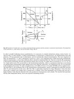
Whereas manganese bronzes experience hot shortness above 230 °C (450 °F), aluminum bronzes can be used at
temperatures as high as 400 °C (750 °F) for short periods of time without an appreciable loss in strength. For example, a
room-temperature tensile strength of 540 MPa (78 ksi) declines to 529 MPa (76.7 ksi) at 260 °C (500 °F), 460 MPa (67
ksi) at 400 °C (750 °F), and 400 MPa (58 ksi) at 540 °C (1000 °F). Corresponding elongation values change from 28% to
32, 35, and 25%, respectively.
Unlike manganese bronzes, many aluminum bronzes increase in yield strength and hardness but decrease in tensile
strength and elongation upon slow cooling in the mold. Whereas some manganese bronzes precipitate a relatively soft
phase during slow cooling, aluminum bronzes precipitate a hard constituent rather rapidly within the narrow temperature
range of 565 to 480 °C (1050 to 900 °F). Therefore, large castings, or smaller castings that are cooled slowly, will have
properties different from those of small castings cooled relatively rapidly. The same phenomenon occurs upon heat
treating the hardenable aluminum bronzes. Cooling slowly through the critical temperature range after quenching, or
tempering at temperatures within this range, will decrease elongation. An addition of 2 to 5% Ni greatly diminishes this
effect.
Nickel brasses, silicon brasses, and silicon bronzes, although generally high in strength than red metal alloys, are used
more for their corrosion resistance.
Cast beryllium coppers achieve variations in properties principally by varying heat treatment conditions. The "red"
beryllium copper alloys are exemplified by C82000 and C82200; the "gold" alloys include C82400, C82500, C82600, and
C82800. The casting alloys typically contain large amounts of beryllium than their wrought counterparts. The "gold"
casting alloys, in particular, have excellent casting characteristics and can be poured at relatively low temperatures into
molds with intricate shapes and fine detail.
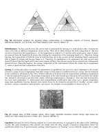
Figure 1 shows distributions of hardness and tensile-strength data for separately cast test bars of three different alloys.
Fig. 1 Distribution of hardness over 100 tests for t
hree copper casting alloys of different tensile strengths. (a)
C83600. Tensile strength, 235 to 260 MPa (34 to 38 ksi); 500 kg (1100 lbf) load. (b) C90300. Tensile strength,
275 to 325 MPa (40 to 47 ksi); 500 kg (1100 lbf) load. (c) C87500. Tensile strengt
h, 420 to 500 MPa (61 to 72
ksi); 1500 kg (3300 lbf) load
Properties of Test Bars. The mechanical properties of separately cast test bars often differ widely from those of
production castings poured at the same time, particularly when the thickness of the casting differs markedly from that of
the test bar.
The mechanical properties of tin bronzes are particularly affected by variations in casting section size. With increasing
section sizes up to 50 mm (2 in.), the mechanical properties both strength and elongation of the casting themselves
are progressively lower than the corresponding properties of separately cast test bars. Elongation is particularly affected;
for some tin bronzes, elongation of a 50 mm (2 in.) section may be as little as that of a 10 mm (0.4 in.) section or of a
separately cast test bar.
The metallurgical behavior of many copper alloy systems is complex. The cooling rate (a function of casting section size)
directly influences grain size, segregation, and interdendritic shrinkage; these factors, in turn, affect the mechanical
properties of the cast metal. Therefore, molding and casting techniques are based on metallurgical characteristics as well
as on casting shape.
Dimensional Tolerances
Typical dimensional tolerances are different for castings produced by different molding methods. A molding process
involving two or more mold parts requires greater tolerances for dimensions that cross the parting line than for
dimensions wholly within one mold part. For castings made in green sand molds, tolerances across the parting line
depend on the accuracy of pins and bushings that align the cope with the drag.
Figure 2 shows variations in two important dimensions for 50 production castings of red brass. The larger dimension
presented the greatest difficulty; none of the 50 production castings had an actual dimension as large as the nominal
design value. Figure 3 shows dimensional variations in two similar cored valve castings. For each design, both the cores
and the corresponding cavities in the castings were measured for approximately 100 castings. For both designs, the
castings had actual dimensions less than those of the cores. This indicates that cores may need to have a slightly larger
nominal size than is desired in the finished casting in order to ensure proper as-cast hole sizes.
Fig. 2 Variations from design dimensions for a typical red brass casting. Parts were cast in
green sand molds
made using the same pattern. All dimensions are given in inches.
Fig. 3 Variations from design dimensions fo
r two typical cast red brass valve bodies. Valve bodies, similar in
design but of different sizes, were made using dry sand cores to shape the internal cavities. The upper
histograms indicate dimensional variations for the castings; the lower histograms in
dicate variations for the
corresponding cores. All dimensions are given in inches.
Machinability
Machinability ratings of copper casting alloys are similar to those of their wrought counterparts. The cast alloys can be
separated into three groups. Table 3 shows the relative machinability of alloys belonging to the three groups.
Table 3 Machinability ratings of several copper casting alloys
UNS No.
Common name Machinability
rating, %
(a)
Group 1: free-cutting alloys
C83600
Leaded red brass 90
C83800
Leaded red brass 90
C84400
Leaded semired brass 90
C84800
Leaded semired brass 90
C94300
High-lead tin bronze 90
C85200
Leaded yellow brass 80
C85400
Leaded yellow brass 80
C93700
High-lead tin bronze 80
C93800
High-lead tin bronze 80
C93200
High-lead tin bronze 70
C93500
High-lead tin bronze 70
C97300
Leaded nickel brass 70
Group 2: moderately machinable alloys
C86400
Leaded high-strength manganese bronze
60
C92200
Leaded tin bronze 60
C92300
Leaded tin bronze 60
C90300
Tin bronze 50
C90500
Tin bronze 50
C95600
Silicon-aluminum bronze 50
C95300
Aluminum bronze 35
C86500
High-strength manganese bronze 30
C82500
Beryllium copper 30
Group 3: hard-to-machine alloys
C86300
High-strength manganese bronze 20
C95200
9% aluminum bronze 20
C95400
11% aluminum bronze 20
C95500
Nickel-aluminum bronze 20
(a)
Expressed as a percentage of the machinability of C36000, free-cutting brass. The rating is based on relative speed for equivalent tool life. For
example, a material having a rating of 50 should be machined at about half the speed that would be used to make a similar cut in C36000.
The first group includes only those containing a single copper-rich phase plus lead. Whether present merely to improve
machinability or for some other purpose, lead facilitates chip breakage, thus allowing higher machining speeds with
decreased tool wear and improved surface finishes.
Alloys of the second group contain two or more phases. Generally, the secondary phases are harder or more brittle than
the matrix. Silicon bronzes, several aluminum bronzes, and the high-tin bronzes belong to this group. Hard and brittle
secondary phases act as internal chip breakers, resulting in short chips and easier machining. Manganese bronzes produce
a long spiral chip that is smooth on both sides and that does not break. Some aluminum bronzes, on the other hand,
produce a long spiral chip that is smooth on both sides and that does not break. Some aluminum bronzes, on the other
hand, produce a long spiral chip that is rough on the underside and that breaks, thus acting like a short chip. Some of the
alloys in the second group are classified as moderately machinable because tools wear more rapidly when these alloys are
machined, even though chip formation is entirely adequate.
The third group, the most difficult to machine, is composed mainly of the high-strength manganese bronzes and
aluminum bronzes that are high in iron or nickel content.
General Purpose Alloys
General-purpose copper casting alloys are often classified as either red or yellow alloys. Table 2 show general properties
of these alloys.
The leaded red and leaded semired brasses respond readily to ordinary foundry practice and are rated very high in
castability. Alloy C83600 is the best known of this group and usually is referred to by a common name 85-5-5-5 or
ounce metal. Alloy C83600 and the modification, C83800 (83-4-6-7), constitute the largest tonnage of copper-base
foundry alloys. They are used where moderate corrosion resistance, good machinability, moderate strength and ductility,
and good castability are required. C83800 has lower mechanical properties but better machinability and lower initial
metal cost than C83600.
Both C83600 and C83800 are used for plumbing goods, flanges, feed pumps, meter casings and parts, general household
and machinery hardware and fixtures, papermaking machinery, hydraulic and steam valves, valve disks and seats,
impellers, injectors, memorial markers, plaques, statuary, and similar products.
Alloys C84400 and C84800 are higher in lead and zinc and lower in copper and tin than C83600 and C83800. They are
lower in price, and they have lower tensile strengths and hardnesses. Their widest application is in the plumbing industry.
The leaded yellow brasses C85200 and C85700 are even lower in price and mechanical properties. Their main
applications are die castings for plumbing goods and accessories, low-pressure valves, air and gas fittings, general
hardware, and ornamental castings. In general, they are best suited for small parts; larger parts with thick sections should
be avoided. Aluminum (0.15 to 0.25%) is added to yellow brasses to increase fluidity and to give a smoother surface.
All of the red and yellow general-purpose alloys, when properly made and cleaned, can be plated with nickel or
chromium.
Alloys that do not contain lead, such as the tin bronzes C90500 (Navy G bronze) and C90300 (modified Navy G bronze),
are considerably more difficult to machine than leaded alloys. Alloys containing 10 to 12% Sn, 1 to 2% Ni, and 0.1 to
0.3% P are known as gear bronzes. Up to 1.5% Pb frequently is added to increase machinability. The addition of lead to
C90300 increases machinability, but a concurrent decrease in tin is needed to maintain elongation. The leaded tin bronzes
include C92200 (known as steam bronze, valve bronze, or Navy M bronze) and C92300 (commercial G bronze).
All of the tin bronzes are suitable wherever corrosion resistance, leak tightness, or greater strength is required at higher
operating temperatures than can be tolerated with leaded red or semired brasses. The limiting temperature for long-time
operation of C92200 is 290 °C (550 °F); for C90300, C90500, and C92300, it is 260 °C (500 °F) because of the
embrittlement caused by the precipitation of a high-tin phase. This reaction does not occur in tin bronze with tin contents
less than 8%. For elevated-temperature service in handling fluids and gases, Table UNF-23 of the ASME Boiler and
Pressure Vessel Code defines allowable working stresses for C92200 (leaded tin bronze, ASTM B 61) and C83600
(leaded red brass, ASTM B 62) at different temperatures (Table 4).
Table 4 Allowable working stresses for C92200 and C83600 castings
Working stress Temperature
ASTM B 61
(a)
ASTM B 62
(b)
°C
°F MPa ksi MPa ksi
38
100 47 6.8 41 6.0
65
150 47 6.8 41 6.0
93
200 47 6.8 40 5.8
120
250 47 6.8 38 5.5
150
300 45 6.5 34 5.0
175
350 41 6.0 31 4.5
205
400 38 5.5 24 3.5
230
450 34 5.0 24 3.5
260
500 28 4.0 24 3.5
290
550 23 3.3 24 3.5
Source: ASME Boiler and Pressure Vessel Code, Table UNF-23
(a)
A minimum tensile strength of 235 MPa (34 ksi) is
specified for C92200 in ASTM B 61.
(b)
A minimum tensile strength of 250 MPa (30 ksi) is
specified for C83600 in ASTM B 62.
Nickel frequently is added to tin bronzes to increase density and leak tightness. Alloys containing more than 3% Ni are
heat treatable, but they must contain less than 0.01% Pb for optimum properties; one example of such an alloy is C94700
(88Cu-5Sn-2Zn-5Ni).
Bearing and Wear Properties
Copper alloys have long been used for bearings because of their combination of moderate-to-high strength, corrosion
resistance, and self-lubrication properties. The choice of an alloy depends on the required corrosion resistance and fatigue
strength, the rigidity of the backing material, lubrication, the thickness of bearing material, load, the speed of rotation,
atmospheric conditions, and other factors. Copper alloys can be cast into plain bearings, cast on steel backs, cast on rolled
strip, make into sintered powder metallurgy shapes, or pressed and sintered onto a backing material.
Three groups of alloys are used for bearing and wear-resistant applications: phosphor bronzes (Cu-Sn); copper-tin-lead
(low-zinc) alloys; and manganese, aluminum, and silicon bronzes.
Phosphor bronzes (Cu-Sn-P or Cu-Sn-Pb-P alloys) have residual phosphorus ranging from a few hundredths of 1% (for
deoxidation and slight hardening) to a maximum of 1%, a level that imparts great hardness. Nickel often is added to refine
grain size and disperse the lead. Copper-tin bearings have high resistance to wear, high hardness, and moderately high
strength. Alloy C90700 is so widely used for gears that it is commonly called gear bronze.
Phosphor bronzes of higher tin content, such as C91100 and C91300, are used in bridge turntables, where loads are high
and rotational movement is slow. The maximum load permitted for C91100 (16% Sn) is 17 MPa (2500 psi); for C91300
(19% Sn) it is 24 MPa (3500 psi). These bronzes are high in phosphorus (1% max) to impart high hardness, and low in
zinc (0.25% max) to prevent seizing. They are very brittle, and because of this brittleness are sometimes replaced by
manganese bronzes or aluminum bronzes.
High-lead tin bronzes are used where a softer metal is required at slow-to-moderate speeds and at loads not exceeding 5.5
MPa (800 psi). Alloys of this type include C93200 and C93700. The former, also known as 83-7-7-3, is an excellent
general bearing alloy; it is especially well suited for applications where lubrication may be deficient. Alloy C93200 is
widely used in machine tools, electrical and railroad equipment, steel mill machinery, and automotive applications. Alloy
C93200 is produced by the continuous casting process and has replaced sand castings for mass-produced bearings of high
quality. Alloys C93800 (15% Pb) and C94300 (24% Pb) are used where high loads are encountered under conditions of
poor or nonexistent lubrication; under corrosive conditions, such as in mining equipment (pumps and car bearings); or in
dusty atmospheres, as in stone-crushing and cement plants. These alloys replace the tin bronzes or low-lead tin bronzes
where operating conditions are unsuitable for alloys containing little or no lead. They also are produced by the continuous
casting process.
High-strength manganese bronzes have high tensile strength, hardness, and resistance to shock. Large gears, bridge
turntables (slow motion and high compression), roller tracks for anti-aircraft guns, and recoil parts of cannons are typical
applications.
Aluminum bronzes with 8 to 9% Al are widely used for bushings and bearings in light-duty or high-speed machinery.
Aluminum bronzes containing 11% Al, either as-cast or heat treated, are suitable for heavy-duty service (such as valve
guides, rolling mill bearings, screw-down nuts, and slippers) and precision machinery. As aluminum content increases
above 11%, hardness increases and elongation decreases to low values. Such bronzes are well suited for guides and
aligning plates, where wear would be excessive. Aluminum bronzes that contain more than 13% Al exceed 300 HB in
hardness but are brittle. Such alloys are suitable for dies and other parts not subjected to impact loads.
Aluminum bronze generally has a considerably higher fatigue limit and freedom from galling than manganese bronze. On
the other hand, manganese bronze has great toughness for equivalent tensile strength and does not need to be heat treated.
Electrical and Thermal Conductivity
Electrical and thermal conductivity of any casting will invariably be lower than for wrought metal of the same
composition. Copper castings are used in the electrical industry for their current-carrying capacity, and they are used for
water-cooled parts of melting and refining furnaces because of their high thermal conductivity. However, for a copper
casting to be sound and have electrical or thermal conductivity of at least 85%, care must be taken in melting and casting.
The ordinary deoxidizers (silicon, tin, zinc, aluminum, and phosphorus) cannot be used because small residual amounts
lower electrical and thermal conductivity drastically. Calcium boride or lithium help to produce sound castings with high
conductivity.
Cast copper is soft and low in strength. Increased strength and hardness and good conductivity can be obtained with heat-
treated alloys containing silicon, cobalt, chromium, nickel, and beryllium in various combinations. These alloys, however,
are expensive and less readily available than the standardized alloys. Table 5 presents some of the properties of these
alloys after heat treatment.
Table 5 Composition and typical properties of heat-
treated copper casting alloys of high strength and
conductivity
Tensile
strength
Yield
strength
UNS No.
Nominal composition
MPa
ksi MPa
ksi
Elongation,
%
Hardness
Electrical
conductivity,
% IACS
C81400
99Cu-0.8Cr-0.06Be 365 53 250 36 11 69 HRB 70
C81500
99Cu-1Cr 350 51 275 40 17 105 HB 85
C81800
97Cu-1.5Co-1Ag-0.4Be 705 102
515 75 8 96 HRB 48
C82000
97Cu-2.5Co-0.5Be 660 96 515 75 6 96 HRB 48
C82200
98Cu-1.5Ni-0.5Be 655 95 515 75 7 96 HRB 48
C82500
97Cu-2Be-0.5Co-0.3Si 1105
160
1035
150
1 43 HRC 20
C82800
96.6Cu-2.6Be-0.5Co-0.3Si
1140
165
1070
155
1 46 HRC 18
Cost Considerations
During the design of a copper alloy casting, foundry personnel or the design engineer must choose a method of producing
internal cavities. There is no general rule for choosing between cored and coreless designs. A cost analysis will determine
which is the more economical method of producing the castings, although frequently the choice can be decided by
experience.
For example, costs were compared for producing a small (13 mm, or in.) valve disk both as a cored casting and as a
machined casting (internal cavities made without cores). The machined casting could be produced for about 78% of the
cost of making the identical casting using dry sand cores a savings of 22% in favor of machined casting. In a similar
instance, producing a larger (38 mm, or 1 in.) valve disk as a cored casting that required only a minimal amount of
machining saved more than 8% in overall cost compared to producing the same valve disk without cores. Thus, for two
closely related parts, a difference in manufacturing economy may exist when all cost factors are taken into account.
Copper Powder Metallurgy Products
Introduction
COPPER-BASE POWDER METALLURGY (P/M) products rank second after iron and steel productsin terms of volume.
According to the Metal Powder Industries Federation (MPIF), the estimated shipments of copper and copper-base alloy
powders in 1996 were 20,500 Mg (23,000 short tons) in North America. The shipments in Europe were estimated to be
14,000 Mg (15,600 short tons), while the shipments in Japan were estimated at 6,200 Mg (7,000 short tons).
The use of copper in the P/M industry dates back to the 1920s, when commercial porous bronze bearings were developed
independently in the research laboratories of General Motors Corp. and Bound-Brook Oilless Bearing Co. These self-
lubricating bearings still account for the major portion of P/M copper and copper alloy applications. Other important
applications for copper and copper-base P/M materials include friction materials, brushes, filters, structural parts,
electrical parts, additives to iron powders (alloying as well as infiltration), catalysts, paints, and pigments.
In general, physical and mechanical properties of near full (theoretical) density copper and copper alloy P/M structural
parts are comparable to cast and wrought copper-base materials of similar composition. However, P/M copper parts vary
in density from the low density typical of self-lubricating bearings or filters to the near full density of electrical parts. The
physical and mechanical properties depend greatly on the density as a percentage of theoretical density.
Powder Production and Properties
Copper Powders
Copper powders of 99+ % purity are commercially available. The four major methods of producing such copper powders
are:
• Atomization
• Oxide reduction
• Hydrometallurgy
• Electrolysis
Of the previous methods, atomization and oxide reduction are presently practiced on a large scale globally.
Hydrometallurgical and electrolytic copper powders have not been manufactured in the United States since the early
1980s, and will not be described further. Information on copper powders produced by hydrometallurgy or electrolysis can,
however, be found in Volume 7, Powder Metallurgy, of the ASM Handbook.
Table 1 shows a comparison of some of the typical fundamental powder characteristics of commercial copper powders
made by the four production processes. Each process produces a unique particle shape and surface area.
Table 1 Characteristics of commercial copper powders
Composition, % Type of powder
Copper Oxygen
Acid insolubles
Particle shape Surface area
Electrolytic
99.1-99.8
0.1-0.8 0.03 max Dendritic Medium to high
Oxide reduced
99.3-99.6
0.2-0.6 0.03-0.1 Irregular; porous Medium
Water atomized
99.3-99.7
0.1-0.3 0.01-0.03 Irregular to spherical; solid
Low
Hydrometallurgical
97-99.5 0.2-0.8 0.03-0.8 Irregular agglomerates Very high
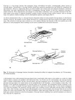
Atomization. In this process, molten copper flows through a refractory nozzle, and the liquid stream is disintegrated
into droplets by an impinging jet of water or gas. The droplets solidify into powder particles. The size and shape of these
particles are governed by the atomizing medium, pressure, and flow rate. Gas atomization produces spherical particles
while the shape of water-atomized powder particles can be controlled from almost spherical to irregular by controlling the
interaction between the water jet and the metal stream (Fig. 1). Higher pressures and lower flow rates favor finer powders;
average particle sizes less than 325 mesh (45 m) are feasible.
Fig. 1 Scanning electron micrographs of gas- and water-
atomized copper powders. (a) Nitrogen atomized. (b)
Water atomized, apparent density of 3.04 g/cm
3
. (c) Water atomized, apparent density of 4.60 g/cm
3
Water is the preferred atomizing medium for producing copper powder. The atomized powder is often subjected to an
elevated temperature reduction (to reduce any oxides formed during atomization) and agglomeration treatment to improve
the compacting properties. Table 2 shows the typical properties of commercial water-atomized copper powders.
Table 2 Properties of commercial grades of water-atomized copper powders
Chemical properties, % Physical properties
Tyler sieve analysis, %
Copper, %
Hydrogen
loss
Acid
insolubles
Hall flow
rate, s/50 g
Apparent density,
g/cm
3
+100
-100+150
-150+200
-200+325
-325
99.65
(a)
0.28 . . . . . . 2.65 Trace
0.31 8.1 28.2 63.4
99.61
(a)
0.24 . . . . . . 2.45 0.2 27.3 48.5 21.6 2.4
99.43
(a)
0.31 . . . . . . 2.70 Trace
0.9 3.2 14.2 81.7
>99.1
(b)
<0.35 <0.2 -50 2.4 <8 17-22 18-30 22-26 18-38
(a)
Water atomized plus reduced.
(b)
Contains magnesium
Oxide Reduction. This process involves oxidizing copper (particulate copper scrap, electrolytic copper, atomized
copper, etc.) and milling the oxide into powder. The oxide powder is reduced at elevated temperature by solid or gaseous
reducing agents, and the resulting sintered cake is milled into powder. The particle size is controlled through milling of
the starting oxide and the reduced sinter cake. The milled copper powder particles are irregular and porous (Fig. 2). A
broad range of pore characteristics can be obtained by controlling the reduction conditions.
Fig. 2 Oxide-reduced copper powder. 500×
The particle size, shape, and pore characteristics determine the compacting properties of the powder and the part
produced. Table 3 shows the typical properties of a commercial copper powder produced by the oxide-reduction process.
Table 3 Properties of commercial grades of copper powder produced by the oxide reduction process
Chemical properties, % Physical properties Compacted properties
Tyler sieve analysis, % Green strength, MPa (psi), at:
Copper
Tin
Graphite
Lubricant
Hydrogen
loss
Acid
insolubles
Apparent
density,
g/cm
3
Hall flow
rate, s/50
g
+100
+150
+200
+325
-325
Green
density,
g/cm
3
165 MPa (12
tsi)
6.30 g/cm
3
99.53
. . . . . . . . . 0.23 0.04 2.99 23 0.3 11.1 26.7 24.1 37.8
6.04 6.15 (890) . . .
99.64
. . . . . . . . . 0.24 0.03 2.78 24 . . . 0.6 8.7 34.1 56.6
5.95 7.85 (1140)
(a)
. . .
99.62
. . . . . . . . . 0.26 0.03 2.71 27 . . . 0.3 5.7 32.2 61.8
5.95 9.3 (1350)
(a)
. . .
99.36
. . . . . . . . . 0.39 0.12 1.56 . . . 0.1 1.0 4.9 12.8 81.2
5.79 21.4 (3100)
(a)
. . .
99.25
. . . . . . . . . 0.30 0.02 2.63 30 0.08 7.0 13.3 16.0 63.7
. . . . . . 8.3
(1200)
(a)
90
10 . . . 0.75 . . . . . . 3.23 30.6 0.0 1.4 9.0 32.6 57.0
6.32 . . . 3.80 (550)
88.5
10 0.5 0.80 . . . . . . 3.25 12
(b)
. . . . . . . . . . . . . . . . . . . . . 3.6 (525)
(a)
Measured with die wall lubricant only.
(b)
Carney flow
Copper Alloy Powders
Alloy powders are available in various compositions, including brasses, nickel silvers, tin bronzes, aluminum bronzes,
and beryllium bronzes. Alloy powders are produced by one of two methods:
• Preblending copper powders with other elemental powders such as tin, zinc, or nickel
• Prealloying during powder production
Preblending. Preblended powders are mixtures of selected compositions, with or without lubricant, that form the
desired alloy during sintering. The most common P/M copper alloy made with preblended powders is tin bronze used in
self-lubricating bearings. Typical bronze composition is 90Cu-10Sn, often containing up to 1.5% graphite. Some "dilute"
bronze bearings contain various amounts of iron replacing some of the copper and tin. Copper-lead and steel-backed
copper-lead-tin materials, used to replace solid bronze bearings, also use preblended powders because lead is virtually
insoluble in copper and cannot be prealloyed. Friction materials used in brakes and clutches contain disparate materials
such as copper with several other components including lead, tin, iron, graphite, molybdenum disulfide, oxides, etc. These
can only be made using preblended powders.
Prealloying. Prealloyed powders are generally produced by melting the constituents to form a homogeneous alloy and
atomizing the alloy melt by the methods similar to those used for the production of copper powder. They can also be
produced by sintering preblended powders and grinding the materials to attain the desired powder characteristics.
Brass and Nickel Silver. Air atomization is generally used for making prealloyed powders of brass and nickel silver
for use in high-density (>7.0 g/cm
3
) components. The low-surface tension of the molten alloys of these compositions
renders the particle shape sufficiently irregular to make the powders compactible (Fig. 3). Reduction of oxides is not
necessary for the standard P/M grades of brass and nickel-silver powders.
Fig. 3 Prealloyed air-atomized, nickel-silver powder (63Cu-18Ni-17Zn-2Pb). 165×
Commercial prealloyed brass and nickel-silver powders are available in leaded and nonleaded compositions. Commercial
brass alloys range from 90Cu-10Zn to 65Cu-35Zn. Leaded versions of 80Cu-20Zn and 70Cu-30Zn are most commonly
used for the manufacture of sintered structural parts that may require secondary machining operations. The only
commercially available nickel-silver powder has a nominal composition of 65Cu-18Ni-17Zn, which is modified by
addition of lead when improved machinability is required.
Bronze. Prealloyed bronze powders are not used widely for structural parts fabrication because their modular particle
form and high apparent density result in low green strength. However, blends of such powders with irregular copper
powders and phosphorus-copper yield sintered parts with good mechanical properties.
Table 4 shows typical properties of commercial grades of prealloyed brass, bronze, and nickel-silver powders.