Extractive Metallurgy of Copper 4th ed. W. Davenport et. al. (2002) Episode 3 potx
Bạn đang xem bản rút gọn của tài liệu. Xem và tải ngay bản đầy đủ của tài liệu tại đây (837.03 KB, 40 trang )
CHAPTER
4
Matte Smelting Fundamentals
4.1
Why
Smelting?
Beneficiation
of
copper ores produces concentrates consisting mostly
of
sulfide
minerals, with small amounts of gangue oxides
(AI2O3,
CaO, MgO, Si02).
Theoretically, this material could be directly reacted to produce metallic Cu by
oxidizing the sulfides to elemental copper and ferrous oxide:
CuFeS2
+
lo2
+
Cu"
+
FeO
+
2S02
FeS,
+
$0,
+
FeO
+
2S02
(4.1)
cu2s
+
0,
+
2CU"
+
so,
(4.2)
(4.3).
These reactions are exothermic, meaning that they generate heat.
As
a result, the
smelting of copper concentrate should generate (i) molten copper and (ii) molten
slag containing flux oxides, gangue oxides and FeO. However, under oxidizing
conditions,
Cu
tends to form Cu oxide as well as metal:
cu2s
+
40,
+
cu*o
+
so2
(4.4).
When this happens, the CuzO dissolves in the slag generated during
coppermaking. The large amount of iron in most copper concentrates means that
a large amount of slag would be generated. More slag means more lost Cu.
As
a
result, eliminating some of the iron from the concentrate before final
coppermaking is a good idea.
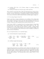
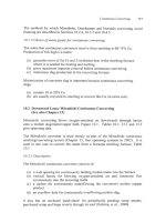
Fig. 4.1 illustrates what happens when a mixture of FeO, FeS and SiG2 is heated
to
1200°C.
The left edge
of
the diagram represents
a
solution consisting only
of
FeS and FeO.
In
silica-free melts with FeS concentrations above
-3
1
mass%, a
single oxysulfide liquid is formed. However, when silica is added, a liquid-state
57
58
Extractive Metallurgy
of
Copper
miscibility gap appears. This gap becomes larger as more silica is added.
Lines a,
b,
c
and d represent the equilibrium compositions
of
the two liquids.
The sulfide-rich melt is known as matte. The oxide-rich melt is known as slag.
Heating a sulfide concentrate to this temperature and oxidizing some
of
its Fe to
generate a molten matte and slag,
i.e.:
(4.5)
CuFeS2
+
O2
+
Si02
+
Cu-Fe-S
+
Fe0.Si02
+
SO2
matte
slag
1200°C
r
Solid Si02
\,
+
single liquid
\
,
'.
Solid Si02
+
two
liquids
A
Solid SiOl
+
single liquid
V
V
10
20
30 40
Mass%
Si02
Fig.
4.1.
Simplified partial phase diagram
for
the Fe-O-S-Si02 system showing liquid-
liquid (slag-matte) immiscibility caused by SiOz (Yazawa and Kameda,
1953).
The
heavy arrow shows that adding SiOz
to
an oxy-sulfide liquid causes it
to
split into FeS-
rich matte and FeS-lean slag. The compositions
of
points
A
and
B
(SOz
saturation) and
the behavior
of
Cu
are detailed in Table
4.1.
is known
as
matte
smelting.
It accomplishes the
partial
removal
of
Fe needed
to
make final coppermaking successfbl. Matte smelting is now performed on
nearly all Cu-Fe-S and
Cu-S
concentrates. This chapter introduces the
Matte Smelting Fundamentals
59
fundamentals of matte smelting and the influence of process variables.
Following chapters describe current smelting technology.
4.2
Matte and Slag
4.2.
I.
Slag
Slag is a solution of molten oxides. These oxides include FeO
from
Fe
oxidation, Si02 from flux and oxide impurities from concentrate. Oxides
commonly found in slags include ferrous oxide (FeO), ferric oxide (Fe2O3),
silica (SO2), alumina
(AI2O3),
calcia (CaO) and magnesia (MgO). As Fig.
4.1
shows, small amounts
of
sulfides can also be dissolved in FeO-Si02 slags.
Small amounts of calcia and alumina in slags decrease this sulfide solubility,
Table
4.
I.
The molecular structure of molten slag is described by dividing its oxides into
three groups
-
acidic, basic and neutral. The best-known acidic oxides are silica
and alumina. When these oxides melt, they polymerize, forming long polyions
such as those shown in Fig.
4.2.
These polyions give acidic slags high
viscosities, making them difficult
to
work with. Acidic slags also have low
solubilities for other acidic oxides. This can cause difficulty in coppermaking
because impurities which form acidic oxides (e.g., As2O3, Bi203, Sb203) won‘t
be removed in slag,
i.e.,
they will remain in matte
or
copper.
Adding basic oxides such as calcia and magnesia to acidic slags breaks the poly-
ions into smaller structural units. As a result, basic slags have low viscosities
Table
4.1,
Compositions
of
immiscible liquids in the Si02-saturated Fe-0-S
system,
1200°C
(Yazawa and Kameda,
1953).
Points
A
(slag) and
B
(matte) correspond
to
A
and
B
in
Fig.
4.1.
Added Cu2S (bottom data
set)
widens the miscibility gap. The
Cu2S reports almost entirely to the matte phase.
Composition (mass%)
~~ ~
System Phase
FeO FeS
SiOl
CaO
A1203
cu2S
FeS-FeO-SiO2
“A”
Slag
54.82 17.90 27.28
“B”
Matte 27.42 72.42
0.
I6
FeS-FeO-SiO:
+
CaO
Slag
46.72 8.84 37.80
6.64
Matte 28.46 69.39 2.15
FeS-FeO-Si02
+
A120i
Slag
50.05 7.66 36.35 5.94
CuzS-FeS-FeO-SiOz
Slag
57.73 7.59
33.83 0.85
Matte 27.54 72.15
0.31
Matte 14.92 54.69 0.25 30.14
60
Extractive Metallurgy
of
Copper
and high solubilities for acidic oxides. Up to a certain limit, adding basic oxides
also lowers the melting point of a slag. Coppennaking slags generally contain
small amounts of basic oxides.
Neutral oxides such as FeO and CuzO react less strongly with polyions in a
molten slag. Nevertheless, they have much the same effect. FeO and Cu20 have
low melting points,
so
they tend to lower a slag's melting point and viscosity.
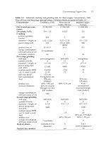
The slags produced in industrial matte smelting consist primarily of FeO, Fe203
and SO2, with small amounts
of
A1203, CaO and MgO, Table 4.2. Fig.
4.3
shows the composition limits for the
liquid
region in the Fe0-Fez03-SiO2
system at 1200°C and 1250°C.
Along the top line, the slag is saturated with
solid silica. Along the bottom boundary line, the slag is saturated with solid
FeO. The boundary at right marks the compositions at which dissolved FeO and
Fez03 react to form solid magnetite:
FeO
+
Fe203
+
Fe304(s)
(4.6).
Fig.
4.2.
Impact
of
basic oxides on the structure
of
silica polyions in moltcn
slags.
Adding basic oxides like CaO and
MgO
breaks
up
the polyions, reducing the melting
point
and
viscosity
of
the slag
0
=
Si;
0
=
0;
0
=
Cat+
or
Mg".
Table
4.2.
Compositions
of
industrial concentrates,
fluxes,
mattes, slags and dusts
for
various matte-smelting
processes,
200
1
Concentrate
Smelter& process Cu Fe
S
Si02
other
Caraiha
Outokumpu flash
Norddeutsche
Outokumpu flash
TOYO,
Outokumpu flash
Chino
lnco
flash
32 23 28
9
AI~O12
CaO
I
MgO
I
CaO
I
Zn
I
33 24 31
5
Al2OI<2
32 25 30
6
29
25 32 7
A1203
I
Caletones
32 25
30
6
A12O12
Teniente CaO
1
other
4
Port
Kemhla
Noranda
Sterlite, India
Isasmelt
Olympic Dam
OK
flash direct-
to-copper
Gresik
Mitsubishi
Onsan
Mitsuhishi
Onahama
Reverberatory
31 28
31
5
30
28
31 9
41
16
25 3
to
to
to
56
23 30
32
25
31 9
32 23 29 8
33 23 28 7
A1203
I
CaO
1
MgO
I
CaO
2
41*0,
1
AI203
2
CaO
0.5
A1201
2
CaO
0.4
AI2Oj
2
CaO
1
MgO
0.4
Flux
302
A120,
other
98
2
5-95
73
90
95
96
85
95
90
82
88
5
IO
4
2
1
I
3
4
A
CaO
2
4
Fe
2
cu
2
3
4
F~I
2
I
Fe
5
Fe
1.3
CaO
0.7
Matte
Cu Fe
S
0
62
12
22
65 12 22
1
63
IO
22
59
16
23
Fe104
74 4 20
other
4
I
72 6 20
63 13
99
0.8
0.4
68
8 22
69 8 22
44
26
26
Slag
Cu
Si02
total FejOI
S
A120,
other
1.8 31 42
16
0.5
MgO
2
Fe
1.5
32 39
1.3 33 37
0.8 34 43
6
27 38
to
8
2
30
46
0.7 29 44
20
15 30
to
to
to
24
20 40
0.7 33 39
09 34 38
0.7
32 37
5
0.6
4
13
0.6
5
413
16 2.7
4
15
0.8
2
3
0.7 4.9
CaO 3
MgO
1
CaO
1
MgO
2
CaO
1
other
3
CaO
3
CaO
3
0.1
3
CaOO.l
2 0.5
5
Ca06
3 0.4
5
Ca05
3
I
5
Ca04
Dust
Cu Fe
S
Si02
other
29 7 AI,O,Z
26 15 I2
20
15
9
30 17 12
34 6
II
34 23 23
33 32
36 14
63
9
19
17
5
9
13
13
5
CaO
1
3
A12012
CaO
I
7
7
Ca02
4
A1203
1
7
AllO,
2
10
3
so4
30
1
I
03
24
CaO3
62
Extractive Metallurgy
of
Copper
30
40
50
Mass%
FezOJ
Fig.
4.3.
Liquidus surface
in
the FeO-Fe203-Si02 system
at
1200°C and
1250°C
(Muan,
1955).
Copper smelting processes typically operate near magnetite saturation (line CD).
Extensive oxidation and lower smelting temperatures encourage the formation
of
Fez03 in the slag. Avoiding these conditions minimizes magnetite precipitation.
Along the left-hand boundary, the slag is saturated either with metallic iron or
solid fayalite (Fe2Si04). Under the oxidizing conditions of industrial copper
smelting, this never occurs. Table
4.2
lists the compositions
of
some smelter
slags, including their
Cu
content. Controlling the amount
of
Cu dissolved in
smelting slag is an important part
of
smelter strategy, Chapter
11.
Many measurements have been made of the viscosities of molten slags. These
have been used to develop a model which calculates viscosities as a function of
temperature and composition (Utigard and Warczok,
1995).
The model relies on
calculation of a viscosity ratio
(VR). VR
is the ratio of
A,
an equivalent mass%
in the slag
of
acidic oxides, to
B,
an equivalent mass%
of
basic oxides:
A
VR=-
B
(4.7)
A4atte
Smelting
Fundamentals
63
A=(%Si02)
+
1.5(%Cr20,)
+
1.2(%Zr02)
+
l.8(%A120,)
(4.8)
B
=
1.2(%FeO)
+
0.5(%Fe203
+
%PbO)
+
0.8(%Mg0)
+
0.7(%Ca0)
(4,9),
+2.3(%Na20
+
%K20)
+
0.7(%Cu20)
+
l.6(%CaF2)
Utigard and Warczok related
VR
to viscosity by regression analysis against their
existing database, obtaining:
-3660+12080JVR (4,10),
logp(kg/m.s)
=
-0.49-5.lE
+
T
(K)
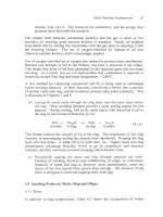
Fig.
4.4
shows thc effect
of
temperature and composition
on
the viscosity of FeO,
Fez03,
Si02
slags.
The specific gravity
of
smelting slags ranges between 3.3 and 3.7. It decreases
with increasing Fe203 and Si02 content (Utigard, 1994) and increases slightly
with increasing temperature.
Slag electrical conductivity is strongly temperature-dependent, ranging
at
smelting and converting temperatures between
5
and 20 ohm-lcm-' (Ziolek
and
Bogacz, 1987; Hejja
et
al.,
1994). It increases with Cu and iron oxide content
and with basicity.
1250
OC
1300
OC
0
10
20
30
40
Fez03
Fig.
4.4.
Effect of temperature
and
composition on
the
viscosity of FeO, Fez03,
SO2
slags,
g/m.s
(Vartiainen,
1998).
Viscosity is seen to increase with increasing
%
SiOz. For
viscosity in
kg/m.s,
divide by 1000.
The surface tension
of
smelting slags is 0.35-0.45 N/m (Nakamura
et
al.,
1988).
It decreases with increasing basicity, but is not strongly influenced by
temperature.
64
Extractive Metallurgy
of
Copper
4.2.2
Matte
As
Fig. 4.1 shows, immiscibility
of
matte and slag increases with increasing
silica content (Yazawa, 1956).
A
high sulfudiron ratio also increases the
completeness
of
separation as do calcia and alumina, Table 4.1.
There is some silica and oxygen solubility in matte, but Li and Rankin (1994)
demonstrated that increasing CuzS in matte decreases these solubilities
“dramatically”. As a result, the typical industrial matte contains only about one
percent oxygen, Table 4.2.
Mattes
do
not consist
of
polyions like those in slags. They appear instead
to
be
best represented as molten salts (Shimpo
et al.,
1986). Their specific gravity is
higher than that
of
slags and
so
they form the bottom layer in smelting furnaces.
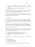
As Fig. 4.5 shows, their melting points are lower than the 1200°C of most slags,
Fig.
4.3.
OU
al
3
+
0
al
L
L
a
E
t-
I400
Liquid
I
I
cups
20
40
60
eo
Fe
;I.oB
Weight
%
FeS,.oe
Fig.
4.5.
Cu2S-FeS phase diagram (Schlegel and Schuller,
1952).
Actual matte melting
temperatures are
lower
than the liquidus line temperature due to impurities in the matte.
Their viscosities are low as well
-
-0.003
kg/m.s vs. 0.2-1 kg/m.s
for
typical
slags. Nevertheless, smelting furnaces are operated at about 125OoC,
to
ensure a
A4atte
Smelting Fundamentals
65
molten slag and superheated matte. This ensures that the matte and slag stay
molten during tapping and transfer.
The surface tension of Cu2S-FeS mattes ranges from 0.33-0.45 N/m, increasing
with
Cu2S
content. Temperature has little effect (Nakamura
et
al.,
1988;
Kucharski
et
al.,
1994).
Specific gravity ranges linearly from 3.9 for pure FeS to
5.2
for pure Cu2S.
It
decreases slightly with increasing temperature. Multiplying these specific
gravities by the kinematic viscosities measured by Nikiforov
et
al.
(1976), yields
viscosities of about 0.003 kg/m.s for pure Cu2S at 1250°C, falling to about
0.002
kg/m.s for mattes with
35
mass% FeS. The value then rises rapidly with
increasing FeS. It decreases slowly with increasing temperature.
Measurements of interfacial tension between molten mattes and slags were
reviewed by Nakamura and Toguri
(1
99
1).
Interfacial tension increases from
near zero in low-Cu mattes to about
0.20
N/m for high-Cu mattes
(-70
mass%
Cu*S).
Matte specific electrical conductances are
200
to
1000
ohm-' cm-' (Pound
et
al.,
1955, Liu
et
al.,
1980).
4.3
Reactions During Matte Smelting
The primary purpose of matte smelting is to turn the sulfide minerals in solid
copper concentrate into three products: molten matte, molten slag and offgas.
This is done by reacting them with
02.
The oxygen is almost always fed as
oxygen-enriched air. The initial reaction takes the form:
CuFeS2
+
O2
+
Cu-Fe-S
+
FeO
+
SO2
(4.1
I).
matte
The stoichiometry varies, depending on the levels of chalcopyrite and other
Cu-
Fe sulfide minerals in the concentrate and on the degree of oxidation of the Fe.
As
will be seen, smelting strategy involves a series of trade-offs. The most sig-
nificant is that between matte grade (mass%
Cu)
and recovery. Inputting
a
large
amount of
O2
will oxidize more
of
the Fe in the concentrate,
so
less Fe sulfide
ends up in the matte.
This generates a higher matte grade. On the other hand,
using too much oxygen encourages oxidation of
Cu,
as shown previously:
cu,s
+
+02
-+
cu20
+
so2
(4.4).
66
Extractive Metallurgy
of
Copper
The Cu oxide generated by this reaction dissolves in the slag, which is
undesirable.
As
a result, adding the correct amount
of
O2
needed to produce an
acceptable matte grade without generating a slag too high in Cu is a key part of
smelter strategy.
A
second set of reactions important in smelter operation involves the FeO
content of the slag. If the activity of FeO in the slag is too high, it will react with
Cu2S in the matte:
(4.12).
FeO
+
Cu2S
+
FeS
+
Cu20
in slag
in matte in matte
in
slag
This reaction is not thermodynamically favored (K,,-1O4 at 1200°C). However,
a high activity
of
FeO in the slag and a low activity
of
FeS in the matte generate
higher activities of CuzO in the slag. (This occurs if too much of the iron in the
concentrate is oxidized.) This again gives too much
Cu
in the slag.
In
addition,
FeO reacts with
02
to
form
solid magnetite if its activity is too high:
3Fe0
+
+02
-+
Fe304(s) (4.13).
As
a result, lowering the activity of FeO in the slag is important. It is done by
adding silica as a flux:
(4.14).
FeO
+
Si02
-+
Fe0.Si02
molten slag
However, again there is
a
trade-off. Flux costs money and the energy required to
heat and melt
it
also costs more as more silica is used. In addition, as Fig. 4.4
shows, the viscosities
of
smelting slags increase as the silica level rises. This
makes slag handling more difficult, and also reduces the rate at which matte
particles settle through the slag layer.
If
the matte particles can’t settle quickly
enough, they will remain entrained in the slag when it is tapped. This increases
Cu losses.
As
a result, the correct levels
of
FeO and Si02 in the slag require
another balancing act.
4.4 The
Smelting Process: General Considerations
While industrial matte smelting equipment and procedures vary, all smelting
processes have a common sequence
of
events. The sequence includes:
(a)
Contacting particles
of
concentrate andjlux
with
an Orcontaining gas in
a
hotfurnace.
This causes the sulfide minerals in the particles to rapidly
Matte Snielting Fundamentals
67
oxidize, Eqn. (4.11). The reactions are exothermic, and the energy they
generate heats and melts the products.
The contact time between concentrate particles and the gas is short
(a
few
seconds),
so
ensuring good reaction kinetics is essential.
Nearly all smelters
accomplish this by mixing the concentrate with the gas prior to injecting it into
the smelting furnace. The use of oxygen+nriched air instead of air also
improves reaction kinetics, and is increasingly popular.
Use of oxygen-enriched air or oxygen also makes the process more autothermal.
Because less nitrogen is fed to the furnace, less heat is removed in the offgas.
This means that more of the heat generated by the reactions goes into the matte
and slag.
As
a
result, lcss (or
no)
hydrocarbon fuel combustion is required
to
ensure the proper
final
slag and matte temperature, -1250°C.
A
new method for contacting concentrate and
O2
is being used in submerged
tuyere smelting furnaces. In these furnaces, concentrate is blown into
a
mixture
of molten matte and slag, and the oxidation process takes place indirectly. This
is discussed in Chapters
7
and
8.
(b)
Letting the matte settle through the dag luyer into the matte layer below
the slag.
Most smelting furnaces provide
a
quiet settling region for this
purpose. During settling, FeS in the matte reacts with dissolved
CuzO
in
the slag by the reverse of Reaction (4.12):
(4.15).
FeS
+
CuzO
+
FeO
+
Cu2S
in matte in slag in slag in matte
This further reduces the amount of
Cu
in the slag. The importance of low slag
viscosity in encouraging settling has already been mentioned. Keeping the slag
layer still
also
helps.
A
trade-off is at work here, too. Higher matte and slag
temperatures encourage Reaction (4.15) to go to completion and decrease
viscosity, but they cost more in terms of energy and refractory wear.
(c)
Periodically tapping the matte and slag through separate tap holes.
Feeding of smelting furnaces and withdrawing
of
offgas is continuous.
Removal of matte and slag is, however, done intermittently, when the
layers of the
two
liquids have grown deep enough. The location of tap
holes is designed to minimize tapping matte with slag.
4.5
Smelting Products: Matte, Slag and Offgas
4.5.
I
Matte
In addition
to
slag compositions, Table 4.2 shows the composition
of
mattes
68
Extractive Metallurgy
of
Copper
tapped from various smelters. The most important characteristic of a matte is its
grade (mass% Cu), which typically ranges between 45 and
75%
Cu (56-94%
Cu2S equivalent). At higher levels, the activity of CuzS in the matte rises rapidly,
and this pushes Reaction (4.12) to the right. Fig. 4.6 shows what happens as a
result.
The rapidly increasing concentration of Cu in slag when the matte grade rises
above 60% is a feature many smelter operators prefer to avoid. However,
producing higher-grade mattes increases heat generation, reducing fuel costs. It
also decreases the amount of
sulfur
to
be removed during subsequent converting
(decreasing converting requirements), and increases
SOz
concentration in the
offgas (decreasing gas-treatment costs). In addition, almost all copper producers
now recover
Cu
from smelting and converting slags, Chapter
11.
As a result,
production of higher-grade mattes has become more popular.
Most of the rest of the matte consists of iron sulfide (FeS). Table 4.3 shows the
distribution of other elements in copper concentrates between matte, slag and
offgas. Precious metals report almost entirely to the matte, as do most Ni, Se and
Te.
4.5.2
Slag
As Table 4.2 shows, the slag tapped from the furnace consists mostly of FeO and
SO2, with a small amount of ferric oxide. Small amounts of AI2O3, CaO and
MgO are also present, as is a small percentage of dissolved sulfur (typically less
than one percent). Cu contents range from less than
1
to as high as
7
percent.
Higher Cu levels are acceptable if facilities are available for recovering Cu from
smelter slag. Si02/Fe mass ratios are usually
0.7-0.8.
4.5.3 Offgas
The offgas from smelting contains
SOz
generated by the smelting reactions,
N2
from the air used for oxidizing the concentrate and small amounts of COz, H20
and volatilized impurity compounds. The strength of the offgas is usually 10 to
60 vol%
SOz.
The strength depends on the type of O2<ontaining gas used for
smelting, the amount of air allowed
to
leak into the furnace and the grade of
matte produced. Volume%
SO2
in smelter offgases has risen in recent years.
This is due to increased use of oxygen in smelting, which reduces the amounts of
nitrogen and hydrocarbon combustion gases passing through the furnace.
Smelter offgases may also contain substantial levels of dust (up to
0.3
kg/Nm3).
This dust comes from (i) small particles of unreacted concentrate or flux, (ii)
droplets of mattehlag that did not settle into the slag layer in the furnace and (iii)
volatilized elements in the concentrate such as arsenic, antimony, bismuth and
lead, which have either solidified as the gas cools or reacted to form non-volatile
compounds. The dust generally contains 2040 mass% Cu, making
it
potentially
Matte Smelting Fundamentals
69
25
20
5
0
0
20
40
60
80
100
Mass%
Cu
in
matte
Fig.
4.6.
%Cu in industrial smelting furnace slag (before slag cleaning) as
a
function of
%Cu
in
matte, 1999-2001. The increase in %Cu-in-slag above
60%
Cu-in-matte is
notable.
Table
4.3.
Estimated distribution of impurities during flash hrnace production of 55%
Cu matte (Steinhauser
et al.,
1984). Volatilized material
is
usually condensed and
returned to the furnace,
so
all impurities eventually leave the furnace in either matte
or
slag. Other industrial impurity distributions are shown in subsequent chapters.
Matte Slag Volatilized*
Copper 99
1
0
0
100
0
Alkaliialkaline-earth elements,
Aluminum, titanium
Ag,
Au,
Pt-group elements 99
1
0
Antimony
30
30
40
Arsenic
10
10
80
Bismuth
15
5 80
Cobalt 40 55 5
Lead
20
10
70
Nickel 50 45 5
Selenium 75 5
20
Zinc 15 45 40
*
Not
including
solid
dust
from
the
furnace.
70
Extractive Metallurgy
of
Copper
valuable. It is nearly always recycled to the smelting furnace, but it may be
treated hydrometallurgically to recover Cu and remove deleterious impurities
from the smelting circuit.
4.6
Summary
Matte smelting is the most common way of smelting Cu-Fe-S concentrates. It
entails heating, oxidizing (almost always with oxygen-enriched air) and fluxing
the concentrate at high temperatures,
1250°C.
The products are:
(a) molten Cu-Fe-S matte,
45-75%
Cu, which is sent to oxidation converting
to molten metallic copper, Chapters
9
and
10
(b)
molten Fe silicate slag, which
is
treated to recover Cu and then sold or
stockpiled, Chapter
11
(c) SOrbearing offgas, which is cooled, cleaned and sent to sulfwic
acidmaking.
Matte smelting oxidizes most, but not all, of the Fe and S in its input
concentrates. Total oxidation of Fe and
S
would produce molten Cu, but would
also result in large CuzO losses in slag, Chapter
12.
The expense of reducing this
CuzO and settling the resulting copper almost always overwhelms the advantage
of direct-to-copper smelting.
The next four chapters describe year
2002
industrial techniques for matte
smelting.
Suggested Reading
Mackey, P.J.
(1982)
The physical chemistry of copper smelting
slags
-
a
review.
Can.
Metall.
Q., 21,221 260.
Nakamura,
T.
and Toguri, J.M.
(1991)
Interfacial phenomena in copper smelting
processes.
In
Copper 91-Cobre 91 Proceedings
of
the Second International Conference,
Vol.
IV
Pyrometallurgy
of
Copper,
ed.
Diaz,
C., Landolt, C., Luraschi, A.A. and Newman,
C.J., Pergamon Press, New York, 537 55
I.
Utigard, T.A. and Warczok, A.
(1
995)
Density and viscosity of copperhickel sulphide
smelting and converting slags. In
Copper 95-Cobre 95 Proceedings
of
the Third
International Conference,
Vol.
lV
Pyrometallurgy
of
Copper,
ed. Chen, W.J., Dim, C.,
Luraschi, A. and Mackey, P.J., The Metallurgical Society of CIM, Montreal, Canada, 423
437.
References
Hejja, A.A., Eric, R.H. and Howat, D.D. (1994) Electrical conductivity, viscosity and
liquidus temperature of
slags
in electric smelting
of
copper-nickel concentrates. In
EPD
Congress 1994,
ed. Warren, G.W., TMS, Warrendale, PA, 621 640.
Matte Snielting Fundamentals
7
1
Kucharski, M., Ip, S.W. and Toguri, J.M. (1994) The surface tension and density of Cu2S,
FeS, Ni3S3 and their mixtures.
Can. Metall. Quart.,
33,
197 203.
Li,
H.
and Rankin, J.W. (1994) Thermodynamics and phase relations of the Fe-O-S-Si02
(sat) system at 1200°C and the effect of copper.
Met. Mater. Trans.
B,
25B,
79 89.
Liu,
C.,
Chang, M. and He, A. (1980) Specific conductance of CU~S, Ni3S, and
commercial matte.
Chinese Nonferrous Metals,
32( l), 76 78.
Muan, A.
(1955)
Phase equilibria in
the
system Fe0-Fe203-Si02.
Trans.
A.I.M.E.,
205,
965 976.
Nakamura, T., Noguchi,
F.,
Ueda, Y. and Nakajyo,
S.
(1988) Densities and surface
tensions
of
Cu-mattes and Cu-slags.
J. Min. Metall.
Inst.
Japan,
104,463
468.
Nakamura,
T.
and Toguri, J.M. (1991) Interfacial phenomena in copper smelting
processes. In
Copper 91-Cobre
91
Proceedings of the Second International Conference,
Vol. IVPyroinetallurgy of Copper,
ed. Diaz, C., Landolt, C., Luraschi, A.A. and Newman,
C.J., Pergamon Press, New York, NY, 537 551.
Nikiforov, L.V., Nagiev, V.A. and Grabchak, V.P. (1976) Viscosity of sulfide melts.
Inorg.
Muter.,
12,985 988.
Pound,
G.M.,
Derge,
G.
and Osuch,
G.
(1955) Electrical conductance in molten Cu-Fee
sulphide mattes.
Trans.
MME,
203,48
1
484.
Schlegel,
H.
and Schuller, A. (1952) Das Zustandsbild Kupfer-Eisen-Schwefel.
Zeitschrift
fur
Metallkunde,
43,42
I
428.
Shimpo, R.,
Goto,
S.,
Ogawa,
0.
and Asakura, I. (1986) A study on the equilibrium
between copper matte and slag.
Can.
Metall.
Quart., 25,
113
121.
Steinhauser,
J.,
Vartiainen, A. and Wuth, W. (1984) Volatilization and distribution
of
impurities in modem pyrometallurgical copper processing from complex concentrates.
JOM,
36(1),
54
61.
Utigard, T.A. (1994) Density of copperhickel sulphide smelting and converting slags.
Scand.
J.
Metall.,
23,
37
4
I.
Utigard, T.A. and Warczok, A. (1995) Density and viscosity of copperhickel sulphide
smelting and converting slags. In
Copper 95-Cobre
95
Proceedings of the lnternationul
Conference,
Vol.
IV
Pyrometallurgy of Copper,
ed. Chen,
W.J.,
Diaz, C., Luraschi, A. and
Mackcy,
P.J.,
Thc Metallurgical Society
of
CIM, Montreal, Canada,
423 437.
Vartiainen, A. (1998) Viscosity of iron-silicate slags at copper smelting conditions. In
Sulfide Smelting ‘98,
ed. Asteljoki, J.A. and Stephens,
R.L.,
TMS, Warrendale, PA,
363
371.
Yazawa,
A.
(1956) Copper smelting.
V. Mutual solution between matte and slag prod-
uced in the Cu,S-FeS-FeO-SiO2 system.
J. Mining
Inst.
Japun,
72,305
3
1
1.
72
Extractive Metallurgy
of
Copper
Yazawa,
A.
and Kameda,
A.
(1953)
Copper smelting.
I.
Partial liquidus diagram
for
FeS-FeO-Si02 system.
Technol.
Rep.
Tohoku Univ.,
16,40
58.
Ziolek,
B.
and Bogacz,
A.
(1987)
Electrical conductivity
of
liquid slags from the flash-
smelting of copper concentrates.
Arch. Metall.,
32,63
1
643.
CHAPTER
5
Flash Smelting -0utokumpu Process
(Written with David Jones, Kennecott Utah Copper, Magna, UT)
Flash smelting accounts for over
50%
of
Cu
matte smelting. It entails blowing
oxygen, air, dried Cu-Fe-S concentrate, silica flux and recycle materials into a
1250°C
hearth furnace. Once in the hot furnace, the sulfide mineral particles of
the concentrate (e.g. CuFeS2) react rapidly with the
O2
of the blast. This results
in (i) controlled oxidation of the concentrate’s Fe and
S,
(ii) a large evolution of
heat and (iii) melting of the solids.
The process is continuous. When extensive oxygen-enrichment of the blast is
practiced, it is nearly autothermal. It is perfectly matched to smelting the fine
particulate concentrates
(-100
pm) produced by froth flotation.
The products
of
flash smelting are:
(a) molten Cu-Fe-S matte,
-65%
Cu,
considerably richer in
Cu
than the input
concentrate, Table
4.2*
(b) molten iron-silicate slag containing
1
or
2%
Cu
(c) hot dust-laden offgas containing
30
to
70
volume%
SO2.
The goals of flash smelting are to produce:
(a) constant composition, constant temperature molten matte
for
feeding to
converters, Fig.
1.1
*
Two flash furnaces produce molten copper directly from concentrate, Chapter
12.
In
2002
this
is
economic
only
for
concentrates which give small quantities of slag. Another Outokumpu flash
furnace produces molten copper from solidified/ground
matte.
This
is
flash converting, Chapter
IO.
73
74
Extractive Metallurgy
of
Copper
(b) slag which, when treated for Cu recovery, contains only a tiny fraction of
the
Cu
input to the flash furnace
(c) offgas strong enough in
SO2
for its efficient capture as sulfuric acid.
There are two types of flash smelting
-
the Outokumpu process
(-30
furnaces in
operation) and the Inco process
(-5
furnaces in operation). The Outokumpu
process is described here, the Inco process in Chapter
6.
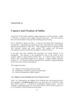
5.1
Outokumpu
Flash
Furnace
Fig. 5.1 shows a 2000-design Outokumpu flash furnace. It is
18
m long,
6
rn
wide and
2
m
high (all dimensions inside the refractories). It has a
4.5
m
diameter,
6
m high reaction shaft and a
5
m diameter,
8
m high offgas uptake. It
has one concentrate burner and smelts about
1000
tonnes of concentrate per day.
It has 5 matte tapholes and
4
slag tapholes.
Outokumpu flash furnaces vary considerably in size and shape, Table
5.1.
They
all, however, have the following five main features:
(a) concentrate burners (usually
1,
but up to
4)
which combine dry particulate
feed with 02-bearing blast and blow them downward into the furnace
(b) a reaction shaft where
most
of
the reaction between O2 and Cu-Fe-S feed
particles takes place
(c) a settler where molten matte and slag droplets collect and form separate
layers
(d) water-cooled copper block tapholes for removing molten matte and slag
(e) an uptake for removing hot SO2-bearing offgas.
5.1.1
Construction details
(Kojo
et
a/
2000)
The interior of an Outokumpu flash furnace consists
of
high-purity direct-
bonded magnesia-chrome bricks. The bricks are backed by water-cooled copper
cooling jackets
on
the walls and by sheet steel elsewhere. Reaction shaft and
uptake refractory is backed by water-cooled copper cooling jackets or by sheet
steel, cooled with water
on
thc outside.
The furnace rests
on
a 2-cm thick steel plate
on
steel-reinforced concrete pillars.
The bottom of the hrnace is air cooled by natural convection. Much of the
furnace structure is in operating condition after
8
years of use. Slag line bricks
may have eroded but the furnace can usually continue to operate without them.
This is because magnetite-rich slag deposits
on
cool regions of the furnace walls.
Flash
Smelting
-
Outokumpu
Process
75
Uptake
Reaction
Shaft
__
-
ro
SeEler
0
Fig. 5.1.
Side and end views of
a
year
2000
Outokumpu flash furnace. This furnace
was
designed to smelt
1000
tonnes of concentrate per day. Note the offset offgas
uptake.
A
concentrate burner is shown in Fig.
5.2.
It
sits atop the reaction shaft.
5.
I
.2
Cooling jackets
Recent design cooling jackets are solid copper with Cu-Ni (monel) alloy tube
imbedded inside (Jones
et
al.,
1999,
Kojo
et
al.,
2000).
The tube is bent into
many
turns
to maximize heat transfer
from
the solid copper
to
water flowing in
the monel tube. The hot face of the cooling jacket
is
cast in a waffle shape. This
provides a jagged face
for
refractory retention and magnetite-slag deposition
(Voermann
et al.,
1999;
Kojo,
et
al.,
2000;
Merry
et
al.,
2000).
Jackets are
typically
0.75
m
x
0.75
m
x
0.1
m thick with
0.03
m diameter,
0.004
m
wall
monel tube.
5.1.3
Concentrate burner
(Fig.
5.2)
Dry
concentrate and 02-rich blast are combined in the furnace reaction shaft by
blowing them through a concentrate burner. Dry
flux,
recycle dust and crushed
reverts are also added through the burner.
A
year 2000-concentrate burner consists of:
(a) an annulus through which 02-rich blast
is
blown into the reaction shaft
76
Extractive Metallurgy
of
Copper
Air
-7
Concentrate
/
Flux
Fig.
5.2.
Central jet distributor Outokumpu concentrate burner. The main goal of the
burner is to create a uniform concentrate-blast suspension
360'
around the burner. This
type
of
burner can smelt up to
200
tonnes of feed per hour. Its feed consists mainly
of
dry
(i) Cu-Fe-S concentrate,
-100
pm;
(ii) silica
flux,
-1
mm;
(iii) recycle dust; and (iv)
recycle crushed reverts*,
-1
mm.
(b) a central pipe through which concentrate falls into the reaction shaft
(c) a distributor cone at the burner tip, which blows air horizontally through
the descending solid feed.
Special attention
is
paid to uniform distribution of blast and solid feed
throughout the reaction shaft. It is achieved by introducing blast and solids
vertically and uniformly into quadrants around the burner (Baus,
1999)
and by
blowing the solids outwards with central jet distributor air.
*
Reverts are matte and slag inadvertently frozen during transport around the smelter. Examples are
matte and slag (i) frozen in ladles and (ii) spilled during tapping and pouring.
Flash
Smelting
-
Outokumpu
Process
77
5.1.4 Supplementary hydrocarbon fuel burners
All Outokumpu flash furnaces are equipped with hydrocarbon fuel burners atop
the reaction shaft and through the settler walls and roof. Shaft-top burners keep
the process in thermal balance. Settler burners eliminate cool zones
in
the
furnace. They are also used to adjust slag temperature.
5.1.5
Matte and slag tapholes
Matte and slag are tapped through single-hole water-cooled copper ‘chill blocks’
imbedded in the furnace walls. The holes are typically
60-80
mm diameter.
They are plugged with moist fireclay which is solidified
by
the heat of the
rumace
when the clay is pushed into the hole. They are opened by chipping
out
the clay and by melting it out with steel oxygen lances.
Matte is tapped via copper or refractory-lined steel launders into cast steel ladles
for transport to converting.
Slag is tapped down water-cooled copper launders into:
(a) an electric settling furnace for Cu settling and recovery
(b)
ladles for truck haulage to Cu recovery by slow
coolinglgrindingiflotation.
Both withdrawals are only partial. Reservoirs of matte and slag, -0.5 m deep
each are maintained in the furnace.
Tapping of matte is continuously rotated around its tapholes. This washes
out
solid buildups
on
the furnace floor by providing matte flow over the entire
hearth.
5.2
Peripheral Equipment
The Outokumpu flash furnace is surrounded by:
(a) concentrate blending equipment
(b) solids feed dryer
(c)
flash furnace feed bins and feed system
(d)
oxygen plant
(e) blast preheater (optional)
(f)
waste heat boiler
(8) dust recovery and recycle system
(h) gas cleaning system
(i) sulfuric acid plant
(j)
Cu-from-slag recovery system.
78
Extractive Metallurgy ofcopper
Table.
5.1.
Dimensions and production details
Smelter
Caraiba Metais S/A Norddeutsche Affinerie,
Dias d'Avila, Brazil Hamburg, Germany
Startup date
Size, inside brick,
m
hearth: w
x
1
x
h
reaction shaft
diameter
height above
settler
roof
gas uptake
diameter
height above roof
slag layer thickness
matte layer thickness
active slag tapholes
active matte tapholes
concentrate burners
Feed details tonneslday
new concentrate
(dry)
silica flux
oxygen
recycle flash furnace dust
converter dust
slag concentrate
reverts
other
temperature, "C
volume%
02
flowrate, thousand
Nm3/hr
Production details
matte, tonnedday
slag, tonnedday
mass% SiOz/mass% Cu
Cu recovery, flash slag
Cu
recovery, converter slag
offgas, thousand
Nm3/hour
vol.
?6
SO2,
leaving furnace
dust production, tonnedday
matte/slag/offgas temperature
hydrocarbon fuel burnt
hvdrocarbon fuel
Blast details
Fuel inputs, kg/hour
in reaction shaft
1982
6.8
x
24.3
x
2.9
5.5
6.1
5.1
10
0.4
0.4
2
5
1
2001 (32%
Cu)
71
to
150
120
6
0
60
200
60
40
1000 (62%
Cu)
950 (1.7%
Cu)
0.74
electric furnace
electric furnace
45
24
101-120
1230/13
1
O/135O0C
oil
400
+
natural
gas,
400
Nm3/hour
1972
6x20~3
6
7.5
4x8
10
0.7
0.2-0.5
2
4
1
2850 (33%
CU)
300-350
230
15
no
150
(ladle sculls, slimes,
various dusts
375
molten converter slag
ambient
40
50-60
1450 (65%
CU)
1600
(
1.5%
CU)
0.85
electric furnace
recycle to flash furnace
50-60
30-35
230
1210/122O/135O0C
no
in settler burners
oil,
600
oil,
1000;
no coke
6.8
x
20.1
x
2.2
6.2
5.9
3.1
6.3
0.3
0.8
2
6
1
3123 (34.8% Cu)
191
205
157
68
(converter
dust,
leach
plant
residue,
gypsum)
77
purchased scrap
ambient
27-33
69-75
1770 (65.5% CU)
1386
0.85
electric furnace
solidify1flotation
52-58
(calculated)
205
1258/1266/1266"C
29-35
1900-2
100
kg/hour
tine
coal with feed
1971
1979 1995
Flash
Smelting
-
Outokumpu
Process
79
of
six Outokumpu flash furnaces,
2001.
Nikko Mining Sumitomo Metal
LG
Nikko Kennecott Utah
Saganoseki, Japan Mining,
Toyo Japan Onsan, Korea
Copper,
U.S.A.
1973
none
none
670
bunker
C
oil occasionally
6.7
x
19.9
x
2.5
6
6.4
3
7
0.1
0.9
2
3
I
2190 (31.7% CU)
320
407
1 I4
15
70
40
solid matte
83
copper residue
450
48
34
1240 (63%
CU)
1212 (1.3%C~)
0.89
electric fce
with
coal
solidify1flotation
36.6
32.5
boiler
64,
esp
64
1233/1241/1370°C
348
oil,
100
pulverized coal
4.87
x
20
x
2.15
7.7
x
23.9
x
1.9
4
6.2
7
8.
I
3.6
8.4
0.4
0.5
2
4
1
5.0
11.9
0.4
0.5
5
4
1
1445 (31%
Cu)
122
286
(99yo
02)
104
14
0
22
2815 (27.1%cU)
207
206
40
70
47
sludges
&
residues
288 FC
slag
160
80
11.2
ambient
30.6
75-85
693 (62.5%
Cu)
0.7
609 (2%
CU)
1344 (71%
Cu)
2025
(1.8)
0.64
electric furnace
same
electric furnace
24
35
104
122011 30011 300°C
slag
flotation
recycle to smelting
41
45
boiler
125,
esp
63
12901 13301 1350°C
occasionally
bunker
C
oil,
84
kg/h
yearly avg
none
80
Extractive Metallurgy
of
Copper
(a) to (e) are described here.
(f)
to (i) are described in Chapter
14.
described in Chapter
1
1.
5.2.
I
Concentrate blending system
Most flash furnaces smelt several concentrates plus small amounts
of
miscellaneous materials, e.g. precipitate Cu. They also smelt recycle dusts,
sludges, slag flotation concentrate and reverts.
These materials are blended to give constant composition feed to the flash
furnace. Constant composition feed is the surest way to ensure (i) smooth flash
furnace operation and (ii) continuous attainment of target compositions and
temperatures.
(i)
is
Two techniques are used:
(a) bin-onto-belt blending by which individual feed materials are dropped
from holding bins at controlled rates onto a moving conveyor belt
(b) bedding, where layers
of
individual feed materials are placed on long
(occasionally circular [MVT,
20021)
A
shaped piles, then reclaimed as
vertical slices of blend.
The blended feed is sent to a dryer. Flux may be included in the blending or
added just before the dryer.
5.2.2
Solids feed dryer
Flash smelting's concentrate and flux are always dried to ensure even flow
through the concentrate burner. Steam and rotary dryers are used (Sagedahl and
Broenlund, 1999; Partinen
et al.,
1999). The water contents of moist and dry
feed are typically
8
and 0.2 mass%
H20.
Rotary dryers evaporate water
by
passing hot gas from natural gas or
oil
combustion through the moist feed. The temperature of the drying gas
is
kept
below -500°C (by adding nitrogen, recycle combustion gas or air) to avoid
spontaneous oxidation
of
the concentrate.
Steam dryers rotate hot, steam-heated stainless steel coils through the moist feed
(Sagedahl and Broenlund, 1999). Steam drying has the advantages
of:
(a) efficient use
of
flash furnace waste heat boiler steam
(b) little
SOz,
dust and offgas evolution because hydrocarbon combustion isn't
used
(c) low risk of concentrate ignition because steam drying is done at a lower
temperature -200°C than combustion-gas drying -500°C.
Flash
Smelting
-
Outokumpu
Process
8
1
Steam drying
is
being adopted widely in new and existing Outokumpu flash
smelters (Sagedahl and Broenlund, 1999; Isaksson and Lehner,
2000).
5.2.3
Bin
and feed system
Dried feed is blown up from the dryer by a pneumatic lift system. It is caught in
acrylic bags and dropped into bins above the flash furnace reaction shaft. It is
fed from these bins onto drag or screw conveyors for delivery to the concentrate
burner.
Bin design is critical for controlled feeding of the flash furnace. Fine dry flash
furnace feed tends to ‘hang up’ on the bin walls
or
‘flood’ into the concentrate
burner. This is avoided by ‘mass flow’ bins (Marinelli and Carson, 1992) that
are steep enough and smooth enough to give even flow throughout the bin.
The rate at which feed enters the concentrate burner is measured by supporting
the feed bins on load cells. The rate of feeding is adjusted by varying the speed
of
the conveyers below the bins (Kopke, 1999, Suzuki
et al.,
1998).
Other recent innovations include:
(a) a revolving table feeder atop the concentrate burner (Suzuki
et al.,
1998)
(b)
disc feeders and air slide convcycrs (Goodwill
et al.,
1999, Jones
et
al.,
1999).
Both systems are designed to give constant rate feeding and low wear.
5.2.4
Oxygen plant
The principal oxygen plant in an Outokumpu flash smelter is usually
a
liquefaction/ distillation unit, 200-1000 tonnes oxygen per day. It delivers 90-98
mass%
O2
industrial oxygen gas
(2
atmospheres gage) to the flash furnace.
Some smelters also havc
a
molecular sieve oxygen plant (vacuum
or
pressure
swing absorption) to supplement their
liquefactioddistillation
oxygen.
Molecular sieve plants come in small
(-100
tonnes oxygedday) units. They are
suitable for incremental additions to a smelter’s main oxygen plant.
Oxygen-enriched blast is prepared by mixing industrial oxygen and air as they
flow to the concentrate burner. The c’rygen is added through a diffuser (holed
pipe) protruding into the air duct. The diffuser is located
-6
duct diameters
ahead of the concentrate burner to ensure good mixing.
The rates at which oxygen and air flow into the concentrate burner are important