Extractive Metallurgy of Copper 4th ed. W. Davenport et. al. (2002) Episode 9 ppt
Bạn đang xem bản rút gọn của tài liệu. Xem và tải ngay bản đầy đủ của tài liệu tại đây (809.66 KB, 40 trang )
Hydronzetallurgical Copper Extraction
297
solvent extraction and electrowinning plants are given in Chapters
18
and
19.
Zaldivar (heap leach) Hellenic Copper Morenci (mine for leach)
1995 1996 1987
145
000
14
chalcocite, bronchantite,
chrysocolla
1%
chalcocite disseminated,
others
on
fracture
surfaces
75
odoff
conveyor stacking
I200
90
8
8
Yes
HDPE
Yes
belt curing
80% <I2
mm
Yes
belt curing
concentrated
8
no
H2S04-fortified
raffinate
8
0.25
20.7
0.008
emitters
0.5
0.5
belt acid cure, leach with
raffinate for 30 days,
then leach with recycling
pregnant solution for 270
days
3.5
I
.2
20.7
on-pad piping
8000
5
chalcocite
0.6
0.15
78% of leachable
permanent
excavator stacking
250
30
6
42
no
HDPE 1.5
mm
ye5
50% <75
mm
no
H2S04-fortified
raffinate
4
0.5
22
0.0075
emitters
0.6
I8
months
1.8
1
23
ditches, pipes, ponds
366 000
1
chalcocite, chrysocolla
0.261
0.23% in covellite
principally fracture filling
53% of leachable
conveyor stacking
2137
144
7-9
yes
(10”
m’
airiminutelm’)
HDPE over clay
both
<12 mm (crushed),
300
mm
ROM
yes, for about 30% of material,
in rotating drum
200 kg/m’ H2S04 onto heap for 3 days
raffinate
12 mine for leach, other 4-5
0.3
32
0.006
both, principally emitters
0.9
mine for leach: crushed material fines are
agglomerated with strong acid in a
rotating drum, then stacked in
7
m
lifts;
leached for 90 days, rested for 30 days
then leached again for 30 days
2.6
3
32
(clay
+
HDPE)-lined ponds
-4800 520 19 051
298
fitraciive Metallurgy
of
Copper
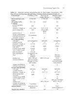
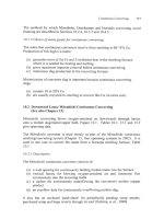
Table
17.3.
Details
of
heap leach aeration system at Quebrada Blanca (Salomon-de-
Friedberg,
1998,
1999,
2000).
Salomon-de-Friedberg
(1998)
gives detailed numerical
calculations. The air header pipe
is
placed on the uphill side of the heap base. Quebrada
Blanca has -20 of these heaps.
Item
Description
Individual heap (module)
85
m
x
400
m horizontal dimensions
(34
000
m2). Consists
of
7
m lifts, eventually piled to a total of
60
m high.
170
rn3/minute
(0.00s
m31midm2
of top
surface). The
design assumes 20% utilization
of
02
entering heap
0.45
m diameter HDPE pipe, corrugated outside for
strength, smooth inside
5
cm
HDPE pipes,
2
mm diameter hole every
1
m,
rotated
around the pipe. The pipes are spaced 2
m
apart.
Air supply rate
Air header
(400
m long)
Air distribution lines
(85m long)
Fan single stage axial fan,
-0.1
atmosphere gage delivery
uressure
17.2.5
Pregnant solution collection
The product pregnant solution (1 to
6
kg Cu++/m3) from heap leaching flows by
gravity down -10 cm polymer drain pipes on the sloping heap base to a
collection trench. The solution gets into the pipes through
2
mm wide,
20
mm
long slits in the polymer pipe. The pipes are spaced
2
to
4
m apart about
45"
across the slope.
The solution then flows by pipeline from the collection trench to a pond or tank.
It is sent from there by gravity or pumping to solvent extraction/ electrowinning
for copper metal production.
High density polyethylene pipes are used for low pressure flows.
316L
stainless
steel pipe is used for high pressure pumped flows.
I
7.2.6
Ore preparation
Preparation of ore for heap leaching varies from simple placement of run-of-
mine
(ROM)
ore on the leach heaps to:
(a)
placement of run-of-mine ore on the heap followed by trickling strong
H2S04-H20
solution through the heap ('acid curing')
(b) crushing
of
the ore followed by rotating-drum agglomeration with strong
sulfuric acid then placement of the agglomerate on the leach heap.
Placement of run-of-mine ore
is
the cheapest method.
However, it gives the
slowest and least efficient
CU"
recovery.
Hydiwmetallurgical Copper Extraction
299
'Acid curing' quickly dissolves CU++ from readily soluble 'oxide' minerals and it
acidifies the heap, thereby preventing ferric sulfate precipitation during
subsequent leaching. Typically,
10
or 20 kg of strong sulfuric acid per tonne of
ore are supplied to the heap over a period of
-10
days (shorter for 'oxide' ores
and longer for sulfide ores, Iasillo and Schlitt, 1999).
Most heap leach
operations find that a preliminary acid cure economically enhances Cu++
extraction rate and efficiency, Table 17.2.
17.2.7
Crushing, agglomeration and acid curing
Cu++ extraction rate and efficiency improve with decreasing ore piece size
(Iasillo and Schlitt, 1999; Brierley and Brierley, 1999b). This has led many heap
leach operators to crush their run-of-mine ore to 1 cm pieces. Crushing below
1
cm doesn't further improve
Cut+
extraction (Salomon-de-Friedberg, 1999) while
crushing below
0.5
cm adversely decreases heap permeability (Brierley and
Brierley, 1999b).
The crushed ore is agglomerated with strong sulfuric acid in revolving
3
m
diameter, 9 m long drums, sloped
-6".
This (i) agglomerates the fines created
during crushing and (ii) acid cures the ore. The agglomerated material is then
placed on the leach heaps.
Optimum agglomeration conditions are (Salomon-de-Friedberg,
2000):
-1
cm crush size
60
to 90 seconds agglomeration
-10
RPM
drum rotation speed
-9%
moisture
in
agglomerate
-5
kg (or less) H2SO4 per tonne of ore.
Close attention is also paid to avoiding too much clay in the agglomerate. More
than 20% clay in agglomerate severely decreases heap permeability (Salomon-
de-Friedberg,
2000).
The rapid and efficient extraction
of
Cu" obtained by crushlagglomerateiacid
cure leaching
is
leading to its wider use, in Chile (Dufresne,
2000)
and
elsewhere, Table 17.2.
17.3
Steady-State
Leaching
The lixiviant for industrial leaching is the Cu"-depleted solution ('raffinate')
returning from solvent extraction,
Fig.
17.1. Its composition
is
typically
0.4
kg
Cu and
-5
kg
H2S04/m3 of solution as it leaves the solvent extraction circuit.
Sulfuric acid
is
often added
(to
-10
kg
H2S04/m3) before the raffinate is recycled
300
Extractive Metallurgy
of
Copper
to the leach heap.
flowrate.
Water may also be added to maintain design lixiviant
The lixiviant is added via an equispaced network of polymer pipes and drop
emitters
or
sprinklers on top of the heap. Its addition rate
is
about
lo-*
m3 of
lixiviant per hour per m2 of heap surface. This low rate prevents pooling of
lixiviant on the heap surface (allowing free movement of air in the heap).
Sprinklers and drip emitters are used almost equally. Sprinklers (wobblers) have
the advantage that they distribute solution evenly over large areas. Drip emitters
require little maintenance and avoid excessive evaporation and cooling.
The lixiviant almost always enters the heap at ambient temperature. In cold
areas it may be heated to enhance
Cu++
extraction rate (Salomon-de-Friedberg,
2000).
17.3.
I
Optimum
[each
conditions
Optimum leach conditions are:
(a) uniform heaps of optimum agglomerate which maintain their permeability
throughout their life
(b) leach conditions which maximize bacterial activity
(-3O"C,
pH
-2,
5-10
kg H2S04/m3
of
lixiviant, no organics)
(c) uniform, lixiviant application m3kour/m2) on the heap surface
without pooling
(d) well-designed impervious heap base sloping
less
than
5%
with an efficient
pregnant leach solution collection system
(e) adequate heap temperature, provided in cold regions by heating raffinate,
insulating pipes and covering heaps with polymer mesh or sheet
(Salomon-de-Friedberg,
2000).
And
for
sulfide leaching:
(0
a controlled, uniform air supply,
blown in from perforated pipes beneath the heap.
m3 of air/min/m2
of
heap surface,
17.4
Leaching
of
Chalcopyrite Concentrates
Chalcopyrite is not leached under the mild oxidizing conditions of heap
leaching. It can, however, be leached under stronger oxidizing conditions. This
has led to extensive study into leaching of chalcopyrite
concentrates
as an
alternative to smelting, Table
17.4.
Industrial plants were built in the
1970's,
80's
and
90's.
None, however, remains in production.
Hydrometallurgical
Copper
Extraction
30
I
The potential advantages of chalcopyrite concentrate leaching over smelting are:
(a) avoidance of gaseous effluents, particularly
SO2
(Ferron, 1999)
(b) construction of small leach plants at mine sites rather than shipping
concentrate to large, distant smelters (King and Dreisinger, 1995)
(c) treatment of high-impurity concentrates (Dreisinger and Saito, 1999)
(d) lower costs.
The principal proposed processes have been:
(a) ammonia-air leach
(b) halide leach
(c) high and moderate pressure oxygen leach.
Their status is given in Table
17.4.
17.5
Other Leaching Processes
Minor
Cu
leaching processes are
in
situ
,
tailings and agitation leaching of oxide
concentrates and roaster calcines. They are discussed in Biswas and Davenport
(1980, 1994).
17.6
Future Developments
The main future developments in
Cu
hydrometallurgy are:
(a) continued growth of heap leaching for efficient recovery of
Cu
from
'oxide' and chalcocite ores
(b) continued improvement in heap leaching through optimization of
crushing, acid curing, agglomeration, heap construction, aeration, lixiviant
composition, lixiviant application rate, bacterial activity and temperature
(c) continued study of all aspects
of
chalcopyrite leaching.
17.7
Summary
Hydrometallurgical extraction accounts for about 2.5 million tonnes of metallic
copper per year (about 20%
of
total primary copper production). Virtually all
of
this is produced by heap leaching.
Heap leaching consists of trickling H2SO4-H10 lixiviant uniformly through flat-
surface heaps of crushed ore agglomerate
or
run-of-mine ore. 'Oxide' ores are
leached quickly by H2S04 without oxidation. Chalcocite (and to a much lesser
extent bornite and covelite) are oxidized and leached by H2SO4-H2O-O2-Fef+'
solutions.
302 Extractive Metallurgy
of
Copper
Table
17.4.
Description and status of chalcopyrite concentrate leach processes (McElroy
and Young, 1999).
Name
of
process
Description Status
Arbiter=monia-O2 agitation pressure leach, 100 tonnes copper per day
pressure leach solvent extraction, plant started in 1974 but
(Arbiter
&
McNulty, electrowinning closed in 1977 due to
1999) technical difficulties and high
Escondida Ammonia-air agitation leach
80
000
tonnes
of
copper per
ammonia-air leach year plant started in
1994
but
(Duyvesteyn and followed by solvent closed due to its
slow
rate of
Sabacky, 1993, extraction electrowinning copper production
1995; Arbiter and recovery of metallic copper
McNulty, 1999)
Halide leach Halide leach, electrowinning Industrial scale attained.
(Cymet, CLEAR, (Biswas and Davenport, Interest
seems to
have waned
Cuprex and Intec 1994; Moyes, 2002) due
to
impure products,
processes) environmental problems and
Oxygen sulfuric acid High (7 atmospheres) and development is continuing
pressure leach
costs
of
Cu2S
to
CuS
+
CU++
adverse economics
moderate
02
pressure leach
with sulfuric acid, raffinate,
electrolyte and various
additives (Anderson, 2000;
Collins
et
ai.,
2000;
Fleming
et
al.,
2000)
Economic rapid leaching
of
sulfide ores
is
made possible by indigenous bacteria
which speed up the leaching process a million-fold. Their activity is maximized
by
a
pH of
-2,
a
temperature
of
-NoC
and an adequate
O2
supply.
The product of heap leaching is pregnant solution containing
1
to
6
kg Cu++/m3.
It
is collected
on
a sloping impervious HDPE sheet base beneath the leach
heaps.
It
is
sent
to
solvent
extractiodelectrowinning
for copper production,
Chapters
18
and
19.
The Cu++-depleted 'raffinate' from solvent extraction is
recycled
to
leaching, usually fortified with
H2S04.
CU"
leach rate and recovery are maximized by optimizing crush size, acid
curing, agglomeration, heap permeability, lixiviant composition, aeration and
bacterial activity.
Most
Cu
minerals are amenable to heap leaching. A critical exception is
chalcopyrite (CuFeSz), which doesn't dissolve under heap leach conditions. It
can be leached under strongly oxidizing conditions, but not yet economically.
li'ydrometallurgical Copper Extraction
303
Suggested Reading
Jenkins, J., Davenport, W. G., Kennedy,
B.
and Robinson, T. (1999) Electrolytic copper
-
leach, solvent extraction and electrowinning world operating data. In
Copper 99-Cobre
99 Proceedings of the Fourth International Conference.
Vol. IV, Hydrometallurgy
of
Copper,
TMS, Warrendale, PA, 493 566.
Jergensen
11,
G.V. (1999)
Copper Leaching, Solvent Extraction and Electrowinning
Technology,
SME, Littleton, CO.
Young, S.K. (1999) A look at leach SX-EW with 2020 vision. In
Copper 99-Cobre 99
Proceedings of the Fourth International Conference, Vol. IV, Hydrometallurgy
of
Copper,
ed. Young, S.K., Dreisinger, D.B., Hackl, R.P. and Dixon, D.G., TMS,
Warrendale, PA,
61
1
619.
References
Anderson, C.G. (2000) The treatment
of
chalcopyrite concentrates with nitrogen species
catalyzed oxidative pressure leaching.
In
EPD Congress
2000,
ed. Taylor, P.R., TMS,
Warrendale, PA, 489 501.
Arbiter,
N.
and McNulty, T. (1999) Ammonia leaching
of
copper sulfide concentrates. In
Copper 99-Cobre 99 Proceedings
of
the Fourth International Conference, Vol. IV,
Hydrometallurgy
of
Copper,
ed. Young, S.K., Dreisinger, D.B., Hackl, R.P. and Dixon,
D.G., TMS, Warrendale, PA, 197 212.
Biswas, A.K. and Davenport, W.G. (1980)
Extractive Metallurgy
of
Copper
Zfld
Edition,
Pergamon Press, New York, NY.
Biswas, A.K. and Davenport, W.G. (1994)
Extractive Metallurgy
of
Copper
3rd
Edition,
Elsevier Science Press, New York, NY (Chapter 18).
Breitenbach, A.J. (1999) The good, the bad, and the ugly lessons learned in the design
and construction
of
heap leach pads.
In
Copper Leaching, Solvent Extraction and
Electrowinning Technology,
ed. Jergensen
11,
G.V., SME, Littleton, CO, 139 147.
Brierley, C.L. and Brierley, J.A. (199Ya) Copper bioleaching: state-of-the-art. In
Copper
99-Cobre 99 Proceedings
of
the Fourth International Conference,
Vol.
IV,
Hydrometallurgy
of
Copper,
ed. Young, S.K., Dreisinger, D.B., Hackl, R.P. and Dixon,
D.G., TMS, Warrendale, PA, 59 68.
Brierley, C.L. and Brierley, J.A. (1999b) Bioheap processes
~
operational requirements
and techniques. In
Copper Leaching, Solvent Extraction. and Electrowinning
Technology,
ed. Jergensen
11,
G.V., SME, Littleton, CO, 17 27.
Collins, M.J., Stiksma, J., Buban, K.R. and Masters, I.M. (2000) Pressure acid leaching
of
zinc and copper concentrate by Dynatec.
In
EPD Congress
2000,
ed. Taylor, P.R., TMS,
Warrendale, PA, 597 605.
304
Extractive Metallurgy
of
Copper
Columbus Instruments (2002) Oxymax-F measures 02/C02/CH4 consumption and
production www.colinst.com (Environmental Instruments, Respirometer for
Fermentation)
Dreisinger, D.B. and Saito, B.R. (1999) The total pressure oxidation of El Indio ore and
concentrate. In
Copper 99-Cobre 99 Proceedings of the Fourth International
Conference,
Vol.
IV,
Hydrometallurgy
of
Copper,
ed. Young,
S.K.,
Dreisinger, D.B.,
Hackl, R.P. and Dixon, D.G., TMS, Warrendale, PA, 181 195.
Dufresne, M.W.
(2000)
The Collahuasi copper project, Chile.
Mining, Metallurgy and Petroleum Bulletin,
93 (1039), 25 30.
Duyvesteyn, W.P.C. and Sabacky, B.J. (1993) The Escondida process for copper
concentrates. In
Extractive Metallurgy of Copper, Nickel and Cobalt (the Paul E.
Queneau International Symposium),
Vol.
I: Fundamental Aspects,
ed. Reddy, R.G. and
Weizenbach, R.N., TMS, Warrendale, PA, 881 910.
Duyvesteyn, W.P.C. and Sabacky, B.J. (1995) Ammonia leach process for Escondida
concentrates.
Transactions
of
the Institution
of
Mining and Metallurgv,
104,
C125
C140.
Ferron, C.J. (1999) New atmospheric leach process for copper sulphide ores and
concentrates. In
Copper 99-Cobre 99 Proceedings
of
the Fourth International
Conference,
Vol.
IV, Hydrometallurgy
of
Copper,
ed. Young,
S.K.,
Dreisinger, D.B.,
Hackl, R.P. and Dixon, D.G., TMS, Warrendale, PA, 15
1
165.
Fleming,
C.A.,
Ferron,
C.J.,
Dreisinger, D.B. and OKane, P.T. (2000) A process for the
simultaneous leaching and recovery of gold, platinum group metals and base metals from
ores and concentrates. In
EPD Congress
2000,
ed. Taylor,
P.R.,
TMS, Warrendale, PA,
419431.
Canadian Institute
of
Hiskey, J.B. (1993) Chalcopyrite semiconductor electrochemistry and dissolution. In
Extractive Metallurgy
of
Copper, Nickel and Cobalt (the Paul E. Queneau International
Symposium),
Vol.
I:
Fundamental Aspects,
ed. Reddy,
R.G.
and Weizenbach, R.N., TMS,
Warrendale, PA, 949 969.
Iasillo, E. and Schlitt, W.J. (1999) Practical aspects associated with evaluation of a copper
heap leach project. In
Copper Leaching, Solvent Extraction, and Electrowinning
Technology,
ed. Jergensen 11, G.V., SME, Littleton,
CO,
123 138.
Jenkins, J., Davenport, W.
G.,
Kennedy, B. and Robinson, T. (1999) Electrolytic copper
-
leach, solvent extraction and electrowinning world operating data. In
Copper 99-Cobre
99 Proceedings of the Fourth International Conference,
Vol.
IV, Hydrometallurgy
of
Copper,
TMS, Warrendale, PA, 493
566.
King, J.A. and Dreisinger, D.B. (1995) Autoclaving
of
copper concentrates. In
Copper
95-Cobre 95 Proceedings of the Third International Conference,
Vol.
Ill, Electrorefning
and Electrowinning of Copper,
ed. Dutrizac, J.E., Hein,
H.
and Ugarte, G., Metallurgical
Society of CIM, Montreal, Canada,
5
11 533.
McElroy, R. and Young, W. (1999) Pressure oxidation of complex copper ores and
concentrates. In
Copper Leaching, Solvent Extraction and Electrowinning Technology,
ed. Jergensen 11, G.V., SME, Littleton, CO, 29 40.
Hydrometallurgical Copper Extraction
305
Moyes,
J.A.
(2002) The Intec copper process (superior and sustainable copper
production). www.intec.com.au (Intec copper process)
Salomon-de-Friedberg,
H.
(1 998) Design aspects
of
aeration in heap leaching. Paper
presented at the Randol Cu Hydrometallurgical Roundtable '98, November 1998,
Vancouver, BC, Canada.
Salomon-de-Friedberg, H. (1999) Recent changes to operating practices at Minera
Quebrada Blanca. In
Copper 99-Cobre 99 Proceedings
of
the Fourth International
Conference,
Vol.
IV,
Hydrometallurgy
of
Copper,
ed. Young,
S.K.,
Dreisinger, D.B.,
IIackl,
R.P.
and Dixon, D.G., TMS, Warrendale,
PA,
3
12.
Salomon-de-Friedberg,
H.
(2000)
Quebrada Blanca: lessons learned in high altitude
leaching.
Paper presented
to
Instituto de Ingenieros de Minas de Chile, Expomin 2000,
Santiago, Chile, May
2000.
Weston, J.M., Dreisinger, D.B., Hackl, R.P. and King,
J.A.
(1995) Continuous biological
leaching
of
copper from a chalcocite ore and concentrate in a saline environment. In
Copper 95-Cobre 95 Proceedings
of
the Third International Conference,
Vol.
III,
Electrorefining and Electrowinning
of
Copper,
ed. Dutrizac,
J.E.,
Hein,
H.
and Ugarte,
G.,
Metallurgical Society of CIM, Montreal, Canada, 377 392.
CHAPTER
18
Solvent Extraction Transfer of Cu
from Leach Solution to Electrolyte
(Written with Jackson
Jenkins,
Phelps
Dodge,
Morenci,
AZ)
The pregnant leach solutions produced by most leaching operations are:
(a)
too
dilute in
Cu
(1-6
kg
Cu/m3)
and:
(b)
too impure
(1
-
10
kg Fe/m3)
for direct electrodeposition of high purity cathode copper.
Electrowinning from
these solutions would give soft, impure copper deposits.
Industrial electrowinning requires pure, Cu-rich electrolytes with
>35
kg Cu/m3.
This high concentration of
Cu:
(a) ensures that CU++ ions are always available for plating at the cathode
surface
(b) gives smooth, dense, high purity, readily marketable cathode copper.
Solvent e,xtraction provides the means for producing pure, high
Cu"
electrolytes
from dilute,
impure pregnant leach solutions.
It is a crucial step in the
production
of
-2.5
million tonnes
of
metallic copper per year. It continues to
grow in importance as more and more Cu ore is leached.
18.1
The Solvent Extraction Process
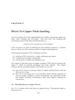
Copper solvent extraction (Fig. 18.1) entails:
307
308
Extractive Metallurgy
of
Copper
Mixer
EXTRACT
Raffinate
return
to
leach
f-
Settler
<
Settler
+
to
electrowinning
-1.5
kg Culm3
45
kg Culm3
STRIP
Loaded
organic
Mixer
Fig.
18.1.
Schematic plan view
of
copper solvent extraction circuit. The inputs are
pregnant leach solution and Cu-depleted electrolyte. The products are Cu-enriched
electrolyte and low-Cu raffinate. Fig.
18.3
shows
an
industrial mixer-settler. Fig.
18.4
shows the most common industrial circuit.
(a) contacting pregnant aqueous leach solution
(1-6
kg Cu++/m3,
0.5
to
5
kg
H2S04/m3) with a Cu-specific liquid organic extractant
-
causing
extraction
of
Cu++fyom the aqueous solution into the organic extractant
(raffinate) from the now-Cu-loaded organic extractant
(c) sending the low-Cu raffinate back to leach
(d) sending the Cu-loaded organic extractant to contact with strong-H2S04
electrowinning electrolyte
(170-200
kg H2SO4/m3)
-
causing
Cu
to be
stripped from the organic into the electrolyte
(e) separating by gravity the now-Cu-stripped organic extractant from the
now-Cu”-enriched aqueous electrolyte
(f)
returning the stripped organic extractant to renewed contact with pregnant
leach solution
(8) sending the Cu++-enriched electrolyte
to
electrowinning where its Cu* is
(b)
separating by gravity the now-Cu-depleted aqueous leach solution
electrodeposited as pure metallic ccpper.
The process is continuous. It typically takes place in ‘trains’ of
2
extraction
mixer-settlers
for
steps (a) and (b) and
1
strip mixer-settler for steps
(e)
and
(0.
An extraction system typically consists of
1
to
4
‘trains’ (Jenkins
et
a/.,
1999).
Solvent
Extraction Transfer of Copper
309
The organic extractants are aldoximes and ketoximes (Kordosky et al.,
1999).
They are dissolved
5
to
20
volume% in purijied kerosene.
18.2
Chemistry
The organic extractant removes Cu++ from pregnant leach solution by the
reaction:
2RH
+
Cu"
+
SO4
-+
R2Cu
+
2H+
+
SO4
(18.1)
organic aqueous pregnant
loaded raffinate
extractant leach solution
organic
(0.3
kg Cu/m3)
(1
to
6
kg Cu/m3
)
where
RH
is the aldoxime or ketoxime extractant.
Loading of organic extractant with
Cu
is seen to be favored by
a
low
concentration of sulfuric acid
(H')
in the aqueous phase.
So
contact of dilute
HzS04
aqueous pregnant leach solution with organic gives extraction
of
Cu
from
the aqueous phase into the organic phase.
After this organic loading step, the organic and aqueous phases are separated.
The Cu++-depleted raffinate is sent back to leach to pick up more Cut+. The
Cu-
loaded organic phase is sent forward to
a
'strip' mixer-settler where its Cu is
stripped into Cu*-depleted aqueous electrolyte.
The strip reaction is the reverse of Reaction
18.
I,
Le.:
2H'
+
SO4
+
R2Cu
+
2RH
+
Cu'+
+
SO4
(18.2).
high acid, Cu- loaded
depleted Cu-replenished
depleted electrolyte organic organic electrolyte
(-185
kg
H2S04/m',
extractant
extractant
(-165 kg
H2S04im3,
-35
kg
Cu/m')
-45
kg
Cuim')
It
is pushed to the right by the high sulfuric acid concentration of the aqueous
electrolyte. It strips Cu from the organic extractant and enriches the electrolyte
to its desired high-Cu++ concentration.
In summary, the organic extractant phase is:
(a)
loaded with
Cu
from weak
H2S04
pregnant leach solution
(b) separated from the pregnant leach solution
(c) contacted with strong
H2S04
electrolyte and stripped
of
its Cu.
It is the different
H2S04
strengths
of
pregnant leach solution and electrolyte
which make the process work.
3
10
Extractive Metallurgy
of
Copper
18.3
Extractants
The organic extractants used for
Cu
are oximes, Fig.
18.2.
Two classes are used:
aldoximes and ketoximes, Table
18.1.
They are dissolved in petroleum distillate
to produce an organic phase,
8
to
20
volume% extractant. This organic is
(i)
immiscible with
CuSO4-H2SO4-H*0
solutions and (ii) fluid enough (viscosity
=
0.01
to
0.02
kg/m.s) for continuous mixing, gravity separation and pumping
around the solvent extraction circuit.
A
successful Cu-extractant for any leach project must (Kordosky,
1992;
Kordosky
et
al.,
1999):
(a) efficiently extract Cu from the project’s pregnant leach solution
(b) efficiently strip Cu into the project’s electrowinning electrolyte
(c) have economically rapid extraction and strip kinetics
(d) disengage quickly and completely from leach solution and electrolyte,
i.e.
not
form
a stable emulsion
R
/bH/O
OH
R
I
A\
c
I/
Q
Fig.
18.2.
Oxime molecules and copper complex. The copper complex
is
formed from
two
oxime
molecules,
Eqn.
18.1.
Alodoximes:
R
=
C9HtY
or
C,ZH2S,
A
=
H.
Ketoxime:
R
=
CyH19,
A
=
CH3
(Dalton
et
al.,
1986;
Kordosky et al
1999).
Solvent Extraction Transfer
of
Copper
3
1
1
(e) be insoluble
in
the project’s aqueous solutions
(f)
be stable under extraction and strip conditions
so
that it can be recycled
many times
(g) not absorb sulfuric acid
(h) extract
Cu
preferentially over other metals in the pregnant leach solution,
particularly Fe and Mn
(i) not transfer deleterious species from pregnant leach solution to
electrolyte, particularly
C1
(i)
be soluble in an inexpensive petroleum distillate diluent
(k)
be nonflammable, nontoxic and non-carcinogenic.
Ketoxime and aldoxime extractants satisfy these requirements.
18.3.
I
Ketoximes
vs
aldoximes
Ketoximes have a methyl (CH3) group for
A
in Fig.
18.2.
Aldoximes have
hydrogen.
Ketoximes are relatively weak extractants with excellent physical properties,
Table
18.1.
Table
18.1.
Properties
of
Cu
solvent extraction extractants (Kordosky
et
ul.,
1999)
Aldoxime-ketoxime extractants are customized by adjusting their relative quantities.
Aldoxime-
Property Ketoxime Aldoxime with modifier ketoxime
mixtures, no
modifiers
Extractive strength
Stripping ability
CuiFe selectivity
Cu extraction and
stripping speed
Phase separation
speed
Stability
Crud generation**
Examples
moderate
very good
excellent
fast
very fast
very good
low
LIX
84-1
strong
good
excellent
very fast
very fast
very good*
variable
LIX
622
(tridecunol modified)
Acorga
M5640
(ester modified)
customized
customized
excellent
fast
very fast
very good
low
LIX
984N
~
*
Depends on modifier. **Depends on pregnant leach solution and modifier
3
12
Extractive
Metallurgy
of
Copper
Aldoximes are strong extractants. However, their Cu can only be stripped by
contact with
225+
kg H2S04/m3 electrolyte. This level of acid is too corrosive
for industrial electrowinning. It also tends to degrade the extractant.
For
these
reasons, aldoximes are only used when mixed with ketoximes or modifiers, e.g.
highly branched alcohols
or
esters.
The most common extractants in
2002
are ketoxime-aldoxime and ester-
modified aldoxime solutions.
18.3.2
Diluents
Undiluted ketoxime and aldoxime extractants are thick, viscous liquids. They
are totally unsuitable for pumping, mixing and phase separations. They are, for
this reason, dissolved
8
to
20
mass% in moderately refined high flash point
petroleum distillate (purified kerosene), hydrogenated to avoid reactive double
bonds (Bishop
et
a/.,
1999).
Commercial diluents typically contain -20 volume% alkyl aromatics,
-40%
naphthenes and
-40%
paraffins (Chevron Phillips,
2002).
18.3.3
Rejection
of
Fe
and
other
impurities
An efficient extractant must carry
Cu
forward from pregnant leach solution to
electrolyte while
not
forwarding impurities, particularly Fe, Mn and CI. This
is
a
critical aspect
of
efficient electrowinning of high purity copper. Fortunately,
ketoxime and aldoxime extractants have small solubilities for these impurities.
Ester-modified aldoximes are especially good in this respect (Cupertino
et
al.,
1999, Kordosky
et
al.,
1999).
Impurities may, however, be carried forward to electrolyte in droplets of
pregnant leach solution in the Cu-loaded organic. This carryover can be
minimized by (i) coalescing the pregnant solution droplets on polymer scrap; (ii)
filtering and (iii) washing the loaded organic (Jenkins
et
al.,
1999).
18.4
Industrial
Solvent
Extraction Plants
Solvent extraction plants are designed to match the rate at which
Cu
is leached in
the preceding leach operation. They vary in capacity from 20 to
600
tonnes of
Cu
per
day.
Table
18.2
gives operational details of five solvent extraction
plants. Additional details are given in Jenkins
et
a/.,
1999.
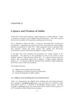
The key piece of equipment in
a
solvent extraction plant is the mixer-settler, Fig.
18.3
(Lightnin,
2002).
Mixer-settler operation consists
of
(a)
pumping aqueous and organic phases into a mixer at predetermined rates
Organic
overflow
Barren Settler
organic
extracta
u
-
enriched
Cu
-
depleted
aqueous
Pregnant leach
solution
Fig.
18.3.
Copper solvent extraction mixer-setter. The
two
mixing compartments, the large settler and the organic overflow/aqueous underflow
system are notable. Flow
is
distributed evenly
in
the settler by picket fences (not shown), Table
18.2.
3
14
Extractive Metallurgy
of
Copper
Table
18.2.
Details
of five
Cu
solvent extraction plants,
2001.
Details
of
the
Operation Cerro Colorado
El
Ahra
Startuo date
1994 1996
Cathode production, tonnesiyear
Total pregnant solution input rate, m'lhour
SX
plant detals
plant type
number of
SX
'trains'
extraction mixer-settlers per train
strip mixer-settlers per train
Mixer-settler details
Mixers
round or square
number of mixing compartments
compartment size: depth
x
width
x
length,
m
mixer system
construction materials
liquids residence time, minutes
length
x
width
x
depth, m
flow distributor system
construction materials
organic depth, m
aqueous depth, m
estimated residence time, minutes
estimated phase separation time, minutes
Organic details
extractant
volume% in organic diluent
diluent
organic washing?
aqueous removal from organic
crud removal system
crud treatment system
organic cleaning system
organic removal from raffinate
Settler
Flowrates per train, m31hour
pregnant solution input rate
organic flowrate, extraction to strip
depleted electrolyte input rate
%
of electrolyte flow sent to
SX
Solution details,
kg/m3
pregnant solution
raffinalc
barren organic
loaded organic
depleted electrolyte
enriched electrolyte
organic removal from electrolyte
electrolyte treatment before tankhouse
130
000
4000
series
5
2
1
square
3
Lightnin pump mixer
77030
316
stainless steel
3
22
x
22
xo.9
2
picket fences
HDPE-lined concrete
0.28-0.3
0.45
4
3
LIX
860-NIC/LIX 84-IC
13
Orfom
SX-12
no wash
none
pneumatic pump
Chuquicamata mechanical
breakage
clay treatment with
Sparkle filter
skimmer
750
1040
I80
18
cu
H2S04
4.8 5
0.4
II
3
5.6
37
180
52 159
none
garnevanthracite filtration
218 000
5000-7500
2
series
2
series-parallel
4
series
2;
series-parallel
3
series
2;
series-parallel
1
square
3
3.1
x
3.7
x
12.7
suction mixer
polymer concrete
2.4
28
x
29
x
1.1
2
picket fences
HDPE-lined concrete
0.27
0.63
3
PT5050-LIX 984NC
2
I
.4%Ll, 15.8%
L2
Conosol
170ES
water wash to pH
I.
I
Wemco coalescers
pneumatic pump
centrifuge and pressure
filter
zeolite treatment
Wemco coalescers
1400
series
2400
series-parallel
1500-l650
450-500
25
cu His04
4.94 6.44
0.70 12.10
3.33
7.40
36.33 171.41
40.29 170.9
Wemco pacesetter
coalescence
sand/garnet/anthracite
filtration
Solvent Extraction Transfer
of
Copper
3
15
equivalent leach and electrowinning plants are given in Chapters
17
and
19.
Zaldivar Hellenic Copper Morenci (Stargo)
1995 1996 1998
I45 000
4800
series
4
2
1
round
2
Outokumpu
VSF
mixers
Ti
&
3 16L
stainless steel
23.5
x
25
x
0.9
I
distributor,
1
picket fence
HDPE-lined concrete
0.25-0.3
15
LIX
984
NC
14.3
Orfom
SX
I2
one wash mixer-settler
8
Disep garneuanthracite filters
diaphragm pump
centrifugc
clay treatment
+
centrifuge
+
clay filter
floating absorption system
1200
I100
350
21
cu
H2SO4
3.8 0.55
0.28 6
3
7.2
41.5 165
5s
151
Cominco column flotation
Diseu sand/anthracite filters
8000
520
series-parallel
I
2
1
square
2
Davy impeller
3 16L
stainless steel
2
22x9~1
1
picket fence
3 16L
stainless steel
0.3
0.7
15
0.5
Acorga
M5640
8
Escaid
I
10
no wash
aqueous entrainment pumps
in loaded organic tank
2.5
cm diaphragm pump
bentonite mixing-recovery
filter press
pumping from pond
520
20
CU
H2S04
1.8
1
0.2 4
I
.3
3.8
30 180
38 160
sand/anthracite filters and heat
exchanging
I56
000
4320
series-parallel
I
3
I
round
3
5
diameter,
3.2
high
Outokumpu Spirok and
Dop pump mixers
stainless steel
3
24
x
26 x
1.25
3
picket fences
3 16L
stainless
steel
0.425
0.375
12
70
seconds
LIX 984
21
Conosol
170
I
wash stage mixer-settler
drain loaded organic tank
interface pumping and
settler dumping
clay mixing and
filter press
clay mixing and
filter press
skimmed from organic
recovery tanks
4320
2160
1250
65
cu
II2SO4
3.00 3.50
0.30
7.00
3.80
9.80
38.0 200.0
50.0 185.0
organic
IS
floated from rich
booster tank
6
anthracite garnet filters
3
16
Extractive Metallurgy
of
Copper
(b) mixing the aqueous and organic with impellers
(c) overflowing the mixture from the mixer through flow distributors into a
flat settler where the aqueous and organic phases separate by gravity
(organic and aqueous specific gravities,
0.85
and 1.1 respectively [Spence
and Soderstrom,
19991)
(d) overflowing the organic phase and underflowing the aqueous phase at the
far end of the settler.
Typical mixer-settler aqueous and organic flowrates are
500-4000
m3 per hour
(each).
The
mixer
is designed to create a well-mixed aqueous-organic dispersion.
Modem mixers consist of
two
or three mixing chambers. They create the
desired dispersion and smooth forward (plug) flow into the settler. Mixer
aqueous/organic contact times are
2
to
3
minutes
-
which brings the liquids close
to equilibrium. Entrainment of very fine droplets is avoided by using low tip-
speed
(<400
&minute) impellers (Spence and Soderstrom, 1999).
The
settler
is designed to separate the dispersion into separate aqueous and
organic layers. It:
(a) passes the dispersion through one or
two
flow distributors (picket fences
or screens)
to
give smooth, uniform forward
flow
(b) allows separate layers to
form
as the dispersion flows smoothly across the
large settler area.
The vertical position of the aqueous-organic interface is controlled by an
adjustable weir at the far end of the settler. It avoids accidentally overflowing
aqueous or underflowing organic.
Modem settlers are square in plan. This shape is the best for smooth flow and an
adequate residence time. Liquid residence times in the settlers are
10
to
20
minutes, Table
18.2.
This time is sufficient to guarantee complete phase
separation (laboratory separations occur in
0.5
to
2
minutes [Spence and
Soderstrom,
19991).
The aqueous phase is
-0.5
m
deep. The organic phase is
-0.3
m deep. Advance velocities are typically 1 to
5
m per minute.
18.4.1
‘Trains
2002
solvent extraction plants consist of one to four identical solvent extraction
circuits (‘trains’)
-
each capable of treating
500
to
4000
m3 of pregnant solution
per minute. Each train transfers
20-250
tonnes of
Cu
from pregnant solution to
electrolyte per day, depending on the Cu content and flowrate of the pregnant
solution.
Solvent Extraction Transfer
of
Copper
3
1
I
18.4.2
Circuit
design
Most copper solvent extraction is done in series circuits, Fig. 18.4. The
two
extraction mixer-settlers typically transfer -90% of Cu-in-pregnant-leach-
solution to the extractant (Jenkins
et
al.,
1999). The remaining Cu is not lost. It
merely circulates around the leach circuit.
The single strip mixer-settler strips
50%
to
65%
of the Cu-in-loaded-organic into
electrolyte. The remainder circulates around
the
solvent extraction circuit, Fig.
18.4. These transfer efficiencies can be increased by adding extraction and strip
mixer-settlers to the circuit. However, the
2
extraction,
1
strip mixer-settler
configuration predominates.
18.5
Quantitative Design
of
Series Circuit
This section describes the preliminary design of a series solvent extraction
circuit. It is based on the data in Table 18.3 and Fig. 18.4.
Table
18.3.
Preliminary specifications for design
of
solvent extraction circuit. They are
also given in Fig. 18.4.
Circuit type
Extractant
Specified organic/aqueous ratio in
extraction mixer-settlers
(NO)
Expected pregnant leach solution
composition and input rate
Specified composition of Cu
depleted electrolyte from
tankhouse
Specified composition of Cu-
enriched electrolyte returning to
tankhouse
Stripping data from laboratory
tests (Cognis, 1997)
series:
2
extraction mixer-settlers
expected extraction from pregnant solution into
organic: 90%
LIX
984N in Orfom
SX
12
diluent
Loads
-0.25
kg Cdm? per
volume%
LIX
984N
in organic (Cognis, 1997)
l/l
(m3 organic per hour/m3 aqueous per hour)*
1
strip mixer-settler
3
kg Cdm3,
1000
m3/hour
35
kg Cdm3 (sufficient to give high-purity
cathode copper at electrowinning cell exits)
45 kg Culm3
45 kg Cdm3 in enriched electrolyte is at
equilibrium with -1.5 kg Cdm3 in stripped
organic
~~
*O/A
ratios
of
-I
permit easy switching between aqueous-continuous and organic-continuous
operation.
Industrial
O/A
ratios
are
discussed
in
Biswas and Davenport
(1994).
3
18
Extractive Metallurgy
of
Copper
Intermediate Loaded
aqueous organic
*d
("l)
~
Mixer
dL
Extract
2
Extract
1
StriD
Settler
-
Mixer Settler
-
270 m3/hour
depleted electrolyte
from electrowinning
(35)
Fig.
18.4.
Plan view
of
series solvent extraction circuit. The bracketed numbers are
Cu
concentrations in
kg
Cu/m3. Industrial mixer-settlers are tight against each other
to
minimize plant area and flow distances. Note the two extraction mixer-settlers (Extract
1
and Extract
2)
and one strip mixer-settler. This is the most common arrangement (Jenkins
et
al.,
1999).
Flowrates and
Cu
concentrations are those in Table
18.3.
~lntermediate
18.5.1
Percent extractant
in
organic
organic
.p
(2.3)
LIX 984N extracts
up
to:
0.25
kg
Cu
per m3
of
organic phase per volume% LIX 984N in
the
organic
V
(Cognis,
1997). The LIX 984N strength which will extract
a
specified
amount
of
Cu
is calculated
by
the mass balance:
V
0.25
kg
of Cu
extracted
per
m3
of
organic per volume%
LIX
984 volumetric flowrate
volume%
LIX
984
in
in
the organic
of
organic, m3/hour
the organic
volumetric flowrate of
pregnant leach solution,
m
3ihour
required
Cu
extraction from
kg
Cu/m
=
pregnant leach solution into organic,
X
(1
8.3)
of
pregnant leach solution
or:
Solvent
Extraction
Transfer
of
Copper
3
19
required
Cu
extraction
from pregnant leach solution
0.25
volume%
LIX
984N
in
organic
=
X
AIO.
(where
A/O
is the aqueous/organic volumetric ratio entering the extraction
mixer-settler).
Extraction
of
Cu from a
3
kg Culm’ pregnant leach solution with the Table
18.3-
prescribed
NO
volume ratio
of
1/1
requires, therefore:
x
1
=
12%
3
volume%
LIX
984N
in organic
=
-
0.25
So
each train of the solvent extraction plant requires pumping of
1000
m3/hour
of
12
volume%
LIX 984N
in Orfom
SX
12
diluent.
This calculation is the first step in choosing the organic phase for a proposed
solvent extraction circuit. The chosen organic must then be tested with actual
leach and electrowinning solutions
to
ensure suitability for the proposed
operation.
18.5.2
Extraction eficiency
Under the dynamic conditions of two industrial mixer-settlers in series, Cu
extraction from pregnant leach solution is about
90%
(Jenkins et
al.,
1999).
In
the case of a
3
kg Cu/m’ pregnant solution, the raffinate leaving the series
of
two
extraction mixer-settlers will contain
-
0.3
kg Cu/m3 of raffinate, Fig.
18.4.
18.5.3
Rate of
Cu
extraction into organic
The overall rate at which Cu is extracted into the solvent extraction organic
phase is given by the equation:
Cu
in
pregnant
c
solution
leach solution
Cu
extraction rate
=
flow rate,
m hour
In this case it is:
cu extraction rate
=
]
(18.4).
raffinate
0.3
kg Cu/m3
of raftinate
1
=
2700
kg Cuhour.
320
Extractive
Metallurgy
of
Copper
This is also the overall rate at which metallic copper will have to be plated in the
electrowinning plant. It allows the electrowinning designer to calculate the
cathode area and current density for the proposed electrowinning plant.
18.5.4 Equilibrium strip
Cu
concentrations
The sulfuric acid concentration in depleted electrolyte is very high (-185 kg
H2S04/m3 of electrolyte). This causes copper to strip from the solvent extraction
organic into the electrolyte. Table 18.3 indicates that:
the 45 kg Culm3 electrolyte specified for return to the electrowinning tankhouse
will be at equilibrium with:
-1.5
kg Cu/m3 organic (12% LIX984Nin OYfom 12).
These concentrations are shown in Fig. 18.4. The precise equilibrium values
would need to be determined with the project‘s actual electrolyte.
18.5.5 Electrolyte flowrate
into
the strip mixer-settler
Section 18.5.3 indicates that the electrowinning plant must plate 2700 kg
metallic copper per hour. From the strip mixer-settler point of view, it means
that 2700 kg of Cu per hour must be transferred to electrolyte.
This, and the Table 18.3-specified depleted and enriched electrolyte
compositions (35 and 45 kg Cuirn’), permit calculation of the rate at which
electrolyte must flow into and out of the strip mixer-settler, i.e.:
electrowinning
kg Cu/hour
-
rate
-
extraction, m3/hour extraction, kg Cdm3 extraction, kg Cu/m3
1
electrolyte flowrate
Cu in electrolyte Cu in electrolyte
to and from solvent
x
leaving solvent
-
entering solvent
from which the electrolyte flowrate in and out of the strip mixer-setter is:
electrolyte flowrate
=
2700 kg Cdhour
=
270 m3 of electrolyte
(45
-
35) per hour
kg
Cu/m3
of electrolyte
Figure 18.4 summarizes flows and Cu concentrations in the newly designed
plant.
Solvent Extraction Transfer
of
Copper
32
1
Intermediate Loaded
aqueous organic
290
m3/hour
18.6
Stability
of
Operation
M:er
4
(’”)
Settler
(44)dl
Extract
2
Extract
1
StriD
Settler
t
Mixer Settler
-
Industrial solvent extraction circuits are easily controlled and forgiving.
Consider, for example, how the Section
18.5
circuit responds to an increase in
Cu concentration in pregnant leach solution (which would happen if easily-
leached ore is encountered in the mine).
Suppose that the pregnant solution
improves from the
3
kg Cu/m3 in Fig. 18.4 to
3.3
kg Cu/m3.
Copper extraction from the extra
0.3
kg Cu/m3 will probably be about
65%
instead of 90%
so
that:
depleted electrolyte
from
electrowinning
(35)
(a) the raffinate will contain 0.4 kg Cu/m3 rather than
0.3
kg Cu/m3
(b) 2900 kg of Cu will be transferred to organic in the extraction mixer-
settlers, Eqn. (18.4).
organic
(2.3)
The resulting flows and Cu concentrations are shown in Fig. 18.5.
V
Of
course, the rate at which copper is being plated will also have
to
be increased
to 2900 kg copper per hour.
This
can be done
by
increasing current density and
by bringing unused cells into operation.
V
Fig.
18.5.
Solvent extraction circuit that has been perturbed by receiving
3.3
kg Cu/m’
pregnant leach solution instead
of
3
kg
Cdm’
pregnant leach solution, Fig.
18.4.
It is
assumed that Cu electrowinning rate has been increased (by increasing current density) to
match the rate at which Cu is being transferred from pregnant leach solution to
electrolyte. Note that the only operating variable that has to be changed is electrolyte
recycle rate.