Volume 01 - Properties and Selection Irons, Steels, and High-Performance Alloys Episode 2 docx
Bạn đang xem bản rút gọn của tài liệu. Xem và tải ngay bản đầy đủ của tài liệu tại đây (4.9 MB, 200 trang )
M5003
(c)
517 75 345 50 187-241
3
M5503
(d)
517 75 379 55 187-241
3
M7002
(d)
621 90 483 70 229-269
2
M8501
(d)
724 105
586 85 269-302 1
(a)
Minimum in 50 mm (2 in.).
(b)
Annealed.
(c)
Air quenched and tempered.
(d)
Liquid quenched and tempered
The different microstructures of malleable irons are determined and controlled by variations in heat treatment
and/or composition. Table 3, for example, lists various types of malleable irons used in automotive applications
according to heat treatment and microstructure. The range of compositions for a ferritic or pearlitic
microstructure is given in Table 1.
Table 3 Grades of malleable iron specified according to hardness per ASTM A 602 and SAE J158
See Table 2 for mechanical properties.
Grade
Specified
hardness, HB
Heat treatment Microstructure
Typical applications
M
3210
156 max Annealed Ferritic
For low-stress parts requiring good machinability:
steering-gear housings, carriers, and mounting
brackets
M
4504
163-217 Air quenched and
tempered
Ferrite and tempered
pearlite
(a)
Compressor crankshafts and hubs
M
5003
187-241 Air quenched and
tempered
Ferrite and tempered
pearlite
(a)
For selective hardening: planet carriers, transmission
gears, and differential cases
M
5503
187-241 Liquid quenched
and tempered
Tempered martensite
For machinability and improved response to induction
hardening
M
7002
229-269 Liquid quenched
and tempered
Tempered martensite
For high-strength parts: connecting rods and universal-
joint yokes
M 269-302 Liquid quenched Tempered For high strength plus good wear resistance: certain
8501 and tempered martensite gears
(a)
May be all tempered martensite for some applications
Because the mechanical properties of malleable iron are dominated by matrix microstructure, the mechanical
properties may relate quite well to the relative hardness levels of different matrix microstructures.This general
effect of microstructure on malleable irons is similar to that of many other steels and irons. The softer ferritic
matrix provides maximum ductility with lower strength, while increasing the amount of pearlite increases
hardness and strength but decreases ductility. Martensite provides further increases in hardness and strength but
with additional decreases in ductility.
The mechanical properties of pearlitic and martensitic malleable irons are closely related to hardness, as
discussed in "Mechanical Properties" in the section "Pearlitic and Martensitic Malleable Irons" in this article.
Therefore, grades of malleable irons are dependably specified by hardness and microstructure in ASTM A 602
and SAE J158 (Table 3). Malleable irons are also classified according to microstructure and minimum tensile
properties (Table 4).
Table 4 Grades of malleable iron specified according to minimum tensile properties
See Table 2 for hardness.
Specification No. Class
or
grade
(a)
ASTM
metric
equivalent
class
(b)
Microstructure
Typical applications
Ferritic
32510 22010 ASTM A 47
(c)
, ANSI
G48.1, FED QQ-1-
666c
35018 24018
Temper carbon and ferrite
General engineering service at normal and
elevated temperatures for good machinability
and excellent shock resistance
ASTM A 338
(d)
. . . Temper carbon and ferrite
Flanges, pipe fittings, and valve parts for
railroad, marine, and other heavy-duty
service to 345 °C (650 °F)
ASTM A 197, ANSI
G49.1
(e)
. . . Free of primary graphite
Pipe fittings and valve parts for pressure
service
Pearlitic and martensitic
40010 280M10
45008 310M8
ASTM A 220
(c)
, ANSI
G48.2, MIL-I-11444B
45006 310M6
Temper carbon in necessary
matrix without primary
cementite or graphite
General engineering service at normal and
elevated temperatures. Dimensional tolerance
range for castings is stipulated.
50005 340M5
60004 410M4
70003 480M3
80002 560M2
90001 620M1
(a)
The first three digits of the grade designation indicate the minimum yield strength (× 100 psi), and the last two digits indicate minimum
elongation (%).
(b)
ASTM specifications designated by footnote (c) provide a metric equivalent class where the first three digits indicate minimum yield strength
in MPa.
(c)
Specifications with a suffix "M" utilize the metric equivalent class designation.
(d)
Zinc-coated malleable iron specified per ASTM A 47.
(e)
Cupola ferritic malleable iron
Table 2 summarizes some of the mechanical properties of the malleable irons listed in Tables 3 and 4.
Additional information on the properties and heat treatment of ferritic, pearlitic, and martensitic malleable irons
is provided in the following sections.
Ferritic Malleable Iron
The microstructure of ferritic malleable iron is shown in Fig. 2. A satisfactory structure consists of temper
carbon in a matrix of ferrite. There should be no flake graphite and essentially no combined carbon in ferritic
malleable iron. Because ferritic malleable iron consists of only ferrite and temper carbon, the properties of
ferritic malleable castings depend on the quantity, size, shape, and distribution of temper carbon and on the
composition of the ferrite.
Fig. 2 Structure of annealed ferritic malleable iron showing temper carbon in ferrite. 100×
Heat Treatment. Ferritic malleable iron requires a two-stage annealing cycle. The first stage converts primary
carbides to temper carbon, and the second stage converts the carbon dissolved in austenite at the first-stage
annealing temperature to temper carbon and ferrite.
After first-stage annealing, the castings are cooled as rapidly as practical to 740 to 760 °C (1360 to 1400 °F) in
preparation for second-stage annealing. The fast cooling step requires 1 to 6 h, depending on the equipment
used. Castings are then cooled slowly at a rate of about 3 to 10 °C (5 to 20 °F) per hour. During cooling, the
carbon dissolved in the austenite is converted to graphite and deposited on the existing particles of temper
carbon. This results in a fully ferritic matrix.
Composites. Fully annealed ferritic malleable iron castings contain 2.00 to 2.70% graphite carbon by weight,
which is equivalent to about 6 to 8% by volume. Because the graphite carbon contributes nothing to the
strength of the castings, those with the lesser amount of graphite are somewhat stronger and more ductile than
those containing the greater amount (assuming equal size and distribution of graphite particles). Elements such
as silicon and manganese in solid solution in the ferritic matrix contribute to the strength and reduce the
elongation of the ferrite. Therefore, by varying base metal composition, slightly different strength levels can be
obtained in a fully annealed ferritic product.
The mechanical properties that are most important for design purposes are tensile strength, yield strength,
modulus of elasticity, fatigue strength, and impact strength. Hardness can be considered an approximate
indicator that the ferritizing anneal was complete. The hardness of ferritic malleable iron almost always ranges
from 110 to 156 HB and is influenced by the total carbon and silicon contents.
The tensile properties of ferritic malleable iron are usually measured on unmachined test bars. These
properties are listed in Table 2.
The fatigue limit of unnotched ferritic malleable iron is about 50 or 60% of the tensile strength (see the two
unnotched plots in Fig. 3). Figure 3 also plots the fatigue properties with notched specimens. Notch radius
generally has little effect on fatigue strength, but fatigue strength decreases with increasing notch depth (Fig. 4).
Fig. 3 Fatigue properties of two ferritic malleable irons (25 mm, or 1 in., diam bars) from bending fatigue
tests
on notched and unnotched specimens. The unnotched fatigue limit is about 200 MPa (29 ksi) for the iron with a
342 MPa (50 ksi) tensile strength and about 185 MPa (27 ksi) for the iron with a 293 MPa (42.5 ksi) tensile
strength. Source: Ref 5
Fig. 4 Effects of notch radius and notch depth on the fatigue strength of ferritic malleable iron
The modulus of elasticity in tension is about 170 GPa (25 × 10
6
psi). The modulus in compression ranges
from 150 to 170 GPa (22 × 10
6
to 25 × 10
6
psi); in torsion, from 65 to 75 GPa (9.5 × 10
6
to 11 × 10
6
psi).
Fracture Toughness. Because brittle fractures are most likely to occur at high strain rates, at low
temperatures, and with a high restraint on metal deformation, notch tests such as the Charpy V-notch test are
conducted over a range of test temperatures to establish the toughness behavior and the temperature range of
transition from ductile to a brittle fracture. Figure 5 illustrates the behavior of ferritic malleable iron and several
types of pearlitic malleable iron in the Charpy V-notch test. This shows that ferritic malleable iron has a higher
upper shelf energy and a lower transition temperature to a brittle fracture than pearlitic malleable iron.
Additional information on the fracture toughness of malleable irons is available in the section "Pearlitic and
Martensitic Malleable Iron" in this article.
Fig. 5 Charpy V-notch transition curves for ferritic and pearlitic malleable irons. Source: Ref 1
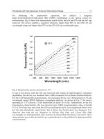
Elevated-Temperature Properties. Short-term, high-temperature tensile properties typically show no
significant change to 370 °C (700 °F). The short-term tensile properties of two ferritic malleable irons are
shown in Fig. 6. Sustained-load stress-rupture data from 425 to 650 °C (800 to 1200 °F) are given in Fig. 7.
Fig. 6 Short-term high-temperature tensile properties of two ferritic malleable irons.
(a) Tensile strength. (b)
Elongation. Source: Ref 5
Composition, %
Group
Grade
C Si Mn P S
Cr
A-1 35018 2.21
1.14
0.35
0.161
0.081
. . .
B-1 32510 2.50
1.32
0.43
0.024
0.159
0.029
E-1 35018 2.16
1.17
0.38
0.137
0.095
0.017
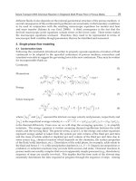
Fig. 7 Stress-
rupture plot for various grades of ferritic malleable iron. The solid lines are curves determined by
the method of least squares from the exis
ting data and are least squares fit to the data. The dashed lines define
the 90% symmetrical tolerance interval. The lower dashed curve defines time and load for 95% survivors, and
the upper dashed curve is the boundary for 5% survivors. Normal distribution is assumed. Source: Ref 6
The corrosion resistance of ferritic malleable iron is increased by the addition of copper, usually about 1%,
in certain applications, for example, conveyor buckets, bridge castings, pipe fittings, railroad switch stands, and
freight-car hardware. One important use for copper-bearing ferritic malleable iron is chain links. Ferritic
malleable iron can be galvanized to provide added protection. The effects of copper on the corrosion resistance
of ferrous alloys are documented in Corrosion, Volume 13 of ASM Handbook, formerly 9th Edition Metals
Handbook.
Welding and Brazing. Welding of ferritic malleable iron almost always produces brittle white iron in the weld
zone and the portion of the heat-affected zone immediately adjacent to the weld zone. During welding, temper
carbon is dissolved, and upon cooling it is reprecipitated as carbide rather than graphite. In some cases, welding
with a cast iron electrode may produce a brittle gray iron weld zone. The loss of ductility due to welding may
not be serious in some applications. However, welding is usually not recommended unless the castings are
subsequently annealed to convert the carbide to temper carbon and ferrite. Ferritic malleable iron can be fusion
welded to steel without subsequent annealing if a completely decarburized zone as deep as the normal heat-
affected zone is produced at the faying surface of the malleable iron part before welding. Silver brazing and tin-
lead soldering can be satisfactorily used.
Pearlitic and Martensitic Malleable Iron
Pearlitic and martensitic-pearlitic malleable irons can be produced with a wide variety of mechanical properties,
depending on heat treatment, alloying, and melting practices. The lower-strength pearlitic malleable irons are
often produced by air cooling the casting after the first-stage anneal, while the higher-strength (pearlitic-
martensitic) malleable irons are made by liquid quenching after the first-stage anneal. These two methods are
discussed in the sections "Heat Treatment for Pearlitic Malleable Irons" and "Heat Treatment for Pearlitic-
Martensitic Malleable Irons" in this article.
Given suitable heat treatment facilities, air cooling or liquid quenching after the first-stage anneal is generally
the most economical heat treatment for producing pearlitic or martensitic-pearlitic malleable irons, respectively.
Otherwise, ferritic iron produced from two-stage annealing is reheated to the austenite temperature and then
quenched. This method is discussed in the section "Rehardened-and-Tempered Malleable Iron" in this article.
Finally, the lower-strength pearlitic malleable irons can also be produced by alloying and a two-stage annealing
process. The last method involves alloying during the melting process so that the carbides dissolved in the
austenite do not decompose during cooling from the first-stage annealing temperature.
Heat Treatment for Pearlitic Malleable Irons. In the production of pearlitic malleable iron, the first-stage
anneal is identical to that used for ferritic malleable iron. After this, however, the process changes. Some
foundries then slowly cool the castings to about 870 °C (1600 °F). During cooling, the combined carbon
content of the austenite is reduced to about 0.75%, and the castings are then air cooled. Air cooling is
accelerated by an air blast to avoid the formation of ferrite envelopes around the temper carbon particles (bull's-
eye structure) and to produce a fine pearlitic matrix (Fig. 8). The castings are then tempered to specification, or
they are reheated to reaustenitize at about 870 °C (1600 °F), oil quenched, and tempered to specification. Large
foundries usually eliminate the reaustenitizing step and quench the castings in oil directly from the first-stage
annealing furnace after stabilizing the temperature at 845 to 870 °C (1550 to 1600 °F).
Fig. 8 Structure of air-
cooled pearlitic malleable iron. (a) Slowly air cooled. 400×. (b) Cooled in an air blast.
400×
The rate of cooling after first-stage annealing is important in the formation of a uniform pearlitic matrix in the
air-cooled casting, because slow rates permit partial decomposition of carbon in the immediate vicinity of the
temper carbon nodules, which results in the formation of films of ferrite around the temper carbon (bull's-eye
structure). When the extent of these films becomes excessive, a carbon gradient is developed in the matrix. Air
cooling is usually done at a rate not less than about 80 °C (150 °F) per minute.
Air-quenched malleable iron castings have hardnesses ranging from 269 to 321 HB, depending on casting size
and cooling rate. Such castings can be tempered immediately after air cooling to obtain pearlitic malleable iron
with a hardness of 241 HB or less.
Heat Treatment for Pearlitic-Martensitic Malleable Irons. High-strength malleable iron castings of
uniformly high quality are usually produced by liquid quenching and tempering. The most economical
procedure is direct quenching after first-stage annealing. In this procedure, the castings are cooled in the
furnace to the quenching temperature of 845 to 870 °C (1550 to 1600 °F) and held for 15 to 30 min to
homogenize the matrix. The castings are then quenched in agitated oil to develop a matrix microstructure of
martensite having a hardness of 415 to 601 HB. Finally, the castings are tempered at an appropriate temperature
between 590 and 725 °C (1100 and 1340 °F) to develop the specified mechanical properties. The final
microstructure consists of tempered martensite plus temper carbon, as shown in Fig. 9. In heavy sections,
higher-temperature transformation products such as fine pearlite are usually present.
Fig. 9 Structure of oil-quenched and tempered martensitic malleable iron.
(a) 163 HB. 500×. (b) 179 HB.
500×. (c) 207 HB. 500×. (d) 229 HB. 500×
Some foundries produce high-strength malleable iron by an alternative procedure in which the castings are
forced-air cooled after first-stage annealing, retaining about 0.75% C as pearlite. The castings are then reheated
at 840 to 870 °C (1545 to 1600 °F) for 15 to 30 min, followed by quenching and tempering as above for the
direct-quench process.
Rehardened-and-tempered malleable iron can also be produced from fully annealed ferritic malleable iron
with a slight variation in the heat treatment used for arrested-annealed (air-quenched) malleable. The matrix of
fully annealed ferritic malleable iron is essentially carbon free, but can be recarburized by heating at 840 to 870
°C (1545 to 1600 °F) for 1 h. In general, the combined carbon content of the matrix produced by this procedure
is slightly lower than that of arrested-annealed pearlitic malleable iron, and the final tempering temperatures
required for the development of specific hardnesses are lower. Rehardened malleable iron made from ferritic
malleable may not be capable of meeting certain specifications.
Tempering times of 2 h or more after either air cooling or liquid quenching are needed for uniformity. In
general, the control of final hardness of the castings is precise, with process limitations approximately the same
as those encountered in the heat treatment of medium- or high-carbon steels. This is particularly true when
specifications require hardnesses of 241 to 321 HB where control limits of ±0.2 mm Brinell diameter can be
maintained with ease. At lower hardnesses, a wider process control limit is required because of certain unique
characteristics of the pearlitic malleable iron microstructure.
The mechanical properties of pearlitic and martensitic malleable iron vary in a substantially linear
relationship with Brinell hardness (Fig. 10 and 11). In the low-hardness ranges, below about 207 HB, the
properties of air-quenched and tempered pearlitic malleable are essentially the same as those of oil-quenched
tempered martensitic malleable. This is because attaining the low hardnesses requires considerable coarsening
of the matrix carbides and partial second-stage graphitization. Either an air-quenched pearlitic structure or an
oil-quenched martensitic structure can be coarsened and decarburized to meet this hardness requirement.
Fig. 10 Relationships of tensile properties to Brinell h
ardness for pearlitic malleable irons from two foundries.
The mechanical properties of these irons vary in a substantially linear relationship with Brinell hardness, and in
the low-hardness ranges (below about 207 HB), the properties of air-quenched and te
mpered material are
essentially the same as those produced by oil quenching and tempering.
Fig. 11 Tensile properties of pear
litic malleable iron at various hardness levels. At foundry A, the iron was
made by alloying with manganese, with completion of first-
stage graphitization, air cooling under air blast from
938 °C (1720 °F), and subcritical tempering for spheroidizing.
At higher hardnesses, oil-quenched and tempered malleable iron has higher yield strength and elongation than
air-quenched and tempered malleable iron because of greater uniformity of matrix structure and finer
distribution of carbide particles. Oil-quenched quenched and tempered pearlitic malleable iron is produced
commercially to hardnesses as high as 321 HB, while the maximum hardness for high-production air-quenched
and tempered pearlitic malleable iron is about 255 HB. The lower maximum hardness is applied to the air-
quenched material because:
•
Hardness upon air quenching normally does not exceed 321 HB and may be as low as 269 HB;
therefore, attempts to temper to a hardness range above 255 HB produce nonuniform hardness and make
the process control limits excessive
•
Very little structural alteration occurs during the tempering heat treatment to a higher hardness, and the
resulting structure is more difficult to machine than an oil-
quenched and tempered structure at the same
hardness
• There is only a slight
improvement in other mechanical properties with increased hardness above 255
HB
Because of these considerations, applications for air-quenched and tempered pearlitic malleable iron are usually
those requiring moderate strength levels, while the higher-strength applications need the oil-quenched and
tempered material.
The tensile properties of pearlitic malleable irons are normally measured on machined test bars. These
properties are listed in Table 2.
The compressive strength of malleable irons is seldom determined, because failure in compression seldom
occurs. As a result of the decreased influence of the graphite nodules and the delayed onset of plastic
deformation in compression, compressive yield strengths are characteristically slightly higher than tensile yield
strengths for the same hardness (Ref 1, 7).
Shear and Torsional Strength. The shear strength of ferritic malleable irons is approximately 80% of the
tensile strength, and for pearlitic iron it ranges from 70 to 90% of the tensile strength (Ref 7). The ultimate
torsional strength of ferritic malleable irons is about 90% of the ultimate tensile strength. The yield strength in
torsion is 75 to 80% of the value in tension (Ref 1). Torsional strengths for pearlitic grades are approximately
equal to, or slightly less than, the tensile strength of the material. Yield strengths in torsion vary from 70 to 75%
of the tensile yield strength (Ref 7). The characteristic torsional properties of ferritic and pearlitic malleable
irons are related to hardness, as shown in Fig. 12. As expected, the amount of twist before failure decreases
with increasing strength.
Fig. 12 Torsional properties of pearlitic malleable irons in relation to hardness. Source: Ref 1
The modulus of elasticity in tension of pearlitic malleable iron is 176 to 193 GPa (25.5 × 10
6
to 28.0 × 10
6
psi). For automobile crankshafts, the modulus is important and must be determined with greater precision.
Fracture Toughness. The results of Charpy V-notch tests on pearlitic malleable iron are presented in Fig. 5.
The fracture toughness of ferritic and pearlitic malleable irons has not been widely studied, but one researcher
has estimated K
Ic
values for these materials by using a J-integral approach (Ref 8). Table 5 summarizes the
fracture toughness values obtained for the various grades of malleable iron at various temperatures. All of the
materials exhibited stable crack extension prior to fracture for 25 mm (1 in.) wide compact-tension specimens.
Table 5 Fracture toughness of malleable irons
Test temperature
Yield strength
K
Ic
Malleable iron grade
°C °F MPa ksi
MPa
m
ksi
in
Ferritic
24 75 230 33 44
40
M3210
-19 -3 240 35 42
38
-59 -74 250 36 44
40
Pearlitic
24 75 360 52 55
50
-19 -2 380 55 48
44
M4504 (normalized)
-57 -70 390 57 30
27
24 75 410 60 45
41
-19 -3 440 64 52
47
M5503 (quenched and tempered)
-58 -73 455 66 30
27
24 75 520 75 54
49
-19 -3 550 80 38
35
M7002 (quenched and tempered)
-58 -72 570 83 40 36
Source: Ref 7
As for ductile irons, fracture toughness testing indicates that malleable irons possess considerably more
toughness than is indicated by Charpy impact toughness results. Although the fracture toughness values for
pearlitic grades are similar to those obtained for ferritic grades, the higher yield strengths of the pearlitic grades
indicate that their critical flaw sizes, which are proportional to (K
Ic
/
y
)
2
, are less than those of the ferritic grades
of malleable iron. Detailed information on the principles of fracture toughness and the nomenclature associated
with fracture, mechanics studies is available in the Section "Fracture Mechanics" and the article "Dynamic
Fracture Testing" in Mechanical Testing, Volume 8 of ASM Handbook, formerly 9th Edition Metals Handbook.
Mechanical Properties at Elevated Temperatures. Figure 13 shows the short-term high-temperature tensile
strength of five pearlitic malleable irons and three martensitic malleable irons. Generally, the room-temperature
tensile strengths are related to hardness, while the tensile strengths at temperatures above about 450 °C (840 °F)
exhibit asymptotic behavior.
Fig. 13 Short-term elevated-
temperature tensile strengths of (a) partially spheroidized pearlitic malleable irons
produced by air cooling after the temper carbon anneal, (b) finely sp
heroidized pearlitic malleable irons
produced by oil quenching after the temper carbon anneal, and (c) oil-
quenched and tempered martensitic
malleable irons. The two martensitic malleable irons with hardnesses of 228 HB were reheated (reaustenitized)
after
the temper carbon anneal (18 h soak at 950 °C, or 1740 °F) and then oil quenched. The 263 HB iron was
oil quenched from 840 °C (1545 °F) after an anneal of 9.5 h at 950 °C (1740 °F). After oil quenching, all three
martensitic irons were tempered. Source: Ref 5
Figure 13 also illustrates two exceptions of the general relationship between hardness and room-temperature
tensile strength. The first exception is that the 230 HB pearlitic malleable iron in Fig. 13(a) has a slightly higher
room-temperature tensile strength than the 233 HB pearlitic malleable iron in Fig. 13(b). This difference,
however, diminishes at temperatures above 100 °C (210 °F).
The second exception is the difference in tensile strength for two malleable irons of the same hardness (Fig.
13c). This variation is perhaps attributable to the differences in heat treatment. Both of the martensitic
malleable irons with hardnesses of 228 HB were annealed, cooled, reheated (reaustenitized), and then oil
quenched. Before the reheat, however, the two irons underwent different cooling procedures. The 228 HB iron
with the higher strength was air cooled from 870 °C (1600 °F) after the temper carbon anneal (18 h soak at 950
°C, or 1740 °F), while the 228 HB martensitic iron with the lower strength was stabilized at 780 °C (1435 °F)
for 6 h and then slow cooled to 700 °C (1290 °F) before reheating.
Sustained-load stress-rupture data for eight grades of pearlitic malleable iron are shown in Fig. 14. Results of
high-temperature Charpy V-notch tests showing the effect of hardness on impact energy are given in Fig. 15.
Composition, %
Material
C Si Mn S P Cr
Others
Pearlitic (low carbon-high phosphorus)
Group E-2
2.27
1.15
0.89
0.098
0.135
0.019
. . .
Group G-2
2.29
1.01
0.75
0.086
0.11 . . .
. . .
Pearlitic (high carbon-low phosphorus)
Group C-2
2.65
1.35
0.41
0.15 . . . 0.018
0.0020 B
Group W-1
2.45
1.38
0.41
0.12 0.04 0.032
. . .
Alloyed pearlitic (low carbon-high phosphorus)
Group E-3
2.21
1.13
0.88
0.110
0.122
0.021
0.47Mo,1.03Cu
Group L-1
2.16
1.18
0.72
0.120
0.128
. . .
0.34Mo,0.83 Ni
Group L-2
2.16
1.18
0.80
0.123
0.128
. . .
0.40Mo,0.62 Ni
Group L-3
2.32
1.14
0.82
0.117
0.128
. . . 0.38Mo,0.65 Ni
Fig. 14 Stress-
rupture plot for pearlitic malleable iron (a) and alloyed pearlitic malleable iron (b). The solid
lines are curves determined by the method of least
squares from the existing data. The dashed lines define the
90% symmetrical tolerance interval. The lower dashed curve defines time and load for 95% survivors, and the
upper dashed curve is the boundary for 5% survivors. Normal distribution is assumed. Source: Ref 6
Fig. 15 Charpy V-notch impact energy of one heat of air-quenched and tempered pearlitic malleable iron
The unnotched fatigue limits of tempered pearlitic malleable irons (air cooled or oil quenched) are about 40
to 50% of tensile strength. Tempered martensitic malleable irons (oil quenched) have an unnotched fatigue limit
of about 35 to 40% of tensile strength (Fig. 16). The V-notched fatigue limits of the three irons in Fig. 16
ranged from 110 to 125 MPa (16 to 18 ksi) (Ref 5). Oil-quenched and tempered martensitic iron usually has a
higher fatigue ratio than pearlitic iron made by the arrested anneal method.
Fig. 16 Fatigue properties of three oil-quenched and tempered martensitic malleable irons from
bending fatigue
tests on unnotched 25 mm (1 in.) diam bars. Source: Ref 5
Wear Resistance. Because of its structure and hardness, pearlitic and martensitic malleable irons have
excellent wear resistance. In some moving parts where bushings are normally inserted at pivot points, heat-
treated malleable iron has proved to be so wear resistant that the bushings have been eliminated. One example
of this is the rocker arm for an overhead-valve automotive engine.
Welding and Brazing. Welding of pearlitic or martensitic malleable iron is difficult because the high
temperatures used can cause the formation of a brittle layer of graphite-free white iron. Pearlitic and martensitic
malleable iron can be successfully welded if the surface to be welded has been heavily decarburized.
Pearlitic or malleable iron can be brazed by various commercial processes. One application is the induction
silver brazing of a pearlitic malleable casting and a steel shaft to form a planetary output shaft for an
automotive transmission. In another automotive application, two steel shafts are induction copper brazed to a
pearlitic malleable iron shifter shaft plate.
Selective Surface Hardening. Pearlitic malleable iron can be surface hardened by either induction heating
and quenching or flame heating and quenching to develop high hardness at the heat-affected surface.
Considerable research has been done to determine the surface-hardening characteristics of pearlitic malleable
and its capability of developing high hardness over relatively narrow surface bands. In general, little difficulty
is encountered in obtaining hardnesses in the range of 55 to 60 HRC, with the depth of penetration being
controlled by the rate of heating and the surface temperature of the part being hardened (Fig. 17).
Fig. 17 Hardness versus depth for surface-
hardened pearlitic malleable irons. Curves labeled "Matrix" show
hard
ness of the matrix, converted from microhardness tests. O, oil quenched and tempered to 207 HB before
surface hardening; A, air cooled and tempered to 207 HB before surface hardening
The maximum hardness obtainable in the matrix of a properly hardened pearlitic malleable part is 67 HRC.
However, conventional hardness measurements made on castings show less than 67 HRC because of the
presence of the graphite particles, which are averaged into the hardness. Generally, a casting with a matrix
microhardness of 67 HRC will have about 62 HRC average hardness, as measured with the standard Rockwell
tester. Similarly, a Rockwell or Brinell hardness test on softer structures will show less than matrix
microhardness because of the presence of graphite.
Two examples of automobile production parts hardened by induction heating are rocker arms and clutch hubs.
An example of a flame-hardened pearlitic malleable iron part is a pinion spacer used to support the cup of a
roller bearing. To preclude service failures, the ends of the pinion spacer are flame hardened to a depth of about
2.3 mm (
3
32
in.).
Malleable iron can be carburized, carbonitrided, or nitrided to produce a surface with improved wear resistance.
In addition, heat treatments such as austempering have been used in specialized applications.
Damping Capacity
The good damping capacity and fatigue strength of malleable irons are useful for long service in highly stressed
parts. Figure 18 compares the damping capacity of malleable irons to that of steels. The production of high
internal stresses by quenching malleable iron can double the damping capacity, which is then gradually reduced
as tempering relieves residual stresses (Ref 1).
Fig. 18 Torsional damping capacity of malleable irons compared to steel. Source: Ref 1
References cited in this section
1.
C.F. Walton and T.J. Opar, Ed., Iron Castings Handbook, Iron Castings Society, 1981, p 297-321
3.
D.R. Askeland and R.F. Fleischman, Effect of Nodule Count on
the Mechanical Properties of Ferritic
Malleable Iron, Trans. AFS, Vol 86, 1978, p 373-378
4.
J. Pelleg, Some Mechanical Properties of Cupola Malleable Iron, Foundry, Oct 1960, p 110-113
5.
L.W.L. Smith et al., Properties of Modern Malleable Irons, BCIRA
International Center for Cast Metals
Technology, 1987
6.
"Standard Specification for Malleable Iron Castings," A 47, Annual Book of ASTM Standards,
American
Society for Testing and Materials
7.
G.N.J. Gilbert, Engineering Data on Malleable Cast Irons, British Cast Iron Research Association, 1968
8.
W.L. Bradley, Fracture Toughness Studies of Gray, Malleable and Ductile Cast Iron, Trans. AFS,
Vol 89,
1981, p 837-848
Malleable Iron
Applications
Malleable iron castings are often selected because the material has excellent machinability in addition to
significant ductility. In other applications, malleable iron is chosen because it combines castability with good
toughness and machinability. Malleable iron is often chosen because of shock resistance alone. Tables 3 and 4
list some of the typical applications of malleable iron castings.
The requirement that any iron produced for conversion to malleable iron must solidify white places definite
section thickness limitations on the malleable iron industry. Thick metal sections can be produced by melting a
base iron of low carbon and silicon contents or by alloying the molten iron with a carbide stabilizer. However,
when carbon and silicon are maintained at low levels, difficulty is invariably encountered in annealing, and the
time required to convert primary and pearlitic carbides to temper carbon becomes excessively long. High-
production foundries are usually reluctant to produce castings more than about 40 mm (1
1
2
in.) thick. Some
foundries, however, routinely produce castings as thick as 100 mm (4 in.).
After heat treatment, ferritic or pearlitic malleable castings are cleaned by shotblasting, gates are removed by
shearing or grinding, and, where necessary, the castings are coined or punched. Close dimensional tolerances
can be maintained in ferritic malleable iron and in the lower-hardness types of pearlitic malleable iron, both of
which can be easily straightened in dies. The harder pearlitic malleable irons are more difficult to press because
of higher yield strength and a greater tendency toward springback after die pressing. However, even the
highest-strength pearlitic malleable can be straightened to achieve good dimensional tolerances.
Automotive and associated applications of ferritic and pearlitic malleable irons include many essential parts in
vehicle power trains, frames, suspensions, and wheels. A partial list includes differential carriers, differential
cases, bearing caps, steering-gear housings, spring hangers, universal-joint yokes, automatic-transmission parts,
rocker arms, disc brake calipers, wheel hubs, and many other miscellaneous castings. Examples are shown in
Fig. 19. Ferritic and pearlitic malleable irons are also used in the railroad industry and in agricultural
equipment, chain links, ordnance material, electrical pole line hardware, hand tools, and other parts requiring
section thicknesses and properties obtainable in these materials.
Fig. 19 Examples of malleable iron automotive applications.
(a) Driveline yokes. (b) Connecting rods. (c) Diesel
pistons. (d) Steering gear housing. Courtesy of Central Foundry Division, General Motors Corporation
Malleable Iron
References
1. C.F. Walton and T.J. Opar, Ed., Iron Castings Handbook, Iron Castings Society, 1981, p 297-321
2. L. Jenkins, Malleable Cast Iron, in Encyclopedia of Materials Science and Engineering,
Vol 4, M.B. Bever,
Ed., MIT Press, 1986, p 2725-2729
3. D.R. Askeland and R.F. Fleischman, Effect of Nodule Count on the Mechanical Propertie
s of Ferritic
Malleable Iron, Trans. AFS, Vol 86, 1978, p 373-378
4. J. Pelleg, Some Mechanical Properties of Cupola Malleable Iron, Foundry, Oct 1960, p 110-113
5. L.W.L. Smith et al., Properties of Modern Malleable Irons, BCIRA International Center for
Cast Metals
Technology, 1987
6. "Standard Specification for Malleable Iron Castings," A 47, Annual Book of ASTM Standards,
American
Society for Testing and Materials
7. G.N.J. Gilbert, Engineering Data on Malleable Cast Irons, British Cast Iron Research Association, 1968
8. W.L. Bradley, Fracture Toughness Studies of Gray, Malleable and Ductile Cast Iron, Trans. AFS,
Vol 89,
1981, p 837-848
Alloy Cast Irons
Revised by Richard B. Gundlach, Climax Research Services; and Douglas V. Doane, Consulting Metallurgist
Introduction
ALLOY CAST IRONS are considered to be those casting alloys based on the iron-carbon-silicon system that
contain one or more alloying elements intentionally added to enhance one or more useful properties. The
addition to the ladle of small amounts of substances (such as ferrosilicon, cerium, or magnesium) that are used
to control the size, shape, and/or distribution of graphite particles is termed inoculation rather than alloying.
The quantities of material used for inoculation neither change the basic composition of the solidified iron nor
alter the properties of individual constituents. Alloying elements, including silicon when it exceeds about 3%,
are usually added to increase the strength, hardness, hardenability, or corrosion resistance of the basic iron and
are often added in quantities sufficient to affect the occurrence, properties, or distribution of constituents in the
microstructure.
In gray and ductile irons, small amounts of alloying elements such as chromium, molybdenum, or nickel are
used primarily to achieve high strength or to ensure the attainment of a specified minimum strength in heavy
sections. Otherwise, alloying elements are used almost exclusively to enhance resistance to abrasive wear or
chemical corrosion or to extend service life at elevated temperatures.
The strengthening effects of the various alloying elements in gray and ductile irons are dealt with in the articles
"Gray Iron" and "Ductile Iron" in this Volume. This article discusses abrasion-resistant chilled and white irons,
high-alloy corrosion-resistant irons, and medium-alloy and high-alloy heat-resistant gray and ductile irons.
Table 1 lists approximate ranges of alloy content for various types of alloy cast irons covered in this article.
Individual alloys within each type are made to compositions in which the actual ranges of one or more of the
alloying elements span only a portion of the listed ranges; the listed ranges serve only to identify the types of
alloys used in specific kinds of applications.
Table 1 Ranges of alloy content for various types of alloy cast irons
Composition, wt %
(a)
Description
TC
(b)
Mn P S Si Ni Cr Mo Cu
Matrix
structure,
as-cast
(c)
Abrasion-resistant white irons
Low-carbon white iron
(d)
2.2-2.8
0.2-0.6
0.15
0.15
1.0-1.6 1.5 1.0 0.5
(e)
CP
High-carbon, low-silicon white iron 2.8-3.6
0.3-2.0
0.30
0.15
0.3-1.0 2.5 3.0 1.0
(e)
CP
Martensitic nickel-chromium iron 2.5-3.7
1.3 0.30
0.15
0.8 2.7-5.0 1.1-4.0 1.0 . . .
M, A
Martensitic nickel, high-chromium iron 2.5-3.6
1.3 0.10
0.15
1.0-2.2 5-7 7-11 1.0 . . .
M, A
Martensitic chromium-molybdenum iron
2.0-3.6
0.5-1.5
0.10
0.06
1.0 1.5 11-23 0.5-3.5
1.2
M, A
High-chromium iron 2.3-3.0
0.5-1.5
0.10
0.06
1.0 1.5 23-28 1.5 1.2
M
Corrosion-resistant irons
High-silicon iron
(f)
0.4-1.1
1.5 0.15
0.15
14-17 . . . 5.0 1.0 0.5
F
High-chromium iron 1.2-4.0
0.3-1.5
0.15
0.15
0.5-3.0 5.0 12-35 4.0 3.0
M, A
Nickel-chromium gray iron
(g)
3.0 0.5-1.5
0.08
0.12
1.0-2.8 13.5-36
1.5-6.0 1.0 7.5
A
Nickel-chromium ductile iron
(h)
3.0 0.7-4.5
0.08
0.12
1.0-3.0 18-36 1.0-5.5 1.0 . . .
A
Heat-resistant gray irons
Medium-silicon iron
(i)
1.6-2.5
0.4-0.8
0.30
0.10
4.0-7.0 . . . . . . . . . . . .
F
Nickel-chromium iron
(g)
1.8-3.0
0.4-1.5
0.15
0.15
1.0-2.75
13.5-36
1.8-6.0 1.0 7.5
A
Nickel-chromium-silicon iron
(j)
1.8-2.6
0.4-1.0
0.10
0.10
5.0-6.0 13-43 1.8-5.5 1.0 10.0
A
High-aluminum iron 1.3-2.0
0.4-1.0
0.15
0.15
1.3-6.0 . . . 20-25 Al
. . . . . .
F
Heat-resistant ductile irons
Medium-silicon ductile iron 2.8-3.8
0.2-0.6
0.08
0.12
2.5-6.0 1.5 . . . 2.0 . . .
F
Nickel-chromium ductile iron
(h)
3.0 0.7-2.4
0.08
0.12
1.75-5.5
18-36 1.75-3.5 1.0 . . .
A
Heat-resistant white irons
Ferritic grade
1-2.5 0.3-1.5
. . . . . . 0.5-2.5 . . . 30-35 . . . . . .
F
Austenitic grade
1-2.0 0.3-1.5
. . . . . . 0.5-2.5 10-15 15-30 . . . . . . A
(a)
Where a single value is given rather than a range, that value is a maximum limit.
(b)
Total carbon.
(c)
CP, coarse pearlite; M, martensite; A, austenite; F, ferrite.
(d)
Can be produced from a malleable-iron base composition.
(e)
Copper can replace all or part of the nickel.
(f)
Such as Duriron, Durichlor 51, Superchlor.
(g)
Such as Ni-Resist austenitic iron (ASTM A 436).
(h)
Such as Ni-Resist austenitic ductile iron (ASTM A 439).
(i)
Such as Silal.
(j)
Such as Nicrosilal
Alloy Cast Irons
Revised by Richard B. Gundlach, Climax Research Services; and Douglas V. Doane, Consulting Metallurgist
Classification of Alloy Cast Irons
Alloy cast irons can be classified as white cast irons, corrosion-resistant cast irons, and heat-resistant cast irons.
White cast irons, so named because of their characteristically white fracture surfaces, do not have any
graphite in their microstructures. Instead, the carbon is present in the form of carbides, chiefly of the types Fe
3
C
and Cr
7
C
3
. Often, complex carbides such as (Fe,Cr)
3
C and (Cr,Fe)
7
C
3
, or those containing other carbide-
forming elements, are also present.
White cast irons are usually very hard, which is the single property most responsible for their excellent
resistance to abrasive wear. White iron can be produced either throughout the section (chiefly by adjusting the
composition) or only partly inward from the surface (chiefly by casting against a chill). The latter iron is
sometimes referred to as chilled iron to distinguish it from iron that is white throughout.
Chilled iron castings are produced by casting the molten metal against a metal or graphite chill, resulting in a
surface virtually free from graphitic carbon. In the production of chilled iron, the composition is selected so that
only the surfaces cast against the chill will be free from graphitic carbon (Fig. 1). The more slowly cooled
portions of the casting will be gray or mottled iron. The depth and hardness of the chilled portion can be
controlled by adjusting the composition of the metal, the extent of inoculation, and the pouring temperature.
Fig. 1 Fracture surface of as-cast chilled iron. White, mottled, a
nd gray portions are shown at full size, top to
bottom.
White iron is a cast iron virtually free from graphitic carbon because of selected chemical composition. The
composition is chosen so that, for the desired section size, graphite does not form as the casting solidifies. The
hardness of white iron castings can be controlled by further adjustment of composition.
The main difference in microstructure between chilled iron and white iron is that chilled iron is fine grained and
exhibits directionality perpendicular to the chilled face, while white iron is ordinarily coarse grained, randomly
oriented, and white throughout, even in relatively heavy sections. (Fine-grain white iron can be produced by
casting a white iron composition against a chill.) This difference reflects the effect of composition difference
between the two types of abrasion-resistant iron. Chilled iron is directional only because the casting, made of a
composition that is ordinarily gray, has been cooled through the eutectic temperature so rapidly at one or more
faces that the iron solidified white, growing inward from the chilled face. White iron, on the other hand, has a
composition so low in carbon equivalent or so rich in alloy content that gray iron cannot be produced even at
the relatively low rates of cooling that exist in the center of the heaviest section of the casting.
Corrosion-resistant irons derive their resistance to chemical attack chiefly from their high alloy content.
Depending on which of three alloying elements silicon, chromium, or nickel dominates the composition, a
corrosion-resistant iron can be ferritic, pearlitic, martensitic, or austenitic in its microstructure. Depending on
composition, cooling rate, and inoculation practice, a corrosion-resistant iron can be white, gray, or nodular in
both form and distribution of carbon.
Heat-resistant irons combine resistance to high-temperature oxidation and scaling with resistance to
softening or microstructural degradation. Resistance to scaling depends chiefly on high alloy content, and
resistance to softening depends on the initial microstructure plus the stability of the carbon-containing phase.
Heat-resistant irons are usually ferritic or austenitic as-cast; carbon exists predominantly as graphite, either in
flake or spherulitic form, which subdivides heat-resistant irons into either gray or ductile irons. There are also
ferritic and austenitic white iron grades, although they are less frequently used and have no American Society
for Testing and Materials (ASTM) designations.
Alloy Cast Irons
Revised by Richard B. Gundlach, Climax Research Services; and Douglas V. Doane, Consulting Metallurgist