Applied Radiological Anatomy for Medical Students Applied - part 7 potx
Bạn đang xem bản rút gọn của tài liệu. Xem và tải ngay bản đầy đủ của tài liệu tại đây (1.09 MB, 18 trang )
The extracranial head and neck jureerat thammaroj and joti bhattacharya
97
The pharynx
The pharynx is a fibromuscular tube, which forms the upper part
of the aerodigestive tract and extends from the skull base to the
lower border of the cricoid cartilage where it becomes continuous
with the oesophagus. It is divided into the nasopharynx, oropharynx,
and laryngopharynx (Fig. 10.12) and consists of mucosal, submucosal,
and muscular layers. Posteriorly lies the prevertebral fascia. The major
function of the pharynx is swallowing, which can be studied by
videofluoroscopy.
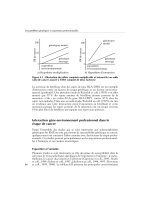
Pharyngeal morphology and adjacent structures are well shown by
cross-sectional techniques. The nasopharynx is closely related to the
foramina of the central skull base, accounting for the frequency of
neurological involvement in invasive nasopharyngeal carcinomas
(Fig. 10.13).
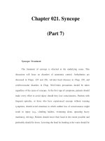
Nasopharynx
Uvula
Tonsil
Oropharynx
Epiglottis
Laryngopharynx
Sphenoid sinus
Foramen
rotundum
Vidian
(pterygoid)
canal
Pterygoid
processes
Lateral
pterygoid
muscle
Medial
pterrygoid
muscle
Torus tubarius
Fossa of
Rosenmuller
Fig. 10.13. Coronal CT through nasopharynx showing the pharyngeal recesses.
Also demonstrated are the foramen rotundum superolaterally, and the vidian
canal linking the pterygopalatine fossa and the foramen lacerum,
inferomedially.
Fig. 10.12. Diagram of
subdivisions of pharynx.
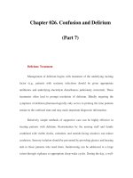
Temporalis
Masseter
Parotid
Medial
pterygoid
Internal
jugular vein
Prevertebral space
Retropharyngeal
space
Carotid sheath
Parapharyngeal
space
Parotid
space
Pharyngeal
mucosal space
Masticator
space
Buccal space
Internal
cartoid artery
Hard palate
Nasopharynx
Medial pterygoid
Parapharyngeal
space
Parotid
Medial pterygoid
Lateral
pterygoid
Levator
veli palatini
Parapharyngeal
space
Carotid sheath
Longus colli
Parotid gland
Masseter
Temporalis
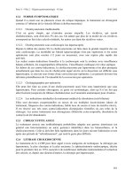
Fig. 10.14. Parapharyngeal and other deep spaces of the face and upper neck:
(a) schematic diagram through the nasopharynx showing the deep spaces of
the face on the right and some of their contents on the left. The central position
of the parapharyngeal space (shaded) is emphasised. (b)–(d) contiguous axial
T1W MRI superior to inferior demonstrating the high-signal fatty triangle of the
parapharyngeal space.
(a)
(b)
(c)
The extracranial head and neck jureerat thammaroj and joti bhattacharya
98
Hyoid bone
Thyrohyoid
membrane
Laryngeal
prominence
Median
cricothyroid
ligament
Lesser cornu
Greater
cornu
Thyroid
cartilage
Cricoid cartilage
Tracheal rings
Tip of epiglottis
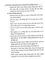
Fig. 10.15(a),(b). Diagram
of the cartilaginous
skeleton of the larynx:
(a) external view,
(b) cutaway view.
(a)
The oropharynx extends from the nasopharynx to the upper border
of the epiglottis inferiorly which, in turn, marks the upper limit of the
laryngopharynx. The tonsils appear as symmetrical soft tissue densi-
ties on either side of the airway on CT. Both tonsils and adenoids are
also well seen on MRI.
The laryngopharynx extends from the tip of the epiglottis to the
esophagus at the level of the sixth cervical vertebra. The pharyngeal
lumen is narrowest at its junction with the oesophagus where the
cricopharyngeus forms the upper esophageal sphincter.
The fascial layers of the neck and the parapharyngeal
space
Traditional anatomy describes several muscular triangles of the neck
but cross-sectional imaging in contrast emphasizes the importance of
the deep, fascia-lined spaces (Fig. 10.14) The fascia of the neck are
divided into superficial and deep layers. The deep fascia define the
deep spaces of the head and neck. These fascial layers form a barrier
against the spread of inflammatory or neoplastic disease. The parapha-
ryngeal space is easily recognized on both CT and MRI as a fatty trian-
gle (Fig. 10.14) whose diagnostic importance is in the characteristic
manner in which it is infiltrated, displaced or distorted by surround-
ing masses.
The larynx
The larynx forms the superior part of the lower respiratory tract
and lies anterior to the laryngopharynx. Its cartilaginous skeleton
(Fig. 10.15) contains the intrinsic muscles and the vocal folds. Laryngeal
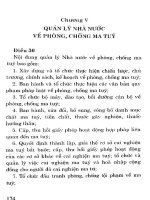
structures are well demonstrated by axial CT (Fig. 10.16) anteriorly lies
the epiglottis, which arises from the posterior surface of the thyroid
cartilage and is separated from the back of the tongue by paired
depressions, the valleculae. The piriform fossae of the laryngopharynx
lie between the laryngeal opening and the thyroid cartilage on
each side.
Hyoid bone
Glossoepiglottic
fold
Vallecula
Epiglottis
Fig. 10.16(a)–(i). Axial CT of the larynx from superior to inferior: (a) CT at level of
hyoid bone showing tip of epiglottis and the valleculae anteriorly. Note the
piriform fossae are below the level of the valleculae and are prominent laterally
on (c)–(f). Note also the normally fatty preepiglottic and paraglottic spaces and
that the fat is replaced by the glottic muscles at the level of the glottis.
Maxillary alveolus
Medial pterygoid
Parapharyngeal
space
Parotid
Epiglottis
Ventricular
ligament
Vocal
ligament
Cartilago
triticea
Superior
cornu
Aperture for internal
branch of recurrent
laryngeal nerve
Arytenoid
cartilage
Inferior cornu
(b)
(d)
Fig. 10.14. Continued
(a)
The extracranial head and neck jureerat thammaroj and joti bhattacharya
99
Vallecula
Mandible
Hyoid bone
Submandibular
gland
Sternocleido
mastoid
Epiglottis
Thyroid cartilage
Epiglottis
Pyriform fossa
Preepiglottic
space
Preepiglottic space
Thyroid cartilage
Aryepiglottic fold
Pyriform fossa
Aryepiglottic fold
Pyriform fossa
Fat in paraglottic
space
Thyroid cartilage
Arytenoid cartilage
Fat in paraglottic
space
Vocal fold
Arytenoid cartilage
Upper border of
cricoid cartilage
(b)
(c)
(d)
(e)
(f)
(g)
The extracranial head and neck jureerat thammaroj and joti bhattacharya
100
Vocal fold
Thyroarytenoid muscle
in paraglottic space
Arytenoid
cartilage
Ci id til
Trachea
Cricoid cartlage
Thyroid cartlage
Thyroid gland
(h)
(i)
Fig. 10.16(a)–(i). Continued
Uvula
Vestibular
fold
Ventricle
Vocal fold
Thyroid
gland
Thyroid cyst
Trachea
The inferior limit of the larynx is formed by the lower border of the
cricoid cartilage, which articulates with the arytenoid cartilages. The
arytenoids are capable of rotational and gliding movements, which
alter the tension of the vocal cords.
The vocal cords are attached to the arytenoids, which are useful
landmarks on CT to identify the vocal folds. The interior of the larynx
is marked by the parallel bands of the true vocal cords inferiorly, and
the vestibular folds or false cords superiorly. Between these is the slit-
like cavity of the laryngeal ventricle. These structures are well seen
in the coronal plane, on soft tissue radiographs, and on MRI scans
(Fig. 10.17).
Fig. 10.17(a),(b). Coronal
views of the larynx:
(a) soft tissue
radiograph and
(b) coronal MRI.
(a)
Vestibular
fold
Ventricle
Vocal fold
Trachea
Cricoid
cartilage
Thyroid
cartilage
Pyriform
fossa
Vestibule
(b)
The extracranial head and neck jureerat thammaroj and joti bhattacharya
101
Thyroid
muscle
Hyoid
Sternothyroid
muscle
Cricothyroid
muscle
Isthmus
Thyroid
cartilage
Cricoid
cartilage
Thyroid
gland
Trachea
Oesophagus
Fig. 10.18(a),(b). Diagrams of thyroid gland: (a) frontal view (b) cross-section.
Internal jugular vein
Common carotid artery
Trachea
Thyroid gland
Sternocleidomastoid
Phrenic nerve
Scalenus
anterior
Brachial
plexus
Scalenus
medius
Longus colli
Oesophagus
Vagus nerve
(a)
(b)
Thyroid and parathyroid glands
The thyroid gland extends on either side of the trachea linked by
an isthmus (Fig. 10.18). The gland is enclosed by the deep cervical
fascia and covered anteriorly by the strap muscles. Current imaging
techniques show a relatively homogeneous texture. It is highly
vascular however, and demonstrates intense contrast enhance-
ment on CT and MRI (Fig. 10.19). Its superficial location makes
the thyroid gland an ideal organ for ultrasound examination
(Fig. 10.20).
Radionuclide imaging may be performed with [Tc
99 m
] pertechnetate,
which is trapped by the thyroid in the same way as iodine and gives
morphological information. It will reveal the presence of ectopic
thyroid tissue (Fig. 10.21). Functional data can be obtained with the use
of [
23
I].
The normal parathyroid glands (four in number) are too small to be
identified by imaging. Standard now for parathyroid tumour pick-up.
Vertebral artery
and vein
Common
carotid artery
Trachea
Thyroid gland
Sternocleidomastoid
muscle
Internal
jugular
vein
C7 vertebral
body
Oesophagus
External
jugular
vein
Fig. 10.19. Contrast-enhanced CT of the neck at the level of the C7 vertebra. The
thyroid gland shows intense enhancement. Posterolaterally lie the carotid
sheaths. The vertebral vessels have not yet entered the foramen
transversarium.
Tracheal ring
Sternocleidomastoid
Thyroid gland
Fig. 10.20. Ultrasound of the thyroid gland in transverse section. The lobes and
isthmus of the thyroid gland with their normally homogeneous texture, lie on
either side of the highly echoic tracheal rings. Superficial to the gland are the
relatively hypoechoic sternocleidomastoid muscles.
Fig. 10.21. Thyroid
scintigraphy.
The extracranial head and neck jureerat thammaroj and joti bhattacharya
102
The craniocervical lymphatic system
Normal cervical lymph nodes (Fig. 10.22) are not readily identified by
CT or MRI, but when seen, are of homogeneous soft tissue density or
intensity, respectively, and are less than 1.5 cm diameter in the sub-
mandibular or jugulodigastric region. Nodes elsewhere in the neck
are considered abnormal if larger than 1 cm.
Lymph drainage is ultimately via the jugular trunks into the thoracic
duct on the left and either into the right lymphatic duct or directly into
the junction of the subclavian and internal jugular veins on the right.
The cervical vasculature
The right common carotid artery arises from the brachiocephalic
artery behind the right sternoclavicular joint. The left common
carotid artery arises directly from the aortic arch. They lie within the
carotid sheath with the internal jugular vein laterally (Fig. 10.18, 10.19)
and the vagus posteriorly. The common carotid artery divides at the
level of the fourth cervical vertebra (Fig. 10.23). The smaller external
Facial nodes
Submental
nodes
Submandibular
nodes
Internal jugular nodes
(deep cervical chain)
Anterior jugular
nodes
Supraclavicular
nodes
Posterior triangle nodes
Mastoid nodes
Occipital
nodes
Parotid nodes
Fig. 10.22. Diagram of the cervical lymph nodes.
Occipital artery
Facial artery
External carotid
artery
Internal carotid
artery
Superior thyroid
artery
Catheter
Fig. 10.23(a),(b).
Angiogram
demonstrating the
common carotid
bifurcation and external
carotid arteries
(a) anteroposterior
(b) lateral. In this subject
the bifurcation is at the
C3/4 level.
Fig. 10.23. Continued
Occipital artery
Internal carotid
artery
Common carotid
artery
Superior thyroid
artery
External carotid
artery
Lingual artery
Facial artery
Maxillary artery
(a)
(b)
Fig. 10.24. (a) B-mode
sonogram of the
common carotid
bifurcation. Doppler
waveforms of the
internal (b) and external
(c) carotid arteries.
(a)
(b)
(c)
carotid lies initially anteromedial to the internal carotid artery. These
vessels are well demonstrated by conventional, CT or MR angiography.
The carotid bifurcation is well demonstrated by ultrasound (Fig. 10.24)
which shows both structure (B-mode) and flow characteristics
(Doppler study).
The extracranial head and neck jureerat thammaroj and joti bhattacharya
103
Vertebral artery
Subclavian
artery
Catheter
Fig. 10.25(a)–(e). Vertebral
angiography: (a) origin
of the left vertebral
artery. (b),(c)
anteroposterior and
(d),(e) lateral views of
the cervical portion of
the vertebral artery.
Note the muscular
branches, branches to
the anterior spinal
artery and the
anastomoses with the
occipital artery.
The vertebral artery is the first branch of the subclavian artery and
traverses the foramina transversaria (entering at the sixth cervical
vertebra) (Fig. 10.25), supplying the cervical musculature and con-
tributing to the spinal arteries, then passing intracranially through
the foramen magnum.
(a)
(b)
(c)
Muscular
branches
Vertebral
artery
Anterior spinal
artery
Anastomosis
with occipital
artery branches
Muscular
branches
Anterior spinal
artery
(e)
(d)
The external carotid artery supplies the upper cervical organs,
facial structures, scalp, and dura. Traditionally, eight branches
are described but individual variation is common and many anasto-
moses exist. The external carotid divides within the parotid gland
into the superficial temporal and maxillary arteries.
The maxillary artery runs forwards from the parotid gland,
through the infra-temporal fossa into the pterygopalatine fossa.
The largest branch is the middle meningeal artery which ascends
passing through the foramen spinosum into the middle cranial
fossa. Its’ terminal branches supply the nasal cavity (sphenopalatine
artery), with other branches supplying the pharynx, maxillary sinus,
palate and orbit.
The extracranial head and neck jureerat thammaroj and joti bhattacharya
104
T1
C8
C7
C6
C5
Nerve roots
Nerve
trunks
Anterior
division
Posterior
division
Cords
Musculocutaneous
nerve
Circumflex
axillary nerve
Radial nerve
Median nerve
Pectoralis minor
muscle
Subclavian
artery
Ulnar nerve
Fig. 10.26. Diagram of the
brachial plexus.
T1
C7
C6
C5
C4
Vertebral
artery
Branchial
plexus
Branchial
plexus
Scalenus
posterior
Fig. 10.27. MRI of the
brachial plexus.
Sternocleidomastoid
Scalenus
anterior
Scalenus
medius
Trapezius
Levator
scapulae
Brachial plexus
Subclavian
artery
(a)
(b)
The extracranial venous drainage is mainly into the external jugular
system, thence to the subclavian veins.
Brachial plexus
The brachial plexus is formed from the anterior rami of the fifth cervi-
cal to the first thoracic nerve roots. The fourth cervical and second
thoracic roots may also contribute. The alternate division and union of
these roots give rise to the complexity of the plexus (Fig. 10.26). MRI
scans in the coronal and oblique planes are the most useful studies
(Fig. 10.27).
105
General overview
The vertebral column forms the central axis of the skeleton and con-
sists of 33 vertebrae.
There are seven cervical, twelve thoracic and five lumbar vertebrae
(the true, “moveable” vertebrae), and caudally there are five sacral and
four coccygeal segments, all of which are fused as the sacrum and
coccyx, respectively.
Imaging methods
Plain radiography
Plain radiography remains the most commonly performed investiga-
tion of the vertebral column, especially after trauma. The spatial reso-
lution of radiographs is high and they are simple to acquire. Vertebral
alignment is easy to assess and bone detail is well shown. Soft tissue
detail is poor.
Computed tomogaphy (CT)
CT provides cross-sectional images of bony and soft tissue elements
of the vertebral column. Because CT is a digital technique, the images
can be manipulated to optimize either bone or soft tissue detail
(Fig. 11.1). The set of axial scans can also be summated and reformatted
to produce sagittal and coronal images. CT utilizes ionizing radiation
and the dose to the pelvis, in particular to the reproductive organs,
should be borne in mind when requesting imaging of the lumbosacral
region.
CT is displayed using a gray scale based on the degree to which a
tissue attenuates the X-ray beam. The two extremes are bone, which
appears white and which is radio-opaque and air, which is radiolucent
and appears black. Fat and cerebrospinal fluid are also radiolucent.
Only in the upper cervical column can the spinal cord be discrimi-
nated from the surrounding CSF. It is possible to inject iodinated con-
trast agent via a lumbar puncture and perform a CT myelogram. This
reveals structural detail within the dural sac. The contour of the spinal
cord and nerve roots can thus be demonstrated but not any intrinsic
detail (Fig. 11.2). A myelogram utilizing conventional radiography may
be obtained prior to the patient undergoing CT.
Bone-targeted CT is valuable in suspected vertebral trauma but, in
other cases, CT of the vertebral column is usually reserved for the
minority in whom MRI is contraindicated.
Magnetic resonance imaging (MRI)
MRI is the primary imaging method for the vertebral column. It pro-
vides images in multiple planes, does not use ionizing radiation and
displays excellent anatomical and pathological information. A typical
Section 4
The head, neck, and vertebral column
Chapter 11 The vertebral column
and spinal cord
CLAUDIA KIRSCH
Intervertebral
disk
Ligamentum
flavum
(a)
(b)
Applied Radiological Anatomy for Medical Students. Paul Butler, Adam Mitchell, and Harold Ellis (eds.) Published by Cambridge University Press. © P. Butler,
A. Mitchell, and H. Ellis 2007.
Superior
articular
process
Inferior
articular process
Facet joint
Fig. 11.1. Axial CT at the level of L3/4 intervertebral disk: (a) soft tissue, (b) bone windows.
The vertebral column and spinal cord claudia kirsch
106
MRI series will consist of T1W and T2W sagittal and axial images.
Further coronal images and intravenous gadolinium DTPA contrast
administration may be undertaken depending on the clinical picture.
The tissue discrimination of MRI is superior to CT. MRI is the only
method to show an intrinsic abnormality of the spinal cord substance.
On T1W images the CSF is dark and, in general, this sequence shows
the anatomy. On T2W images the CSF appears white and thus there is
a myelographic effect. T2W sequences, in general, demonstrate
pathology.
There are four curves in the sagittal plane: the cervical and lumbar,
which are convex anteriorly (lordotic) and the thoracic and sacrococ-
cygeal curves, which are concave anteriorly (kyphotic) (Fig. 11.3).
The kyphoses are primary curves, present in the fetus; the lordotic
curves develop later in life and are secondary, serving to strengthen
the column.
Despite regional differences, a typical vertebra can be described
with a body anteriorly and a neural arch posteriorly (Fig. 11.4). The
neural arch surrounds the spinal canal and consists, on each side, of
a pedicle laterally and a lamina posteriorly. A transverse process
extends laterally and the laminae fuse posteriorly to form the spinous
process. The intervertebral canals transmit the segmental spinal
nerves between adjacent pedicles.
The vertebral body consists of central cancellous (spongy) bone with
a rim of dense cortical bone.
The vertebral bodies are important sites for hematopoiesis contain-
ing red marrow in the young, converting to yellow (fatty) marrow
with increasing age.
The intervertebral disc is a cartilaginous cushion between adjacent
vertebral bodies, (Fig. 11.3). Each consists of a central nucleus pulposus
surrounded by an annulus fibrosus.
During childhood the disks are highly vascular but, by the age of 20
years, the normal disk is avascular. With increasing age, the disk
undergoes progressive dehydration with loss of height.
Foramen
transversarium
Ventral
nerve root
Dorsal
nerve root
Spinal cord
Fig. 11.2. Axial CT myelogram (a) cervical spine, (b) lumbar spine.
CSF opacified with
iodinated contrast
medium
Nerve roots of the
cauda equina
Fig. 11.3. T1W, T2W
sagittal MRI, vertebral
column.
(a)
(b)
(a)
(b)
The vertebral column and spinal cord claudia kirsch
107
There are regional variations in disc morphology. In the cervical and
lumbar regions the disks are thicker anteriorly and contribute to the
lordoses. The disks are thinnest in the upper thoracic region and
thickest in the lumbar region. Overall, the disks account for 20% of
the total height of the vertebral column.
The facet joints are synovial articulations in the neural arches,
which unite the posterior elements of the vertebral column (Fig. 11.1).
The articular processes project superiorly and inferiorly at the junc-
tion between the lamina and pedicle. The articular process of the
vertbra above (i.e., its inferior facet) is posterior to that of the vertebra
below (i.e., its superior facet).
The vertebral canal
The vertebral canal transmits the spinal cord and, in the lumbar
region, the cauda equina. It is formed by the posterior margins of the
vertebral bodies and discs anteriorly, and the pedicles and laminae
(the neural arch) posteriorly.
The intervertebral canal (the neural foramen)
The spinal nerves arise from the spinal cord and leave the spinal canal
through the intervertebral canals, each of which is situated between
adjacent pedicles (Fig. 11.5). The nerves are accompanied by blood
vessels and are supported by extradural fat within each canal.
The ligaments of the vertebral column
A number of ligaments strengthen the vertebral column (Fig. 11.6).
The anterior longitudinal ligament runs superoinferiorly between the
anterior surfaces of the vertebral bodies from the occiput to the
sacrum. The posterior longitudinal ligament is applied to the posterior
surfaces and narrows as it passes downward. The ligamentum flavum
joins adjacent laminae and the interspinous ligaments run between
the spinous processes.
In the axial plane the ligamentum flavum appears V shaped and is
thickest in the lumbar region. It is the only spinal ligament having
elastic properties, increasing in length in flexion.
The vertebral column can be considered as a three-column struc-
ture. The anterior column is formed by the anterior longitudinal liga-
ment, the anterior annulus fibrosus, and the anterior part of the
vertebral body. The middle column comprises the posterior longitudi-
nal ligament, the posterior annulus fibrosus, and the posterior part of
the vertebral body. The posterior column consists of the neural arch
and posterior ligamentous complex. This concept has implications for
spinal stability following trauma.
Exiting nerve root
Body
Superior
costal facet
Transverse process
Transverse
costal facet
Lamina
Spinous process
Superior
costal facet
Superior
articular facet
Pedicle
Transverse
costal facet
Inferior
costal facet
Inferior
articular process
Fig. 11.4. A typical vertebra (T6): (a) superior, (b) lateral views.
(a)
(b)
Fig. 11.5. T1W MRI, parasagittal plane, the lumbar neural foramina.
The vertebral column and spinal cord claudia kirsch
108
The craniocervical junction and cervical vertebral column
The craniocervical junction (CVJ) is composed of the occiput, atlas,
and axis, and supporting ligaments, enclosing the soft tissues of the
medulla, spinal cord, and lower cranial nerves. MRI is the most appro-
priate means of showing the relationship of bone and soft tissue in
this important region (Fig. 11.7). CT demonstrates the bony anatomy,
(Fig. 11.8).A variety of congenital anomalies of the bony skull base can
lead to basilar invagination, when the vertebral column extends into
skull base. A similar result, better described as cranial “settling,” can
occur in the erosive arthropathies due to ligamentous damage.
There are seven cervical vertebrae. The atlas vertebra (C1) is a ring of
bone with no vertebral body (Fig. 11.9). It articulates superiorly with
the occipital condyles of the skull as the atlanto-occipital joints.
Think of the Greek myth of Atlas who carried the world on his
shoulders and you realize the responsibility of the first vertebra as it
carries your “world” or head on your shoulders!
The axis vertebra (C2) has a superior extension, the odontoid
process (or dens) which represents the body of C1 (Fig. 11.10). The ante-
rior arch of C1 is maintained in a fixed position relative to the dens by
the transverse ligament, which attaches to the lateral masses of C1.
Four joints are formed between C1 and C2, namely the anterior arch
of C1 and the dens, the dens and the transverse ligament, and the
right and left articular facets. Damage to the ligament, either by
trauma or due to an erosive arthropathy, like rheumatoid arthritis,
can result in atlanto-axial subluxation and cervical cord compression.
C3 to C6 may be regarded as typical (Fig. 11.11). The small, oval
vertebral bodies increase in size to C7. The superior projection of
each vertebra, the “uncinate process,” forms a rim or flange, which
indents the posterior–lateral disk and vertebrae above, creating the
“uncovertebral joint.” The short pedicles extend laterally from the
anterior body forming a bridge to the articular pillars, which bear the
inferior and superior articular facets. The spinous processes may be
bifid and the transverse processes terminate with anterior and
posterior tubercles. Each transverse process encloses the foramen
transversarium, which transmits the vertebral arteries and veins on
each side. C7, the vertebra prominens, has a long, non-bifid spine,
and no anterior tubercle on its transverse process. Its foramen trans-
versarium is often small; it only transmits small tributaries of the
vertebral vein – the artery enters at C6. The vertebral arteries arise
from the subclavian arteries, enter the foramen transversarium of C6,
traverse the successive foramina transversaria above this level and
enter the skull through the foramen magnum. The cervical canal is
funnel-shaped in the sagittal plane, widest superiorly. It is triangular
in cross-section.
In addition to making sure that the lateral masses of C1 are aligned
appropriately on C-2, five important contour lines are evaluated on
lateral cervical spine plain films, (Fig. 11.9(c)). The first is the anterior
soft tissue or prevertebral space. At C-3, the prevertebral soft tissues
should be no more than 4–5 mm, with a maximum about 7 mm. At
C6, this increases to approximately 10–20 mm. In children, this space
may measure 14 mm and up to 22 mm in adults, with the soft tissues
usually measuring 15 mm on average. The next lines evaluated include
the anterior and posterior spinal lines extending along the anterior
and posterior vertebral bodies, respectively. Lastly, the spinolaminal
line and spinous process line should be evaluated for appropriate
alignment.
Anterior arch of atlas (C1)
Odontoid peg (dens)
Spinal cord
Spinous process
Fig. 11.7. T2W sagittal MRI, cervical spine.
Atlas, C1
Occipital
condyle
Axis, C2
Fig. 11.8. Coronal CT reformat, the craniovertebral junction.
Posterior
longitudinal ligament
Intervertebral canal
Ligamentum flavum
Supraspinous ligament
Interspinous ligament
Anterior
longitudinal ligament
Pedicle
Posterior
longitudinal
ligament
Intervertebral disk
(a)
(b)
Fig. 11.6. The ligaments of the vertebral column, (a) lateral view, (b) vertebral
bodies viewed from behind.
The vertebral column and spinal cord claudia kirsch
109
The thoracic vertebral column
There are 12 thoracic vertebrae distinguished by articulations for the
ribs (Fig. 11.12). The vertebral bodies have a slight wedge-shape anteri-
orly. They also bear demifacets for the ribs on the superior and infe-
rior vertebral bodies. Otherwise, the anatomy conforms to that of the
“typical vertebra” given above. The annulus fibrosus, ALL, and PLL are
the thickest in this region.
The ribs attach at two places: the head of the rib attaches to the
vertebrae at the disk and additionally the tubercle of the rib attaches
Tectorial membrane (cranial
extension of PLL)
Vertebral artery
Apical
ligament
of dens
Anterior
arch of C1
Transverse
ligament
of dens
Posterior
longitudinal
ligament (PLL)
Anterior
longitudinal
ligament (ALL)
Fig. 11.10. The
craniovertebral
ligaments viewed in
sagittal section.
Body
Foramen
transversarium
Pedicle
Superior
articular
facet
Lamina
Articular pillar
Spinous process
Fig. 11.11. Cervical
vertebra.
Pedicle
Spinous process
Rib
Superior articular facet
Rib
Inferior articular facet
Intervertebral canal
Vertebral body
Fig. 11.12. Thoracic spine radiographs: (a) anteroposterior, (b) lateral views.
(a)
(b)
Lateral mass
of atlas, C1
Mandibular
dentition
Odontoid peg
(dens)
of axis, C2
Axis, C2
Prevertebral
soft tissue
Atlas, C1
Fig. 11.9. Cervical spine radiographs: (a) anteroposterior, (b) per oral, (c) lateral
views.
Uncovertebral joint
Transverse process
Spinous process
Transverse process of T1
(a)
(b)
(c)
The vertebral column and spinal cord claudia kirsch
110
to the transverse process costotransverse joint (Fig. 11.13). Typically,
therefore the ribs arise posteriorly between vertebrae. The first rib
articulates only with T1 and similarly the tenth, eleventh, and twelfth
ribs articulate only with T10, T11, and T12 vertebrae. At remaining
levels, demifacets superior and inferior to the disk communicate with
the head of the rib creating a costovertebral synovial joint. Therefore,
the ribs arise posteriorly between vertebrae. In the thoracic region the
canal is constant in size and circular in cross-section.
The lumbar vertebral column
There are five lumbar vertebrae, the third (L3) being the largest
(Fig. 11.14). Lumbar vertebrae have square-shaped anterior vertebral
bodies covered by fenestrated cartilage attached to the adjacent
disks. Projecting posteriorly are bilateral pedicles composed of thick
cortical bone connecting to lamina forming the spinal canal. The artic-
ular facets face each other in the sagittal plane (Fig. 11.15), and the
transverse distance between the pedicles increases (the interpedicular
distance) from L1 to L5. L5 is somewhat atypical with a wedge-shaped
body, articulating inferiorly with the sacrum. Not infrequently, it may
be fused, wholly or partly, with the body of the sacrum (“sacralization
of L5”). Extending from the pedicles is a bony plate called the pars
articularis from which extend the superior and inferior articular
facets. The posterior superior articular facet of an inferiorly located
vertebra connects to the posterior inferior facet of the superior verte-
bra above creating a diarthrodial synovial lined joint, surrounded by a
fibrous capsule posterolaterally with absence of the joint capsule ante-
riorly, where the ligamentum flavum and synovial membrane are
present, (Fig. 11.16).
The spinal cord
The spinal cord extends from the foramen magnum to the level of the
first or second lumbar vertebrae. It is oval and elliptical in the cervical
spine (Fig. 11.17), more rounded in the thoracic region (Fig. 11.18)
always being wider in the transverse plane. A cleft anteriorly is
referred to as the ventral median fissure and a small shallow sulcus is
Superior articular process
Inferior articular process
Spinous process
Pedicle
Sacroiliac joint
Fig. 11.14. Lumbar spine radiographs: (a) anteroposterior, (b) lateral views.
Intervertebral canal
Vertebral body
Pedicle
Superior articular
process of L4
Transverse process
Superior articular facet
Inferior articular facet
Pedicle
Fig. 11.15. Lumbar spine radiograph, oblique projection.
(a)
(b)
Vertebral body
Spinal cord
Costovertebral
articulation
Costotransverse
articulation
Fig. 11.13. Axial CT myelogram, thoracic spine.
The vertebral column and spinal cord claudia kirsch
111
Spinal cord
Fig. 11.17. GRE axial MRI, cervical spine. Note that this sequence (gradient
recalled echo) demonstrates gray matter within the spinal cord.
Spinal cord
Fig. 11.18. T2W axial MRI, thoracic spine.
Exiting nerve root,
part of the cauda
equina
Fig. 11.19. T2W sagittal MRI, lumbar spine showing the cauda equina.
Dorsal root ganglion
Fig. 11.20. T1W axial image, lumbar vertebra.
noted posteriorly. In cross-section the cord has central gray matter
shaped like a butterfly H-shaped pattern surrounded by white matter.
The lower end of the spinal cord tapers to form the conus medullaris
and from the conus the thin filum terminale extends to the coccyx.
The caliber of the spinal cord increases in two regions as the cervi-
cal (C5–T1 segments) and lumbar (L2–S3 segments) expansions con-
cerned with the arms and legs, respectively.
The spinal nerves
Since the spinal cord is shorter than the vertebral column, the spinal
nerves take a progressively oblique course caudally to emerge through
the intervertebral canals. Below the termination of the spinal cord,
the nerve roots in the lumbar region pass almost vertically down to
form the cauda equina (horse’s tail) (Fig. 11.19).
There are 31 pairs of spinal nerves: 8 cervical, 12 thoracic and 5
lumbar. Each spinal nerve is formed from a dorsal (posterior) sensory
root and a ventral (anterior) motor root emerging from the spinal
cord. The ventral roots contain axons of the neurons in the spinal gray
matter. The neurons of the dorsal roots are found in the ganglion
borne by each dorsal root. The ganglion is usually situated in the
intervertebral canal (Fig. 11.20) and distal to this ventral and dorsal
roots merge to form the spinal nerve (Fig. 11.2a). C1 root exits between
the occiput and C1 vertebra. Each cervical nerve root therefore exits
above the correspondingly numbered vertebra. C8 root exits between
C7 and T1 vertebrae. Because of this, thoracic nerve roots exit below
the correspondingly numbered thoracic vertebra.
In the lumbar spine each root leaves the spinal canal laterally below
the pedicle of the corresponding vertebra and above the disk.
Meninges
The spinal and cranial meningeal sheaths are continuous. The spinal
dural sac extends from the posterior cranial fossa to the second sacral
segment. It surrounds the spinal cord, nerve roots and cerebrospinal
fluid (CSF).
Superior
articular
process
Facet joint
Inferior
articular
process
Ligamentum
flavum
Fig. 11.16. T1W axial MRI, lumbar vertebra.
The vertebral column and spinal cord claudia kirsch
112
Within the dura is the avascular arachnoid and the pia mater, the
second component of the leptomeninges, forms a layer over the spinal
cord. Between the two is the subarachnoid space, which contains
cerebrospinal fluid.
The blood supply to the spinal cord
The cervical spinal cord blood supply is from the anterior spinal artery
and paired posterior spinal arteries. The anterior spinal artery is
formed superiorly from branches that extend inferiorly from both of
the vertebral arteries (Fig. 11.21). It supplies the anterior two-thirds of
the cord. This critical area includes the corticospinal and spinothala-
mic tracts as well as the central gray matter anterior column.
The posterior spinal arteries, which also arise from the vertebral
arteries, supply the posterior one-third of the cord, including the
posterior columns and central gray matter posterior horn.
The spinal arteries, running the length of the cord, also receive
numerous contributions from various cervical arteries and from the
segmental thoracic intercostal and lumbar arteries. These feeding
vessels extend through the intervertebral canals and bifurcate into
anterior and posterior vessels extending along the dorsal and ventral
nerve roots. One very important major contribution comes from the
Artery of Adamkiewicz, which usually arises from the left side and/or
the intercostals arteries at the T-9 to T-12 vertebral levels. This vessel
comes into the spinal canal with nerve roots and has a classic
“hairpin loop” (Fig. 11.22). This vessel supplies the anterior spinal
cord in the thoracolumbar region via a large descending vessel
which anastamoses with the posterior spinal arteries at the conus.
Draining veins leave the spinal cord through the intervertebral
canals to join an extensive interconnecting plexus of veins in the
epidural space.
Right vertebral artery
Radicular feeding artery
Anterior spinal artery
Fig. 11.21. Vertebral angiogram showing the anterior spinal artery and radicular
arteries.
The artery of
Adamkiewicz
Intercostal artery
Fig. 11.22. The artery of Adamkiewicz arising from the left intercostal artery
at T9 level.
The skeletal anatomy of the upper limb is well demonstrated on con-
ventional plain radiographs, which are quick and simple to acquire
and have better spatial resolution than computed tomography (CT) or
magnetic resonance imaging (MRI). Radiographs are usually acquired
in two planes, at 90 degrees to one another, to overcome issues such
as foreshortening and overlying bony structures. When imaging
complex joints such as the shoulder, supplementary views may also be
required.
In complex orthopedic or trauma cases, 3-D image reconstructions
of CT examinations provide excellent visualization of regions of
abnormal skeletal development or complex fractures. MRI is more
often applied in the assessment of soft tissues, including the joints,
the neurovascular structures, especially the brachial plexus, and the
bone marrow. Ultrasound (US) is used increasingly commonly in
the evaluation of the superficial soft tissue structures, such as the
tendons of the rotator cuff within the shoulder and the tendons of
the wrist.
Arthrography involves the injection of a contrast agent such as air
or iodinated contrast medium into a joint space to allow visualiza-
tion of the joint, its capsule and articular surfaces under
fluoroscopy. This technique has been largely superseded by other
imaging modalities such as MRI, although arthrography combined
with MR or CT, where gadolinium or iodinated contrast medium is
instilled into the joint prior to imaging, gives exquisite detail of the
joint spaces and any disruption of the joint capsule or supporting
structures.
Angiography and venography are used to assess arterial and venous
anatomy for reasons such as the placement of central venous
catheters, planning the formation and maintenance of arteriovenous
fistulas and the management of arterial trauma. This can be per-
formed via traditional catheter angiography techniques or by digitally
reconstructing the vascular detail from a contrast medium enhanced
CT or magnetic resonance (MR) examination
In most musculoskeletal cases, more than one imaging modality is
required to acquire the breadth of radiological information necessary
to make a full and accurate diagnosis.
The shoulder and upper arm
The shoulder girdle
The shoulder girdle connects the upper limb to the axial skeleton,
allowing movement at both the shoulder joint and the scapulotho-
racic joint (Fig. 12.1). The weight of the arm is transmitted to the trunk
primarily via the clavicle.
The scapula
The scapula overlies the posterolateral aspect of the chest wall, its
inner surface closely applied to the posterior aspects of the second to
113
Section 5 The limbs
Chapter 12 The upper limb
ALEX M. BARNACLE
and ADAM W. M. MITCHELL
Applied Radiological Anatomy for Medical Students. Paul Butler, Adam Mitchell, and Harold Ellis (eds.) Published by Cambridge University Press. © P. Butler,
A. Mitchell, and H. Ellis 2007.
Fig. 12.1. Anteroposterior radiograph of the left shoulder.
seventh ribs. The anterior and posterior surfaces of the scapula give
attachment to many of the muscles of the rotator cuff. The rotator
cuff is the term used to describe the tendons of the four smaller
muscles surrounding the shoulder joint; the tendons are intimately
related to the capsule of the shoulder joint (Fig. 12.2). Subscapularis
attaches to the convex costal surface of the scapula and inserts onto
the lesser tubercle of the humerus. Supraspinatus arises from the
supraspinous fossa of the posterior aspect of the scapula and inserts
onto the greater tubercle of the humerus. Adjacent to this, infraspina-
tus arises from the infraspinous fossa and also attaches to the greater
tubercle. The supraspinous and infraspinous fossae communicate
laterally around the base of the spine of the scapula. Teres minor
arises from the lateral margin of the scapula and inserts inferiorly
onto the greater tubercle of the humerus.
Laterally, the angle of the scapula forms the articular surface of the
bone, known as the glenoid fossa; this articulates with the humeral
head. The bony tubercles above and below the glenoid fossa give
attachment to the long heads of biceps and triceps respectively. The
projection known as the acromion is formed by the flattened lateral
extension of the spine of the scapula. It articulates with the lateral
end of the clavicle and overlies the shoulder joint, providing some
protection for both the joint and the overlying supraspinatus tendon
of the rotator cuff. Medial to the acromion, the coracoid process of the
scapula projects anteriorly, giving attachment to the short head of
biceps, pectoralis minor, and coracobrachialis, and to the coracoclavic-
ular ligament. Latissimus dorsi, teres major, and serratus anterior
attach to the inferior angle of the body of the scapula. The acromion
and the spine of the scapula give attachment to larger muscles of the
shoulder girdle, trapezius, and deltoid.
The clavicle
The clavicle is an S-shaped bone that develops from a mesenchymal or
membranous origin and is the first bone in the body to ossify. It is
unusual in that it does not contain a medullary cavity. The clavicle
articulates with the manubrium of the sternum and the first costal
cartilage medially, forming the sternoclavicular joint. The costoclavic-
ular ligament arises from the inferior surface of the medial clavicle
and inserts onto the upper surface of the first costal cartilage and the
first rib. Laterally, the clavicle articulates with the acromion of the
scapula, the coracoclavicular ligament arising from the inferior
surface of the clavicle just medial to this joint. The large muscles of
the shoulder girdle gain some of their attachments from the clavicle:
pectoralis major, deltoid, sternocleidomastoid and trapezius.
The clavicle transmits part of the weight of the upper limb to the
trunk and, with the scapula, allows the arm to swing clear of the
trunk.
The sternoclavicular joint
The fibrocartilaginous sternoclavicular joint is formed by the artic-
ulation of the manubrium sternum and the first costal cartilage with
the medial aspect of the clavicle. The strong fibrous costoclavicular
ligament arises from the inferior surface of the clavicle just lateral
to the sternoclavicular joint, attaching to the superior aspect of the
first rib and stabilizing the joint. Further stability is afforded by the
The upper limb alex m. barnacle and adam w. m. mitchell
114
(a)
(b)
Fig. 12.2. T2 weighted MR images acquired in the sagittal plane (lateral view): (a) image through the body of the scapula, the coracoid process and acromion. The
muscles of the rotator cuff surround the body of the scapula; (b) More lateral image through the humeral head showing the tendons of the rotator cuff before their
insertion onto the humerus.