System Analysis, Design, and Development Concepts, Principles, and Practices phần 2 ppsx
Bạn đang xem bản rút gọn của tài liệu. Xem và tải ngay bản đầy đủ của tài liệu tại đây (2.54 MB, 84 trang )
tures of each entity within the system hierarchy. Third, the system elements serve as an initial start-
ing point for allocations of multi-level performance specification requirements.
Despite strong technical and analytical skills, engineers are sometimes poor organizers of
information. Therein lies a fundamental problem for the engineering of systems. Being able to
understand and frame/structure the problem is 50% of the solution. The organizational framework
of the System Element Architecture concept provides the framework for defining the system and
its boundaries.
The challenge in analyzing and solving system development and engineering problems is being
able to identify, organize, define, and articulate the relevant elements of a problem (objectives,
initial conditions, assumptions, etc.) in an easy-to-understand, intelligible manner that enables us
to conceptualize and formulate the solution strategy. Establishing a standard analytical framework
enables us to apply “plug and chug” mathematical and scientific principles, the core strength of
engineering training, to the architecture of the system.
Problem Solving to Reduce Complexity
System analysis and engineering is deeply rooted in the concept of analytically decomposing large,
complex problems into manageable problems that can be easily solved. Unfortunately, many engi-
neers lack the training to be able to organize, structure, and analyze a system problem around its
system elements.
In practical terms, you should ingrain this concept as a basis for organizing and structuring rel-
evant parts your problem. However, a word of caution: Avoid temptation to tailor out relevant
system elements without supporting rationale that can withstand professional scrutiny. You may
pay a penalty in overlooked system design issues.
For now, we have one remaining system element concept to introduce—entity relationships
(ERs).
8.4 UNDERSTANDING SYSTEM ELEMENT
ENTITY RELATIONSHIPS
The architectural concept discussions that follow describe the entity relationships (ERs) between
each of the System Elements identified in Table 8.1. Before we begin these discussions, let’s intro-
duce the types of relationships that exist between these elements.
System element interactions can be characterized by two types of relationships: logical and
physical. Perhaps the best way to think of logical and physical relationships is to focus on one topic
at a time and then integrate the two concepts.
Logical Entity Relationships
The first step in identifying logical entity relationships is to simply recognize and acknowledge that
some form of association exists through deductive reasoning. You may not know the physical
details of the relationship—that is, how they link up—but you know a relationship does or will
exist. Graphically, we depict these relationships as simply a line between the two entities.
The second step is to characterize the logical relationship in terms of logical functions—
that is, what interaction occurs between them—must be provided to enable the two entities to
associate with one another. When we assemble the logical entities into a framework that graphi-
cally describes their relationships, we refer to the diagram as logical architecture. To illustrate, let’s
assume we have a simple room lighting situation as shown in Figure 8.3.
8.4 Understanding System Element Entity Relationships 71
Simpo PDF Merge and Split Unregistered Version -
EXAMPLE 8.1
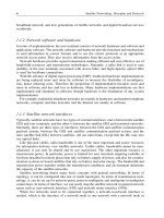
Room Lighting—Logical Architecture Entity Relationships The top portion of Figure 8.3 depicts a simple
ROOM LIGHTING SYSTEM consisting of a PERSON (entity) desiring to control a room LIGHT SOURCE
(entity). As a logical representation, we draw a line between the PERSON (entity) and the LIGHT SOURCE
(entity) to acknowledge the relationship. Thus, we state that the PERSON (entity) has a logical association
or entity relationship with the LIGHT SOURCE.
Author’s Note 8.3 Observe that we are interested in simply establishing and acknowledging
the need for the logical relationship—meaning capability. The need for the capability serves as the
basis for a specification requirement—meaning WHAT—and HOW much illumination is required.
HOW this logical entity relationship is physically implemented via design and components becomes
the basis for engineering analysis and design—with the application of mathematical and scientific
principles.
Next, we need a control mechanism for the LIGHT SOURCE (logical entity), which derives its energy from
a POWER SOURCE (logical entity). We complete the representation by connecting the PERSON (logical
entity) with the LIGHTING CONTROL (logical entity). The LIGHTING CONTROL enables the flow of
current from the POWER SOURCE to the LIGHT SOURCE. When energized, the LIGHT SOURCE illumi-
nates the room and the PERSON.
From this description you should note that we purposely avoided specifying HOW the:
1. PERSON (logical entity) interfaced with the LIGHTING CONTROL (logical entity).
2. LIGHTING CONTROL (logical entity) controlled the POWER SOURCE (logical entity).
3. POWER SOURCE (logical entity) provided current to the LIGHT SOURCE (logical entity).
4. LIGHT SOURCE (logical entity) illuminated the PERSON (logical entity).
72 Chapter 8 The Architecture of Systems
“What Logical Association Exists Between Two System Entities”
Logical
Association
Logical Association
Lighting
Control
●
Illumination
●
Power Control
Power
Light
Source
●
Light Control
Power
Source
Light
Source
●
Illumination
Step 1
Identify Logical Associations
Step 2
Identify Logical Entities
and their Interactions
●
Figure 8.3 Logical Architecture Example
Simpo PDF Merge and Split Unregistered Version -
The diagram simply documents associative relationships. Additionally, we avoided specifying what mecha-
nisms were used for the LIGHTING CONTROL, POWER SOURCE, or LIGHT SOURCE. These decisions
will be deferred to our next topic.
Based on this logical representation, let’s investigate the physical implementation of the ROOM LIGHT-
ING SYSTEM.
Physical Entity Relationships
The physical implementation of system element interfaces requires more in-depth analysis and deci-
sion making. Why? Typically, cost, schedule, technology, support, and risk become key drivers that
must be “in balance” for the actual implementation. Since there should be a number of viable can-
didate options available for implementing an interaction, trade studies may be required to select
the best selection and configuration of physical components. Graphically, we refer to the physical
implementation of an interface as a physical representation.
As we select components (copper wire, light switches, lighting fixtures, etc.), we configure
them into a system block diagram (SBD) and electrical schematics that depict the physical rela-
tionships. These diagrams become the basis for the Physical System Architecture. To illustrate a
physical architecture depicting physical entity relationships, let’s continue with our previous
example.
EXAMPLE 8.2
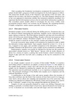
Room Lighting—Physical Architecture Entity Relationships After some analysis we develop a physical
representation or physical system architecture of the ROOM LIGHTING SYSTEM. As indicated by Figure
8.4, the system consists of the following physical entities: a POWER SOURCE, WIRE 1, WIRE 2, LIGHT
SWITCH, a BUILDING STRUCTURE, a PERSON, and a LIGHT RECEPTACLE containing a LIGHT
BULB. The solid black lines represent electrical interfaces; the dashed lines represent mechanical interfaces.
In physical terms, the BUILDING STRUCTURE provides mechanical support for the LIGHT SWITCH,
WIRE 1, WIRE 2, and LIGHT FIXTURE that holds the LIGHT BULB.
When the PERSON (physical entity) places the LIGHT SWITCH (physical entity) in the ON position,
AC current (physical entity) flows from the POWER SOURCE (physical entity) through WIRE 1 (physical
entity) to the LIGHT SWITCH (physical entity). The AC current (physical entity) flows from the LIGHT
SWITCH (physical entity) through WIRE 2 (physical entity) to the LIGHT RECEPTACLE (physical entity)
and into the LIGHT BULB. Visible light is then transmitted to the PERSON until the LIGHT SWITCH is
placed in the OFF position, the LIGHT BULB burns out, or the POWER SOURCE is disconnected.
Logical and Physical Architecture Approach
The partitioning and sequencing of these discussions provides a fundamental portion of the method-
ology for developing systems, products, or services. If you observe and analyze human behavior,
you will discover that humans characteristically have difficulty deciding WHAT decisions to make
and the strategic steps required to make those decisions. We desire lots of information but are often
unable to synthesize all of the data at the individual or team levels to arrive at an encompassing,
multi-level design solution in a single decision. As a result, the ramifications of the decision-making
process increases exponentially with the size and complexity of the system.
Given this characteristic, humans need to incrementally progress down a decision path from
simple, high-level decisions to lower level detail decisions based on the higher level decisions. The
flow from logical to physical entity relationships enables us to incrementally decompose com-
plexity. Illustrations enable us to progress from simply acknowledging the existence of a relation-
ship to detailed decisions regarding HOW the logical relationship can be physically implemented.
8.4 Understanding System Element Entity Relationships 73
Simpo PDF Merge and Split Unregistered Version -
As summarized in Figure 8.4, we evolve the logical architecture representation of the Room Light-
ing System from the abstract to the detailed physical architecture representation.
This point is important. It provides the basis for a later discussion when we introduce the
concept of the system solution domains in Part II. The domain solutions include: 1) a Requirements
Domain Solution, 2) an Operational Domain Solution, 3) a Behavioral Domain Solution, and 4) a
Physical Domain Solution.
8.5 GUIDING PRINCIPLES
In summary, the preceding discussions provide the basis with which to establish the guiding prin-
ciples that govern the architecture of systems.
Principle 8.1 System interact with external entities in their OPERATING ENVIRONMENT and
themselves.
Principle 8.2 Every system serves at the pleasure of higher order, human and natural systems
that exercise authority over the system and its operation.
Principle 8.3 Every system is part of a larger system of systems (SoS).
8.6 SUMMARY
Our discussion in this chapter introduced the fundamental concepts that form the basis for the system archi-
tecture. We introduced the concepts of the OPERATING ENVIRONMENT, SYSTEM OF INTEREST (SOI),
74 Chapter 8 The Architecture of Systems
Logical
Representation
Logical Entity Relationship
(Association)
Light
Receptacle
Light
Switc
h
Building Structure
Wire
#1
Power
Source
Light
Bulb
Light
Source
Light
Source
·
Illumination
Physical
Representation
Where:
= Electrical Rela
tionship
= Mechanical Rela
tionship
Wire
#2
Figure 8.4 Logical-Physical Representations
Simpo PDF Merge and Split Unregistered Version -
MISSION SYSTEM, and SUPPORT SYSTEM, and their interactions. We also decomposed each of these enti-
ties into classes or sets of systems elements.
The next chapter on system architecture levels of abstraction and semantics complements the discussion
of this chapter by introducing the way system elements expand into lower level abstractions. In the two sub-
sequent chapters we will discuss the SYSTEM OF INTEREST (SOI) architecture and the OPERATING
ENVIRONMENT architecture, and identify system elements within their respective abstractions and describe
those system elements in terms of the SOI and OPERATING ENVIRONMENT architectures.
GENERAL EXERCISES
1. Answer each of the What You Should Learn from This Chapter questions identified in the Introduction.
2. Refer to the list of systems identified in Chapter 2. Based on a selection from the preceding chapter’s
General Exercises or a new system selection, apply your knowledge derived from this chapter’s topical
discussions.
(a) Identify and bound the SOI’s OPERATING ENVIRONMENT
(b) Identify and bound the HIGHER ORDER SYSTEMS, PHYSICAL SYSTEMS ENVIRONMENT,
MISSION SYSTEM, and SUPPORT SYSTEM
ORGANIZATIONAL CENTRIC EXERCISES
1. Contact a system development program and investigate how their SOI interfaces with HIGHER ORDER
SYSTEMS, PHYSICAL SYSTEMS ENVIRONMENT, and SUPPORT SYSTEM. How are these elements
addressed in their system architecture diagrams? Report on your findings and observations.
REFERENCES
Additional Reading 75
Kossiakoff, Alexander, and Sweet, William N. 2003.
Systems Engineering Principles and Practice. New York:
Wiley-InterScience.
DoD 5000.59-M. 1998. DoD Modeling and Simulation
(M&S) Glossary Washington, DC: Department of
Defense.
ADDITIONAL READING
FM 770-78. 1979. System Engineering Field Manual. Washington, DC: Headquarters—Department of the Army.
Simpo PDF Merge and Split Unregistered Version -
Chapter 9
System Levels of Abstraction
and Semantics
9.1 INTRODUCTION
Every natural and human-made system is part of a HIGHER ORDER SYSTEM. The universe, for
example, can be viewed as a hierarchy of systems. Any system within that hierarchy is composed
of lower level systems. As such, we refer to it as a system of systems (SoS). Systems within the
hierarchy range from infinitely large, complex systems that exceed human comprehension and
knowledge down to the smallest instance of physical matter.
When humans, especially system analysts and SEs, attempt to communicate about systems
within the hierarchy of systems, the context of their viewpoint and semantics becomes a critical
communications issue. Despite the breadth of the English language in terms of words, those appli-
cable to the engineering of systems are finitely limited. Thus, when we attempt to apply a limited
set of semantics to large numbers of system levels, confusion ultimately results.
A common comment that echoes throughout engineering development organizations is Whose
system are you referring to? The question surfaces during conversations among Users, the Acquirer,
and System Developers. Engineering organizations grapple with trying to understand the context
of each person’s semantics and viewpoint of the system. The problem is exacerbated by a mixture
of SEs with varying degrees of semantics knowledge derived from: 1) on the job training (OJT),
2) personal study, 3) brochureware, and 4) formal training.
This section introduces the concept of system levels of abstraction that form the semantics
frame of reference used in this text. We define the context of each level of abstraction. Given that
system size and complexity vary from system to system, we describe how to tailor these levels to
your SYSTEM OF INTEREST (SOI). We conclude with some guidelines that govern system
decomposition and integration.
What You Should Learn from This Chapter
• What is an abstraction?
• For a six-level system, what are its levels of abstraction?
• How do you tailor the levels of abstraction to fit your system?
• Describe the scope and boundaries of a Level 0 or Tier 0 System?
• Describe the scope and entity relationships of a Level 1 or Tier 1 System?
• Describe the scope and entity relationships of a Level 2 or Tier 2 System?
System Analysis, Design, and Development, by Charles S. Wasson
Copyright © 2006 by John Wiley & Sons, Inc.
76
Simpo PDF Merge and Split Unregistered Version -
9.2 Establishing a Semantics Frame of Reference 77
• Describe the scope and entity relationships of a Level 3 or Tier 3 System?
• Describe the scope and entity relationships of a Level 4 or Tier 4 System?
• Describe the scope and entity relationships of a Level 5 or Tier 5 System?
• Describe the scope and entity relationships of a Level 6 or Tier 6 System?
• Describe the scope and entity relationships of a Level 7 or Tier 7 System?
• For an eight-level system, identify entity relationships between the various levels of
abstraction
• For an eight-level system, identify the entity relationships for system integration.
Definitions of Key Terms
• Product Structure The hierarchical structure of a physical system that represents decom-
positional relationships of physical entities. A top assembly drawing, specification tree, and
a bill of materials (BOM) are primary documents for describing a SYSTEM’s product
structure.
9.2 ESTABLISHING A SEMANTICS FRAME OF REFERENCE
One of your first tasks as a system analyst or SE is to establish a semantics frame of reference for
your SYSTEM OF INTEREST (SOI). When most people refer to systems, they communicate about
a system from their own observer’s frame of reference of everyday work tasks. When you listen to
communications between Users, the Acquirer, and System Developers, you soon discover that one
person’s SYSTEM equates to another person’s SUBSYSTEM, and so forth.
The System Context and Integration Points
When a system is specified and procured, one of the key issues is to understand the SYSTEM OF
INTEREST (SOI) or deliverable system’s context within the User’s OPERATING ENVIRON-
MENT. From a hierarchical system of systems (SoS) context, a System Developer’s contract deliv-
erable system is an entity within the User’s HIGHER ORDER SYSTEM abstraction. We refer to
the location within the HIGHER ORDER SYSTEM where the deliverable system is integrated as
its Integration Point (IP).
Who Is the System’s User?
Part of the challenge in defining the SYSTEM OF INTEREST (SOI) is identifying the User(s).
Some systems have both direct and indirect Users. Consider the following example:
EXAMPLE 9.1
A computer system may have several Users. These include:
1. The day-to-day operator of the computer system.
2. Maintenance personnel.
3. Personnel who receive work products generated by the computer system.
4. Trainers who provide hands-on instruction to the operators.
5. Electronic mail recipients.
So, when you say you are developing a system for the “User,” to which user are you referring?
Simpo PDF Merge and Split Unregistered Version -
Solving the Semantics Communication Problem
One of the ways to alleviate this problem is to establish a standard set of semantics that enable SEs
from all disciplines to communicate intelligibly using a common contextual language. We need to
establish a standard semantics convention. Once the convention is established, update the appro-
priate command media—meaning the organizational policies and procedures for use in training
organizational personnel.
9.3 UNDERSTANDING SYSTEM LEVELS OF ABSTRACTION
When we address the deliverable system context, we need a standard way of communicating the
embedded levels of abstraction. Since all systems are hierarchical, the User’s system may be a sup-
porting element of HIGHER ORDER SYSTEM. Given the large number of direct and indirect
Users of the system, how can we establish a simple method of communicating these levels of
abstraction? First, let’s define the term:
Author’s Note 9.1 On the surface, you may view the discussion in this section as academic
and esoteric. The reality is you, your customer (the User, Acquirer, etc.), and vendors must reach
a common consensus as to WHAT IS and WHAT IS NOT part of the SOI or deliverable system.
Does your contract or agreement explicitly delineate boundaries of the deliverable system? Ulti-
mately, when the system is verified and validated, you do not want any contract conflicts as to
WHAT IS or IS NOT included in the deliverable system.
In the contracts world, objective evidence such as a Statement of Objectives (SOOs), System
Performance Specification (SPS), Contract Work Breakdown Structures (CWBSs), and Terms and
Conditions (Ts&Cs) serve as mechanisms for documenting the understanding between both parties
regarding the system’s boundaries and work to be accomplished relative to those boundaries. As
such, they provide the frame of reference for settling programmatic and technical issues. In general,
undocumented intentions and assumptions about a system’s boundaries are unacceptable.
How the term abstraction applies to systems is illustrated in Figure 9.1. Beginning in the upper
left corner, a system, product, or service consists of an initial set of loosely coupled entities such
as ideas, objectives, concepts, and parts (i.e., items A through N).
If we analyze these entities or objects, we may determine that various groupings may share a
common set of objectives, characteristics, outcomes, etc. as illustrated in the lower left portion of
the figure. We identify several groupings of items:
1. Entity 10 consists of Entities A and E.
2. Entity 20 consists of Entities C, F, and I.
3. Entity 30 consists of Entities D, J, H, and M.
4. Entity 40 consists of Entities B, K, L, N, and O.
Each entity represents a class of object or abstraction. Abstractions or classes of objects are actu-
ally hierarchical groupings that suppress lower level details as illustrated by the right side of the
Figure 9.1. Here we have a structure that represents the hierarchical structure, or taxonomy, of a
system and each of its levels of abstraction.
The concept of generic levels of abstraction is useful information for simple systems. However,
large, complex systems involve multiple levels of detail or abstraction. Where this is the case, How
do system analysts and SEs delineate one level of abstraction from another? They do this by estab-
78
Chapter 9 System Levels of Abstraction and Semantics
Simpo PDF Merge and Split Unregistered Version -
9.3 Understanding System Levels of Abstraction 79
lishing an observer’s frame of reference convention. In a contractual context, the contract estab-
lishes the basis.
Establishing a Frame of Reference Convention
Some organizations establish a contextual frame of reference convention for a system to facilitate
communications about specific entities within the system. The intent is to designate a reference
point for the deliverable system. One example convention employs Level 0, Level 1, Level 2, and
so forth semantics as depicted in Figure 9.2. Another convention employs Tier 0, Tier 1, and so
forth semantics. However, Levels or Tiers 0 through X are simply identifiers that need more explicit
nomenclature labels. Table 9.1 provides an example nomenclature naming convention and a brief,
scoping definition.
The key point of this discussion is for you and your colleagues to establish a semantics con-
vention (Level 0/Tier 0, Level 1/Tier 1, etc.) that enables the team to communicate with a common
frame of reference relative to the User’s system—i.e. Level 0 or Tier 0. Based on an understand-
ing of the system levels of abstraction, let’s explore how we define and depict these graphically.
Relating System Levels of Abstraction and Semantics to
System Architecture
The preceding discussion describes each level and entity in terms of its hierarchical and peer
level entity relationships. These relationships provide the basic framework for defining the system
logical and physical architectures discussed later in Part II on System Design and Development
Practices.
Initial Set of Entities
Level of
Abstraction
Level of
Abstraction
System
Entity 10 Entity 20 Entity 30
A
E
F
C
I
J H
D M
B K
L
O
N
Entity 40
A
E
C
F
I
D
J
H
M
B
K
N
O
L
Entity
10
Entity
30
Entity
20
Entity
40
Level of
Abstraction
Hierarchical Levels of Abstraction
M
AC
LN
JH
G
D
F
IBK
E
Abstract via Defined Criteria
Figure 9.1 Definition of Abstraction
Simpo PDF Merge and Split Unregistered Version -
80 Chapter 9 System Levels of Abstraction and Semantics
Tailoring Levels of Abstraction for Your System’s Application
The preceding discussion also introduced a set of semantics for application to large, complex
systems. You and your organization may or may not have an eight-level system. Tailor the number
of system levels of abstraction to match your system’s application.
To illustrate this point, Figure 9.3 presents a tailored application of the standard system levels.
The left side of the figure represents the standard system levels; the right side represents an orga-
nization’s tailoring of the standard system levels. In this case the organization has adopted the fol-
lowing semantics: User system, SYSTEM, SUBSYSTEM, ASSEMBLY, and PART levels. As a
result reference level numbers. (Level 1, Level 2, etc.) have been sequentially applied to match the
tailoring.
9.4 SYSTEM DECOMPOSITION AND INTEGRATION
DESIGN GUIDELINES
System structures are viewed from two SE perspectives:
1. Analytically, as a top-down, hierarchical decomposition or expansion.
2. Physically, as bottom-up, vertically integrated sets of entities.
System composition entity relationships (ERs) enable us to analytically decompose hierarchical
systems into manageable design levels of complexity. Figure 9.4 provides a framework for the rules
stated in Table 9.2.
USER’s System
Higher Order System
Level 0 or Tier 0
System
Higher Levels
SYSTEM Level
SEGMENTS
SUBSYSTEMS
ASSEMBLIES
SUBASSEMBLIES
PARTS
PRODUCTS
Level of Abstraction
Lower Levels
Level 3 or Tier 3
Systems
Level 4 or Tier 4
Systems
Level 5 or Tier 5
Systems
Level 6 or Tier 6
Systems
Level 7 or Tier 7
Other
Organizational
Systems
Level 1 or Tier 1
Systems
Level 2 or Tier 2
Systems
Your
System
Figure 9.2 System Levels of Abstraction
Simpo PDF Merge and Split Unregistered Version -
9.4 System Decomposition and Integration Design Guidelines 81
Table 9.1 System levels of abstraction descriptions
Level Nomenclature Scoping Definition
or Tier (Optional)
0 User’s A level of abstraction that represents the User’s business environment with
SYSTEM Level your SYTEM OF INTEREST (SOI) as an embedded element. We refer to
this as the Level 0 or Tier 0 system.
1 SYSTEM Level A level of abstraction that describes on the top-level representation of your
SOI from the organization’s (observer’s) frame of reference.
Architectural representations (i.e., an architectural block diagram, ABD)
of the SYSTEM level include the SOI boundaries, interfaces to external
systems in the operating environment, and embedded SEGMENT level
entities (if applicable) or PRODUCT level entities and their interfaces. This
level of abstraction is referred to as a Level 1 or Tier 1 system.
2 SEGMENT Level Refers to system entities at the first level of decomposition below the
(optional) SYSTEM level. Each instance of a SEGMENT level entity is referred to as
a Level 2 or Tier 2 system.
An architectural representation of a SEGMENT level entity includes:
1. Level 3 or Tier 3 PRODUCTS and lower level entities.
2. Their internal PRODUCT level relationships.
3. The SEGMENT’s relationships with external entities within the SYSTEM
(i.e., with other SEGMENTS) and external systems beyond the
SYSTEM’s boundaries, as applicable. Consider the following example:
EXAMPLE 9.2 A communications SYSTEM might consist of land-based,
sea-based, air-based, and space-based SEGMENTS.
3 PRODUCT Level Refers to system entities at the first level of decomposition below the
(optional) SEGMENT level. Each instance of a PRODUCT Level entity is referred to
as a Level 3 or Tier 3 system.
An architectural representation of a PRODUCT level entity includes:
1. Level 4 or Tier 4 SUBSYSTEMS and lower level entities.
2. Their internal SUBSYSTEM level entity relationships.
3. The PRODUCT’s relationships with external entities within the SYSTEM
(i.e., with other PRODUCTS) and external systems beyond the
SYSTEM’s boundaries, as applicable.
4 SUBSYSTEM Refers to system entities at the first level of decomposition below the
Level PRODUCT Level. Each instance of a SUBSYSTEM level entity is referred
to as a Level 4 or Tier 4 system.
An architectural representation of a SUBSYSTEM level entity includes:
1. Level 5 or Tier 5 ASSEMBLIES and lower level entities.
2. Their internal ASSEMBLY level entity relationships.
3. The SUBSYSTEM’s relationships with external entities within the
SYSTEM (i.e., with other SUBSYSTEMS) or external systems beyond
the SYSTEM’s boundaries, as applicable.
5 ASSEMBLY Refers to system entities at the first level of decomposition below the
Level SUBSYSTEM level. Each instance of an ASSEMBLY level entity is
referred to as a Level 5 or Tier 5 system.
An architectural representation of an ASSEMBLY level entity includes:
(continued)
Simpo PDF Merge and Split Unregistered Version -
82 Chapter 9 System Levels of Abstraction and Semantics
Author’s Note 9.3 Hierarchical decomposition follows the same rules as outlining a report.
Avoid having a single item subordinated to a higher level item. Good design practice suggests that
you should always have at least two or more entities at a subordinated level. In the case of systems
this does not mean that the subordinate entities must be at the same level of abstraction.
For example, the Bill of Materials (BOM)—meaning a parts list—for a top level assembly
within a product structure may consist of at least one or more SUBSYSTEMS, one or more ASSEM-
BLIES, and at least one or more PARTS kit (e.g., nuts and bolts). If we depict the BOM as an inden-
tured list, the PARTS kit used to mechanically and electrically connect the SUBSYSTEMS and
ASSEMBLIES into an INTEGRATED SYSTEM may be at the same level of abstraction as the SUB-
SYSTEMS and ASSEMBLIES.
As a final note, this text treats entities at any level of abstraction as components of the system.
9.5 SUMMARY
Our discussion in this chapter has introduced the hierarchical concept of system levels of abstraction and
semantics. This hierarchical framework enables SEs to standardize analysis and communications about their
SYSTEM OF INTEREST (SOI). The intent of a semantics convention is to synchronize members of a System
Developer’s team, the Acquirer, and the User on a common set of terms to use in communicating complex
hierarchies.
Table 9.1 continued
Level Nomenclature Scoping Definition
or Tier (Optional)
1. Level 6 or Tier 6 COMPONENTS and lower level entities.
2. Their internal SUBASSEMBLY level entity relationships.
3. The ASSEMBLY’s relationships with external entities within the
SYSTEM (i.e., with other ASSEMBLIES) or external systems beyond
the SYSTEM’s boundaries, as applicable.
6 SUBASSEMBLY Refers to system entities at the first level of decomposition below the
Level ASSEMBLY level. Each instance of a SUBASSEMBLY level entity is
referred to as a Level 6 or Tier 6 system.
Architectural representation of a SUBASSEMBLY Level entity includes:
1. Level 7 or Tier 7 PARTS.
2. Their internal PART level entity relationships.
3. The SUBASSEMBLY’s relationships with external entities within the
SYSTEM (i.e., with other SUBASSEMBLIES) or external systems
beyond the SYSTEM’s boundaries, as applicable.
7 PART Level Refers to the lowest level decompositional element of a system.
An architectural representation of a PART includes form factor envelope
drawings, schematics, and models.
Author’s Note 9.2 Engineering drawings, which are produced at all
system levels of abstraction, consist of two basic types:
1. Dimensional drawings or schematics for internally developed or
externally procured and modified internally items.
2. Source control drawings that bound part parameters and characteristics
for externally procured parts.
For software systems, the PART level equates to a source line of code
(SLOC).
Simpo PDF Merge and Split Unregistered Version -
9.5 Summary 83
Standard System Levels Tailored System Levels
ASSEMBLY Level
SYSTEM Level
(System of Interest)
SEGMENT Level
SUBSYSTEM Level
COMPONENT Level
PART Level
PRODUCT Level
Level 0
Level 1
Level 2
Level 3
Level 4
Level 5
Level 6
End User’s System
Level 7
ASSEMBLY Level
SYSTEM Level
(System of Interest)
SEGMENT Level
SUBSYSTEM Level
COMPONENT Level
PART Level
PRODUCT Level
Level 0
Level 1
Level 2
Level 3
Level
4
End User’s System
Tailored
Figure 9.3 System Levels of Abstraction and Tailoring Example
System Hierarchical Decomposition
System Integration
SYSTEM
SYSTEM
SUBSYSTEM
S
SUBSYSTEMS
ASSEMBLIES
ASSEMBLIES
SUBASSEMBLIES
SUBASSEMBLIES
PART
S
PARTS
PRODUCT
S
PRODUCTS
SEGMENTS
SEGMENTS
= Consists of
Where:
= May or may no
t
consist of
= Composition
Figure 9.4 System Decomposition/Integration Rules
Simpo PDF Merge and Split Unregistered Version -
84 Chapter 9 System Levels of Abstraction and Semantics
As part of our discussion, we provided a mechanism for System Developers that allows them to bench-
mark their system in the context of the User’s larger system. This was accomplished using the Level 0 or Tier
0 convention. This convention, or whatever you and your team decide to use, must answer the central ques-
tion, Whose system are you referring to?
GENERAL EXERCISES
1. Answer each of the What You Should Learn from This Chapter questions identified in the Introduction.
2. Refer to the list of systems identified in Chapter 2. Based on a selection from the preceding chapter’s
General Exercises or a new selection, apply your knowledge derived from this chapter’s topical
discussions.
(a) Equate system levels of abstraction to multi-level entities of the physical system selected.
(b) Develop an entity relationships diagram that identifies physical entity relationships.
Table 9.2 System entity decomposition and integration rules
Level or Tier Entity Entity Decomposition/Integration rules
0 User Level The User’s SYSTEM is bounded by its organizational mission and
consists of the system element assets required to accomplish that
mission within its OPERATING ENVIRONMENT.
1 SYSTEM Level Each instance of a SYSTEM consists of at least two or more
instances of SEGMENT, PRODUCT, SUBSYSTEM, ASSEMBLY,
SUBASSEMBLY, or PART level entities or combinations thereof.
2 SEGMENT Level If the SEGMENT level of abstraction or class is applicable, each
SEGMENT level entity consists of at least two or more instances of
PRODUCT, SUBSYSTEM, ASSEMBLY, SUBASSEMBLY, or PART
level entities or combinations thereof.
3 PRODUCT If the PRODUCT level of abstraction or class is applicable, each
Level instance of a PRODUCT level entity consists of at least two or
more instances of SUBSYSTEM, ASSEMBLY, SUBASSEMBLY, or
PART level entities or combinations thereof.
4 SUBSYSTEM If the SUBSYSTEM level of abstraction or class is applicable, each
Level instance of a SUBSYSTEM level entity consists of at least two or
more instances of ASSEMBLY, SUBASSEMBLY, or PART level
entities or combinations thereof.
5 ASSEMBLY If the ASSEMBLY level of abstraction or class is applicable, each
Level instance of an ASSEMBLY level entity consists of at least two or
more instances of SUBASSEMBLY or PART level entities or
combinations thereof.
6 SUBASSEMBLY If the SUBASSEMBLY level of abstraction or class is applicable,
Level each instance of a SUBASSEMBLY level entity must consist of at
least two or more instances of PART level entities.
7 PART The PART level is the lowest decompositional element of a system.
Level
Note: For hierarchical decomposition, read the table top-down from Level 0 to Level 7 order; for integration, read the
table bottom-up in reverse order—from Level 7 to Level 0.
Simpo PDF Merge and Split Unregistered Version -
ORGANIZATION CENTRIC EXERCISES
1. Contact a program organization and investigate what levels of abstraction and semantics are used.
2. Research your organization’s command media for guidance in identifying levels of abstraction.
(a) What guidance, if any, is provided?
(b) How does each program establish its own guidance?
Organization Centric Exercises
85
Simpo PDF Merge and Split Unregistered Version -
Chapter 10
The System of Interest Architecture
10.1 INTRODUCTION
The central focal point for the development of any system is the SYSTEM OF INTEREST (SOI)
consisting of the MISSION SYSTEM(s) and its SUPPORT SYSTEM(s). Since every system within
the supply chain performs two roles—MISSION SYSTEM and SUPPORT SYSTEM—analysis
reveals that each role consists of seven classes of system elements that form its architectural
framework.
This section introduces the concept of SOI system elements. We identify the system elements
and describe the System Element Architecture that forms the analytical basis for analyzing systems
and their interactions with their OPERATING ENVIRONMENT. We describe the scope and bound
the contents of each element.
What You Should Learn from This Chapter
• What is an SOI?
• What are the key elements of an SOI?
• Graphically depict the generalized system architecture of an SOI including its external
interfaces.
• What are the key elements of a MISSION SYSTEM?
• Graphically depict the generalized system architecture of a MISSION SYSTEM including its
external interfaces.
• What is the scope of the PERSONNEL, EQUIPMENT, MISSION RESOURCES, PROCE-
DURAL DATA, FACILITIES, and SYSTEM RESPONSES elements?
• What are the key elements of the EQUIPMENT Element?
• Why is the SOFTWARE Element separate from the EQUIPMENT Element?
• What are the key elements of the SUPPORT SYSTEM?
• Graphically depict the generalized system architecture of a SUPPORT SYSTEM including
its external interfaces.
• How does the MISSION SYSTEM architecture differ from the SUPPORT SYSTEM
architecture?
• What are the key elements of a SUPPORT SYSTEM’s EQUIPMENT Element?
• What are CSE and PSE?
System Analysis, Design, and Development, by Charles S. Wasson
Copyright © 2006 by John Wiley & Sons, Inc.
86
Simpo PDF Merge and Split Unregistered Version -
10.2 The System Element Architecture Construct 87
10.2 THE SYSTEM ELEMENT ARCHITECTURE CONSTRUCT
Every human-made system consists of a generalized framework we refer to as the System Element
Architecture (SEA). The SEA represents a logical arrangement of system elements that serve as gen-
eralized construct or template for systems design and analysis. Figure 10.1 provides a graphical
representation of the SEA. To promote readability and simplicity in the figure, the OPERATING
ENVIRONMENT is abstracted as a single entity.
Every system performs MISSION SYSTEM and SUPPORT SYSTEM roles as part of its
tasking from HIGHER ORDER SYSTEMS. Regardless of the system role, each system consists
of combinations of system elements with specific system and mission objectives.
Mission System and Support System Compositional Elements
Each MISSION SYSTEM and SUPPORT SYSTEM consists of a unique set of integrated system
elements that enable the system to accomplish its mission and objectives. The mission/support
system elements are PERSONNEL, EQUIPMENT, SOFTWARE, MISSION RESOURCES,
PROCEDURAL DATA, and SYSTEM RESPONSES. Table 10.1 relates each of these elements to
the MISSION SYSTEM and SUPPORT SYSTEM roles.
Author’s Note 10.1 MISSION SYSTEMS such as aircraft, vehicles, etc. do not have a FACIL-
ITIES Element. In contrast, a home or an office owned by the occupants, as a MISSION SYSTEM,
does have a FACILITIES Element.
SOI Architectural System Elements
The System Element Architecture consists of analytical abstractions that represent the SYSTEM
OF INTEREST (SOI) interactions with its OPERATING ENVIRONMENT. The SOI consists of
the MISSION SYSTEM as an abstraction with interfaces to the SUPPORT SYSTEM.
1
SUPPORT
SYSTEM(s)
• Personnel
• Equipment
• Mission Resources
• Procedural Data
• Facilities
• System
Responses
SUPPORT
SYSTEM(s)
• Personnel
• Equipment
• Mission Resources
• Procedural Data
• Facilities
• System
Responses
Procedural
Data
Elemen
t
Procedural
Data
Elemen
t
Equipment
Element
• Hardware
• Software
•M
anuals
Equipment
Element
• Hardware
• Software
• Manuals
Personnel
Elemen
t
Personnel
Element
Mission
Resources
Elemen
t
Mission
Resources
Elemen
t
MISSION SYSTEM(s)
System
Responses
• Products
• By-Products
• Services
• Behavio
r
System
Responses
• Products
• By-Products
• Services
• Behavio
r
OPERATING ENVIRONMENT
OPERATING ENVIRONMENT
= Physical Interface
= Logical Interfac
e
1417
13
7
12
4
8
10
9
2
6
5
11
3
System of Interest
(SOI
)
1
16 15
For simplicity, the SOFTWARE Element is placed under the
EQUIPMENT Element. Some have a separate SOFTWARE Element.
Figure 10.1 The System of Interest (SOI) Architecture and its System Elements
Simpo PDF Merge and Split Unregistered Version -
88 Chapter 10 The System of Interest Architecture
EXAMPLE 10.1
A new automobile serves a MISSION SYSTEM (role) for the User. The transporter vehicle that delivers the
new car to the dealership where the car is purchased serves as a SUPPORT SYSTEM (role) to the MISSION
SYSTEM. To the organization that owns and operates the transporter, the transporter vehicle performs a
MISSION SYSTEM role.
The PERSONNEL System Element
The PERSONNEL element 1) consists of all human roles required to perform the system mission
operations in accordance with safe operating practices and procedures, and 2) has overall account-
ability for accomplishing mission objectives assigned by HIGHER ORDER SYSTEMS.
• MISSION SYSTEM PERSONNEL Roles Include all personnel directly required to
operate the MISSION SYSTEM and accomplish its objectives. In general, these personnel
are typically referred to as System Operators.
• SUPPORT SYSTEM PERSONNEL Roles Include personnel who support the MISSION
SYSTEM through maintenance, supply support, training, publications, security, and other
activities.
The EQUIPMENT System Element
The EQUIPMENT system element consists of any physical, multi-level, electromechanical optical
device that represents an integration of the HARDWARE Element and the SOFTWARE Element,
if applicable. This integration of elements is:
1. Developed and/or procured to satisfy a system entity capability and performance
requirement.
2. Used to operate and maintain the system.
3. Used to generate or store energy required by the system.
4. Used to dispose of a system.
The ultimate success of the MISSION SYSTEM requires that the EQUIPMENT Element be oper-
ationally available and fully capable of supporting the system missions and the safety of its PER-
SONNEL to ensure a level of success. As a result specialty engineering (reliability, availability,
maintainability, vulnerability, survivability, safety, human factors, etc.) becomes a key focus of the
EQUIPMENT Element. Depending on the application, EQUIPMENT may be fixed, transportable,
or mobile.
Table 10.1 System elements common to MISSION SYSTEM and SUPPORT SYSTEM roles
System Element MISSION SYSTEM Role SUPPORT SYSTEM Role
PERSONNEL • •
EQUIPMENT • •
MISSION RESOURCES • •
PROCEDURAL DATA • •
SYSTEM RESPONSES • •
FACILITIES •
Simpo PDF Merge and Split Unregistered Version -
10.2 The System Element Architecture Construct 89
The HARDWARE System Element
The Hardware Element represents the integrated set of multi-level, physical components—mechan-
ical, electrical/electronic, or optical less software—configured in accordance with the system archi-
tecture. Whereas the Hardware Element is common to both the MISSION SYSTEM and the
SUPPORT SYSTEM, there are difference in the classes of components. MISSION SYSTEM hard-
ware components are physically integrated to provide the capabilities required to accomplish
mission objectives. SUPPORT SYSTEM hardware components consist of tools required to main-
tain and support the MISSION SYSTEM. These tools are categorized as: 1) Common Support
Equipment (CSE) and 2) Peculiar Support Equipment (PSE).
Common Support EQUIPMENT (CSE). Common support equipment (CSE) consists of the
items required to support and maintain the system or portions of the system while not directly
engaged in the performance of its mission. CSE items are in the organization’s inventory for support
of other systems. CSE excludes:
• Overall planning, management and task analysis functions inherent in the work breakdown
structure element, Systems Engineering/Program Management.
• Common support equipment, presently in the inventory or commercially available, bought
by the User, not by the Acquirer.
Peculiar Support EQUIPMENT (PSE). MIL-HDBK-881 characterizes peculiar support
equipment (PSE) as follows:
. . . the design, development, and production of those deliverable items and associated software
required to support and maintain the system or portions of the system while the system is not directly
engaged in the performance of its mission, and which are not common support equipment (CSE).
(Source: Mil-HDBK-881, Appendix H, para. 3.6).
PSE includes:
• Vehicles, equipment, tools, etc., used to fuel, service, transport, hoist, repair, overhaul, assemble,
disassemble, test, inspect, or otherwise maintain mission equipment.
• Any production of duplicate or modified factory test or tooling equipment delivered to the (Acquirer)
for use in maintaining the system. (Factory test and tooling equipment initially used by the contractor
in the production process but subsequently delivered to the (Acquirer) will be included as cost of the
item produced.)
• Any additional equipment or software required to maintain or modify the software portions of the
system.
(Source: Mil-HDBK-881, Appendix H, para. 3.6).
CSE and PCE Components
Common support equipment (CSE) and peculiar support equipment (PSE) each employ two cate-
gories of equipment that are common to both types: 1) test, measurement, and diagnostics equip-
ment (TMDE) and 2) support and handling equipment.
Test, Measurement, and Diagnostics Equipment (TMDE). MIL-HDBK-881 characterizes
test, measurement, and diagnostics equipment (TMDE) as follows:
. . . consists of the peculiar or unique testing and measurement equipment which allows an operator
or maintenance function to evaluate operational conditions of a system or equipment by performing
Simpo PDF Merge and Split Unregistered Version -
specific diagnostics, screening or quality assurance effort at an organizational, intermediate, or depot
level of equipment support.
TMDE, for example, includes:
• Test measurement and diagnostic equipment, precision measuring equipment, automatic test equipment,
manual test equipment, automatic test systems, test program sets, appropriate interconnect devices,
automated load modules, taps, and related software, firmware and support hardware (power supply
equipment, etc.) used at all levels of maintenance.
• Packages which enable line or shop replaceable units, printed circuit boards, or similar items to be
diagnosed using automatic test equipment.
(Source: Mil-HDBK-881, Appendix H, para. 3.7.1)
Support and Handling EQUIPMENT. Support and handling EQUIPMENT consists of the
deliverable tools and handling equipment used for support of the MISSION SYSTEM. This includes
“. . . ground support equipment (GSE), vehicular support equipment, powered support equipment,
unpowered support equipment, munitions material handling equipment, materiel-handling
equipment, and software support equipment (hardware and software).” (Source: Mil-HDBK-881,
Appendix H, para. 3.7.2)
The SOFTWARE System Element
The SOFTWARE element consists of all software code (source, object, etc.) and documentation
required for installation, execution, and maintenance of the EQUIPMENT Element. You may ask
why some organizations separate the SOFTWARE Element from its EQUIPMENT element. There
are several reasons:
1. EQUIPMENT and SOFTWARE may be developed separately or procured from different
vendors.
2. SOFTWARE may provide the flexibility to alter system capabilities and performance
(decision-making, behavior, etc.) without having to physically modify the EQUIPMENT,
assuming the current EQUIPMENT design is adequate.
Author’s Note 10.2 The EQUIPMENT element consists of integrated HARDWARE and SOFT-
WARE as subordinated and supporting elements. Engineers become prematurely focused with
hardware and software details long before higher level SOI decisions have been made—namely
EQUIPMENT requirements. EQUIPMENT decisions lead to lower level HARDWARE and SOFT-
WARE use cases and decisions. These decisions subsequently lead to the question: What capabil-
ities should be implemented in HARDWARE versus those implemented in SOFTWARE?
SE logic says that HARDWARE and SOFTWARE may be separately procurable items. The under-
lying philosophy is SOFTWARE, as a system element, should be isolated to accommodate modi-
fication without necessarily having to modify the HARDWARE.
Application specific SOFTWARE can be procured as a separate item, regardless of its posi-
tion within the system structure as long as a controlled software requirements specification (SRS)
exists for the item’s development. As new versions of application specific SOFTWARE are released,
the User can procure the item without modifying the EQUIPMENT. There may be exceptions,
however, where SOFTWARE requirements and priorities force the User to upgrade the computer
HARDWARE capabilities and performance.
90
Chapter 10 The System of Interest Architecture
Simpo PDF Merge and Split Unregistered Version -
10.2 The System Element Architecture Construct 91
The PROCEDURAL DATA System Element
The PROCEDURAL DATA element consists of all documentation that specifies HOW to safely
operate, maintain, deploy, and store the EQUIPMENT Element. In general, the PROCEDURAL
DATA Element is based on operating procedures. Operating procedures document sequences of
PERSONNEL actions required to ensure the proper and safe operation of the system to achieve its
intended level of performance under specified operating conditions. The PROCEDURAL DATA
Element includes items such as reference manuals, operator guides, standard operating practices
and procedures (SOPPs), and checklists.
Author’s Note 10.3 Unfortunately, many people view checklists as bureaucratic nonsense,
especially for organizational processes. Remember, checklists incorporate lessons learned and best
practices that keep you out of trouble. Checklists are a state of mind—you can view them as
“forcing” you to do something or as a “reminder” to “think about what you may have overlooked.”
As a colleague notes, when landing an aircraft, if the checklist says to “place the landing gear in
the deployed and locked position,” you may want to consider putting the landing gear down before
you land! Bureaucratic or not, the consequences for a lack of compliance can be catastrophic!
The MISSION RESOURCES System Element
The MISSION RESOURCES element includes all data, consumables, and expendables required
on-board to support the system mission. This element consists of:
1. Data to enable the EQUIPMENT and the PERSONNEL Elements to successfully plan and
conduct the mission based on “informed” decisions.
2. Consumables such as fuel and water to support the EQUIPMENT and PERSONNEL Ele-
ments during the mission.
Personnel
Equipment
Procedural Data
Mission Resources
Facilities
Personnel
Equipment
Procedural
Data
Mission Resources
Facilities
System Element
System Responses
System Responses
1
8
2 3 5
9 10 127
14 16 1813
20 21 2419
26 27 2825
32 33 3431
System Element
4
11
17
35
23
30
To
From
6
15
22
29
36
Where: = entity relationships and associated capabilities
X
Figure 10.2 System Element Entity Relationships Matrix
Simpo PDF Merge and Split Unregistered Version -
3. Expendables such as personal and defensive systems and products to ensure a safe and
secure mission.
4. Recorded data for postmission performance analysis and assessment.
Let’s scope each of the four types of MISSION RESOURCES in detail.
• Mission Data Resources Consist of all real-time and non-real-time data resources such as
tactical plans, mission event timelines (METs), navigational data, weather conditions and
data, situational assessments, telecommunications, telemetry, and synchronized time that are
necessary for performing a mission with a specified level of success.
• Expendable Resources Consist of physical entities that are used and discarded, deployed,
lost, or destroyed during the course of mission operations.
• Consumable Resources Consist of physical entities that are ingested, devoured, or input into
a processor that transforms or converts the entity into energy to power the system and may
involve physical state changes.
The SYSTEM RESPONSES Element
Every natural and human-made system, as a stimulus-response mechanism, responds internally or
externally to stimuli in its OPERATING ENVIRONMENT. The responses may be explicit (reports,
communications, altered behavior, etc.) or implicit (mental thoughts, strategies, lessons learned,
behavioral patterns, etc.).
SYSTEM RESPONSES occur in a variety of forms that we characterize as behavioral pat-
terns, products, services, and by-products throughout the system’s pre-mission, mission, and post-
mission phases of operation. So, what do we mean by system behavior, products, services, and
by-products?
• System Behavior Consists of SYSTEM RESPONSES based on a plan of action or physical
stimuli and audiovisual cues such as threats or opportunities. The stimuli and cues invoke
system behavioral patterns or actions that may be categorized as aggressive, benign, defen-
sive, and everywhere in between. Behavioral actions include strategic and tactical tactics and
countermeasures.
• System Products Include any type of physical outputs, characteristics, or behavioral
responses to planned and unplanned events, external cues, or stimuli.
• System By-products Include any type of physical system output or behavioral that is not
deemed to be a system, product, or service.
• System Services Any type of physical system behavior, excluding physical products, that
assist another entity in the conduct of its mission.
Author’s Note 10.4 It is important to note here that abstracting “behavioral responses” via a
“box” called SYSTEM RESPONSES is simply an analytical convenience—not reality. Most system
element descriptions fail to recognize this box for what it is, expected outcome-based system per-
formance such as operational utility, suitability, availability, and effectiveness.
The SUPPORT SYSTEM Element
The SUPPORT SYSTEM consists of an integrated set of system elements depicted in Table 10.1
required to support the MISSION SYSTEM. The SUPPORT SYSTEM and its system elements
perform mission system support operations that consist of the following:
92
Chapter 10 The System of Interest Architecture
Simpo PDF Merge and Split Unregistered Version -
• Decision support operations
• System maintenance operations
• Manpower and personnel operations
• Supply support operations
• Training and training support operations
• Technical data operations
• Computer resources support operations
• Facilities operations
• Packaging, handling, storage, and transportation (PHST) operations
• Publications support operations
Let’s briefly describe each of these types of operations.
Decision Support Operations. Mission operations often require critical and timely decisions
based on massive amounts of information that exceed the mental capabilities of the human decision
maker. Decision support operations ensure that the decision maker always has immediate access to
the most current, processed system mission information to support an informed decision.
System Maintenance Operations. System maintenance operations include system main-
tenance support concepts and requirements for manpower and personnel; supply support; support
and test equipment; technical data; training and support; facilities; and packaging, handling, storage,
transportation; computer resources support required insightful planning. Maintenance support
operations establish support for both general system operations and mission specific operations
throughout the System O&S Phase. Examples include software maintenance concepts, pre-planned
product improvements (P
3
I), outsourcing, and transition planning.
Between operational missions, maintenance personnel normally perform corrective and pre-
ventative maintenance on the system. Maintenance activities may be conducted in the field, at a
depot or maintenance facility at some central location, or at the manufacturer’s facility.
Generally, a system may be temporarily removed from active duty during maintenance. Types
of maintenance include:
1. System upgrades, enhancements, and refinements.
2. Replenishment and refurbishment of system resources (fuel, training, etc.).
3. Diagnostic readiness tests.
4. Backup of system information for archival purposes.
Maintenance may also include investigations of mission or system anomalies through duplication
of technical problem or investigations of system health and status resulting from abnormal operat-
ing conditions before, during, or after a mission. On completion of the maintenance activities, the
system may be returned to a state of operational readiness and active duty or scheduled for system
operator or readiness training.
Manpower and Personnel Operations. Manpower and Personnel operations consist of all
personnel required to manage, operate, and support the system throughout its operational life.
Manpower and personnel considerations include in-house versus contractor tasks, skill mixes,
and human-system interfaces. When designing systems, systems engineering must factor in
considerations of the skill levels of the available personnel, training costs, labor costs of operate,
10.2 The System Element Architecture Construct 93
Simpo PDF Merge and Split Unregistered Version -
and leverage technology such as built-in diagnostics, information technology, and expert systems
to provide the best life cycle cost trade-offs—given the skill levels.
Supply Support Operations. Supply support operations ensure that all equipment and spares
required to support the primary system, system support, and test equipment and the “supply lines”
for those items are established to support pre-mission, mission, and post-mission operations. Some
organizations refer to the initial support as provisioning and follow-on requirements as routine
replenishment. A key supply support objective is to minimize the number of different PARTS and
promote standardization of parts selection and usage. Key issues to be addressed include
communication transfer media, inventory management, configuration management, storage,
security, and licensing.
Training and Training Support Operations. Training and training support operations ensure
that all personnel required to support the pre-mission, mission, and post-mission operations are
fully trained and supported. Personnel training consists of those activities required to prepare system
personnel such as operators, maintenance personnel, and other support personnel to conduct or
support pre-mission, mission, and postmission operations. Personnel must be trained with the
appropriate skills to perform their assigned mission objectives and tasks on specific equipment to
achieve the required level of performance and expected results.
Technical Data Operations. Pre-mission, mission, and post-mission operations require
accurate, precise, and timely technical data. Technical data operations support personnel and
computer equipment decision making to ensure that all decisions are made when scheduled or as
appropriate to achieve the mission objectives, level of performance, and expected results.
Computer Resources Support Operations. Many systems are highly dependent on
technology such as computer resources to provide information and processing of data to support
pre-mission, mission, and post-mission operations. Computer resources support operations include:
planning, procurement, upgrade, and maintenance support to ensure that system reliability,
availability, and maintainability (RAM) requirements will be achieved in a cost-effective manner.
Packaging, Handling, Storage, and Transportation (PHST) Operations. During system
deployment, redeployment, and storage, system support activities must provide the capability to
safely and securely transport and store the system and its components. Shipment and storage must
be accomplished to avoid damage or decomposition. PHST activities must have a clear
understanding of the environmental conditions and characteristics that pose risk to the system while
in transit as well as long-term shelf-life effects on materials.
Publications Support Operations. System maintenance and support personnel require
immediate access to the most current information regarding system and system support equipment
to ensure proper maintenance and usage. Publication support activities, sometimes referred to as
Tech Pubs, produce technical manuals, reference guides, and the like, that enable SUPPORT
SYSTEM personnel training activities, maintenance activities, and general operations in support of
pre-mission, mission, and post-mission operations.
The FACILITIES System Element
The FACILITIES element includes all the system entities required to support and sustain the
MISSION SYSTEM Elements and the SUPPORT SYSTEM Elements.
94
Chapter 10 The System of Interest Architecture
Simpo PDF Merge and Split Unregistered Version -
10.3 System Element Interactions 95
System support for pre-mission, mission, and post-mission operations requires FACILITIES to
enable operator and support PERSONNEL to accomplish their assigned mission tasks and objec-
tives in a reasonable work environment. Depending on the type of system, these FACILITIES
support the following types of tasks:
1. Plan, conduct, and control the mission.
2. Provide decision support.
3. Brief and debrief personnel.
4. Store the physical system or product between missions.
5. Configure, repair, maintain, refurbish, and replenish system capabilities and resources.
6. Analyze post-mission data.
Where practical, the FACILITIES element should provide all of the necessary and sufficient capa-
bilities and resources required to support MISSION SYSTEM and human activities during pre-
mission, mission, and post-mission operations objectives. FACILITIES may be owned, leased,
rented, or be provided on a limited one-time use agreement.
In general, people tend to think of FACILITIES as enclosures that provide shelter, warmth,
and protection. This thought process is driven by human concerns for creature comfort rather than
the mission system. Rhetorically speaking, Does an aircraft ever know that it is sitting in the
rain? No, but members of the SUPPORT SYSTEM’S PERSONNEL Element are aware of the
conditions.
Perhaps the best way to think of the FACILITY Element is to ask the question: What type of
interface is required to support the following MISSION SYSTEM Elements—namely EQUIPMENT
Element, PERSONNEL Element, MISSION DATA Element, and RESOURCES Element—during all
phases of the mission.
The FACILITIES Element fulfills a portion of the SUPPORT SYSTEM role. Depending on
the MISSION SYSTEM and its application, the FACILITIES Element may or may not be used in
that context. For example, an aircraft—which is a MISSION SYSTEM—does not require a FACIL-
ITY to perform its primary mission. However, between primary missions, FACILITIES are required
to maintain and prepare the aircraft for its next mission.
10.3 SYSTEM ELEMENT INTERACTIONS
Figure 10.1 illustrates the System Element Architecture (SEA) for a SOI. When you define your
system and identify physical instances of each system element, the next step is to characterize the
levels of interactions that occur between each interface. The Contract Work Breakdown Structure
(CWBS) should include a CWBS Dictionary that scopes and documents the physical items included
in each CWBS element such as EQUIPMENT.
One approach to ensuring system element interactions are identified and scoped is to create a
simple matrix such as the one shown in Figure 10.2. For illustration purposes, each cell of the
system element matrix represents interactions between the row and column elements. For your
system, employ such a scheme and document the interactions in a description of the system archi-
tecture. Then, baseline and release this document to promote communications among team members
developing and making system element decisions.
Simpo PDF Merge and Split Unregistered Version -