System Analysis, Design, and Development Concepts, Principles, and Practices phần 4 pdf
Bạn đang xem bản rút gọn của tài liệu. Xem và tải ngay bản đầy đủ của tài liệu tại đây (2.69 MB, 84 trang )
22.5 GUIDING PRINCIPLES
In summary, the preceding discussions provide the basis with which to establish guiding principles
that govern the implementation of a system capability.
Principle 22.1 Every operational capability has a System Capability Construct that models the
capability’s action-based operations, tasks, and external interactions.
Principle 22.2 Every operational capability requires an external trigger—a cue or a stimulus—
to initiate its outcome-based processing.
Principle 22.3 Every operational capability, as an integrated system, consists of three sequen-
tial phase-based actions:
1. Pre-mission phase—initialization.
2. Mission phase—application-based performance.
3. Post-mission phase—analysis and deactivation.
Principle 22.4 Every capability requires consideration of HOW exceptions to NORMAL and
ABNORMAL operations will be handled.
Principle 22.5 On completion of tasking, every capability should report notification of suc-
cessful completion.
22.6 SUMMARY
This chapter introduced the System Capability Construct and discussed its application to systems. Our dis-
cussion covered the construct’s operations and control flows, and equated its structure to real world examples.
We also emphasized the importance of the construct as a graphical checklist for specifying capability require-
ments statements in terms of WHAT must be accomplished and HOW WELL without specifying HOW the
requirement was to be implemented.
GENERAL EXERCISES
1. Answer each of the What You Should Learn from This Chapter questions identified in the Introduction.
2. Refer to the list of systems identified in Chapter 2. Based on a selection from the preceding chapter’s
General Exercises or a new system selection, apply your knowledge derived from this chapter’s topical
discussions. If you were the designer of a specific capability, using Figure 22.1 as a guide,
(a) Describe the set of tasks the capability should perform.
(b) How would you handle exceptions?
(c) How are outcome based results of the capability reported? In what format and media?
(d) Translate each of the capability tasks into a set of operational capability requirements.
General Exercises
239
Simpo PDF Merge and Split Unregistered Version -
ORGANIZATIONAL CENTRIC EXERCISES
1. Contact a program within your organization. Interview SEs concerning how they define and implement a
capability.
(a) How do their designers accommodate the various operations or tasks of the System Capability
Construct?
(b) Without making them aware of this chapter’s discussions or Figure 22.1, have they synthesized
this concept on their own or just unconsciously do things ad hoc based on lessons learned from
experience?
(c) Present your findings and observations.
240 Chapter 22 The Anatomy of a System Capability
Simpo PDF Merge and Split Unregistered Version -
Chapter 23
System Analysis Synthesis
Throughout Part I we sequenced through topical series of chapters that provide an analytical per-
spective into HOW to THINK about, organize, and characterize systems. These discussions provide
the foundation for Part II System Design and Development Practices, which enable us to translate
an abstract System Performance Specification (SPS) into a physical system that can be verified and
validated as meeting the User’s needs. So, HOW did Part I System Analysis Concepts provide this
foundation?
23.1 SYNTHESIZING PART I ON SYSTEM
ANALYSIS CONCEPTS
Part I concepts were embodied in several key themes that systems analysts and SEs need to under-
stand when developing a new system, product, or service.
1. WHAT are the boundary conditions and constraints imposed by the User on a
system, product, or service in terms of missions within a prescribed OPERATING
ENVIRONMENT?
2. Given the set of boundary conditions and constraints, HOW does the User envision deploy-
ing, operating, and supporting the system, product, or service to perform its missions within
specific time limitations, if applicable?
3. Given the deployment, operation, support, and time constraints planned for the system,
product, or service, WHAT is the set of outcome-based behaviors and responses required
of the system to accomplish its missions?
4. Given the set of outcome-based behaviors and responses required of the system to accom-
plish its mission, HOW is the deliverable system, product, or service to be physically imple-
mented to perform those missions and demonstrate?
To better understand HOW Part I’s topical series and chapters supported these themes, let’s briefly
explore each one.
Theme 1: The User’s Mission
Boundary conditions and constraints for most systems are established by the organization that owns
or acquires the system, product, or service to accomplish missions with one or more outcome-based
performance objectives. The following chapters provide a topical foundation for understanding
organizational boundary conditions and constraints.
System Analysis, Design, and Development, by Charles S. Wasson
Copyright © 2006 by John Wiley & Sons, Inc.
241
Simpo PDF Merge and Split Unregistered Version -
Chapter 13: Organizational Roles, Missions, and System Applications
Chapter 14: Understanding the System’s Problem, Opportunity, and Solution Spaces
Chapter 15: System Interactions with Its OPERATING ENVIRONMENT
Chapter 16: System Mission Analysis
Theme 2: Deployment, Operations, and Support of the System
Once the organization’s vision, boundary conditions, and constraints are understood, we addressed
HOW the User envisions deploying, operating, and supporting the system to perform its missions.
The following chapters provide a topical foundation for understanding HOW systems, products, or
services are deployed, operated, and supported.
Chapter 17: System Use Cases and Scenarios
Chapter 18: System Operations Model
Chapter 19: System Phases, Modes, and States of Operation
Theme 3: System Behavior in Its OPERATING ENVIRONMENT
Given the deployment, operation, support, and time constraints planned for the system, product,
or service, we need to identify the set of outcome-based behaviors and responses required of the
system to accomplish its missions. The following chapters provide a topical foundation for under-
standing HOW systems, products, or services are expected to behave and interact with their OPER-
ATING ENVIRONMENT.
Chapter 20: Modeling System and Support Operations
Chapter 21: System Operational Capability Derivation and Allocation
Chapter 22: The Anatomy of a System Capability
Theme 4: Physical Implementation of the System
Based on an understanding of outcome-based behaviors and responses required of the system to
accomplish its mission, the question is: HOW do we physically implement a system, product, or
service to perform those missions? The following chapters provide a topical foundation for under-
standing HOW systems, products, or services are physically implemented.
Chapter 8: The Architecture of Systems
Chapter 9: System Levels of Abstraction and Semantics
Chapter 10: System of Interest (SOI) Architecture
Chapter 11: Operating Environment Architecture
Chapter 12: System Interfaces
By inspection, these themes range from the abstract concepts to the physical implementation; this
is not coincidence. This progression is intended to show HOW SEs evolve a system design solu-
tion from abstract vision to physical realization.
After examining this list, you may ask: Why did we choose to talk about system architectures
early in an order that puts it last in this list? For instructional purposes, system architectures rep-
resent the physical world most people can relate to. As such, architectures provide the frame of ref-
erence for semantics that are key to understanding Chapters 13–22.
242
Chapter 23 System Analysis Synthesis
Simpo PDF Merge and Split Unregistered Version -
23.2 INTRODUCING THE FOUR DOMAINS
OF SOLUTION DEVELOPMENT
If we simplify and reduce these thematic groupings, we find that they represent four classes or
domains of solutions that characterize HOW a system, product, or service is designed and devel-
oped, the subject of Part II. Table 23.1 illustrates the mapping between the Part I’s systems analy-
sis concepts themes and the four domain solutions.
There are several key points to be made about the mapping. First, observe that objectives 1
and 2 employ the User as the “operative” term; Objectives 3 and 4 do not. Does this mean the User
is “out of the loop”? Absolutely not! Table 23.1 communicates that the User, Acquirer, and System
Developer have rationalized and expressed WHAT is required. Given that direction, the system
development contract imposes boundary conditions and constraints on developing the system. This
communicates to the System Developer “Go THINK about this problem and TELL us about your
proposed solution in terms of its operations, behaviors, and cost-effective implementation.” Since
Table 23.1 represents how a system evolves, User involvement occurs explicitly and implicitly
throughout all of the themes. Remember, if the User had the capabilities and resources available,
such as expertise, tools, and facilities to satisfy Objectives 3–4, they would have already inde-
pendently developed the system.
Second, if: 1) a SYSTEM has four domains of solutions and 2) the SYSTEM, by definition,
is composed of integrated sets of components working synergistically to achieve an objective
greater that the individual component objectives, deductive reasoning leads to a statement that
each of the components ALSO has four domains of solutions, all LINKED, both vertically and
horizontally.
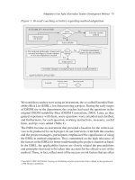
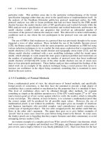
The four themes provide a framework for “bridging the gap” between a User’s abstract vision
and the physical realization of the system, product, or service. Thus, each theme builds on
decisions established by its predecessor and expands the level of detail of the evolving system
design solution as illustrated at the left side of in Figure 23.1. This allows us to make several
observations:
23.2 Introducing the Four Domains of Solution Development 243
Table 23.1 Linking Part I System Analysis Concepts themes into Part II System Design and Development
Practices semantics
ID Part I Thematic Objectives Domain Solutions
23.1 Objective 1—WHAT are the boundary conditions and constraints imposed Requirements
by the User on a system, product, or service in terms of missions within a Domain Solution
prescribed OPERATING ENVIRONMENT?
23.2 Objective 2—Given the set of boundary conditions and constraints, HOW Operations Domain
does the User envision deploying, operating, and supporting the system, Solution
product, or service to perform its missions within specific time limitations,
if applicable?
23.3 Objective 3—Given the deployment, operation, support, and time constraints Behavioral Domain
planned for the system, product, or service, WHAT is the set of outcome- Solution
based behaviors and responses required of the system to accomplish its
missions?
23.4 Objective 4—Given the set of outcome-based behaviors and responses Physical Domain
required of the system to accomplish its mission, HOW is the deliverable Solution
system, product, or service to be physically implemented to perform those
missions and demonstrate?
Simpo PDF Merge and Split Unregistered Version -
• The mission (i.e., the opportunity/problem space) forms the basis for the User to establish
the Requirements Domain Solution (i.e., the solution space).
• The Requirements Domain Solution forms the basis for developing and maturing the Oper-
ations Domain Solution.
• The evolving Operations Domain Solution forms the basis for developing and maturing the
Behavioral Domain Solution.
• The evolving Behavioral Domain Solution forms the basis for developing and maturing the
Physical Domain Solution based on physical components and technologies available.
From a workflow perspective, the design and development of the system solution evolves and
matures from the abstract to the physical over time. However, the workflow progression consists
of numerous feedback loops to preceding solutions as System Analysts and SEs mature the solu-
tions and reconcile critical operational and technical issues (COIs/CTIs). As a result, we symbol-
ize the system solution domains as shown at the right side of Figure 23.1.
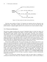
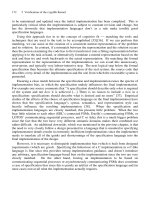
23.3 SYSTEM DOMAIN SOLUTION SEQUENCING
Figure 23.2 provides a way to better understand how the system domain solutions evolve over time.
As shown, the Requirements Domain Solution is initiated first, either in the form of a contract
System Performance Specification (SPS) or a System Developer’s item development specification.
Here is how the sequencing occurs:
• When the Requirements Domain Solution is understood and reaches a level of maturity suf-
ficient to develop concepts of operation, initiate the Operations Domain Solution.
• When the Operations Domain Solution reaches a level of maturity sufficient to define
relationships and interactions among system capabilities, initiate the Behavioral Domain
Solution.
244 Chapter 23 System Analysis Synthesis
The
Mission
Operations
Domain Solution
Requirements
Domain
Solution
Behavioral
Domain Solution
Physical Domain
Solution
Level of Detail Elaborated Expansion
1
2
3
4
A
bstract
P
hysical
Physical
Domain
Solution
Behavioral
Domain
Solution
Reqmts.
Domain
Solution
Operations
Domain
Solution
1
2
3
4
ExitEntry
Figure 23.1 Development and Evolution of a SYSTEM’s/Entity’s Solution Domains
Simpo PDF Merge and Split Unregistered Version -
• When the Behavioral Domain Solution reaches a level of maturity sufficient to allocate the
behavioral capabilities to physical components, initiate the Physical Domain Solution.
• Once initiated, the Requirements, Operations, Behavioral, and Physical Domain Solutions
evolve concurrently, mature, and stabilize.
23.4 SUMMARY
In this chapter we synthesized our discussions in Part I on system analysis concepts and established the foun-
dation for Part II on system design and development. The introduction of the Requirements, Operations,
Behavioral, and Physical Solution Domains, coupled with chapter references in each domain, encapsulate the
key system analysis concepts that enable us to THINK about, communicate, analyze, and organize systems,
products, and services for design and development. With this foundation in place, we are now ready to proceed
to Part II System Design and Development Practices.
23.4 Summary
245
Entry/Exit
Physical Domain Solu
tion
Physical Domain Solution4
Physical
Domain
Soluti
on
Behavioral
Domain
Soluti
on
Reqmts.
Domain
Soluti
on
Operations
Domain
Soluti
on
1
23
4
Level of
Detail
For each entity at every level of abstraction
Requirements Domain Solution
Requirements Domain Solution1
Operations Domain
Solution
Operations Domain Solution2
3
Behavioral Domain Solution
Time
Figure 23.2 System Solution Domain Time-Based Implementation
Simpo PDF Merge and Split Unregistered Version -
Simpo PDF Merge and Split Unregistered Version -
Part II
Systems Design and
Development Practices
EXECUTIVE SUMMARY
Part II, System Design and Development Practices, builds on the foundation established in Part I
System Analysis Concepts and consists of 34 chapters organized into six series of practices. The
six series consist of:
• System Development Strategies Practices
• System Specification Practices
• System Design and Development Practices
• Decision Support Practices
• System Verification and Validation Practices
• System Deployment, Operations, and Support Practices
As an introductory overview, let’s explore a brief synopsis of each of these practices.
System Development Strategy Practices
Successful system development requires establishing an insightful strategy and supporting work-
flow that employs proven practices to enable a program to efficiently progress from contract award
to system delivery and acceptance. The System Development Strategy Practices, which consists of
Chapter 24–27, provide insights for establishing a program strategy.
Our discussions describe how a program employs verification and validation concepts intro-
duced in Part I to create a workflow that translates multi-level specifications into a physical design
solution that leads to delivery of systems, products, or services. We explore various development
methods such as the waterfall approach, incremental development, evolutionary development, and
spiral development. We also dispel a myth that V & V are only performed after a system has been
integrated and tested; V & V are performed continuously from contract award through system deliv-
ery and acceptance.
Given an understanding of System Development Strategy Practices, we introduce the corner-
stone for system design and development via the System Specification Practices.
System Specification Practices
System design and development begins with the derivation and development of system specifica-
tions and requirements that bound the User’s solution space subject to technology, cost, schedule,
System Analysis, Design, and Development, by Charles S. Wasson
Copyright © 2006 by John Wiley & Sons, Inc.
Simpo PDF Merge and Split Unregistered Version -
248 Part II Systems Design and Development Practices
support, and risk constraints. The System Specification Series, which consist of Chapters 28–33,
explore what a specification is; types of specifications; how specifications are analyzed and devel-
oped; and how specification requirements are analyzed, derived, developed, and reviewed.
The System Specification Practices provide the cornerstone for our next topical discussion,
System Design and Development Practices.
System Design and Development Practices
The design and development of a system requires that the developers establish an in-depth under-
standing of WHAT the user is attempting to accomplish and select a solution from a set of viable
candidates based on decision factors such as technical, technology, support, cost, schedule, and risk.
The System Design and Development Practices series consists of Chapters 34–46 and cover a
diverse range of system design and development practices. Our discussions include: understanding
the operational utility, suitability, effectiveness, and availability requirements; formulation of
domain solutions; selection of a system architecture; configuration identification; system interface
design; standards and conventions; and design and development documentation.
The System Design and Development Practices require timely data to support informed deci-
sion making that the RIGHT system solution is selected. This brings us to our next topic, Decision
Support Practices, which provide the data.
Decision Support Practices
The design and development of integrated sets of system elements requires analytical support to
provide data and ensure that the system design balances technical, technology, support, cost, sched-
ule, and risk considerations. The Decision Support Practices series, which consist of Chapters
47–52, provide mechanisms that range from analyzes to prototypes and demonstrations to provide
timely data and recommendations.
Our discussions address analyses; statistical variation influences on system design; system per-
formance budgets and margins; system reliability, availability, and maintainability; system model-
ing and simulation; and trade study analysis of alternatives.
System design and development requires on-going integrity assessments to ensure that the
system is being designed correctly and will satisfy the user’s operational need(s). This brings us to
our next topic, Verification and Validation Practices, which enable us to assess the integrity of the
evolving system design solution.
Verification and Validation Practices
System design and development requires answering two key questions: 1) Is the system being
designed and developed RIGHT—in accordance with the contract requirements and 2) Does the
system satisfy the user’s operational needs? The Verification and Validation Practices series, which
consist of Chapters 53 through 55, enable the system users, acquirer, and developers to answer
these questions from contract award through system delivery and acceptance.
Our discussions explore what verification and validation are; describe the importance of tech-
nical reviews to verify and validate the evolving and maturing system design solution; and address
how system integration, test, and evaluation plays a key role in performing V & V. We introduce
verification methods such as inspection/examination, analysis, test, and demonstration that are
available for verifying compliance to specification requirements.
Once a system is verified, validated, and delivered for final acceptance, the user is ready to
employ the system to perform organizational missions. This brings us to our next topic, System
Deployment, Operations, and Support Practices.
Simpo PDF Merge and Split Unregistered Version -
System Deployment, Operations, and Support Practices
People often believe that SE and analysis end with system delivery and acceptance by the user; SE
continues throughout the operational life of the system, product, or service. The System Deploy-
ment, Operations, and Support Practices series, which consist of Chapters 56 and 57, provide key
insights into system and mission applications and performance that require system analyst and SE
assessments, not only for corrective actions to the current system but requirements for future
systems and capabilities.
Our discussions explore how a system is deployed including site selection, development, and
activation; describe key considerations required for system integration at a site into a higher level
system; address how system deficiencies are investigated and form the basis for acquisition require-
ments for new systems, products, or services; and investigate key engineering considerations that
must be translated into specification requirements for new systems.
Part II Systems Design and Development Practices 249
Simpo PDF Merge and Split Unregistered Version -
Simpo PDF Merge and Split Unregistered Version -
Chapter 24
System Development
Workflow Strategy
24.1 INTRODUCTION
The award of a system development contract to a System Developer or Services Provider signifies
the beginning of the System Development Phase. This phase covers all activities required to
meet the provisions of the contract, produce the end item deliverable(s), and deploy or distribute
the deliverables to the designated contract delivery site.
On contract award, the Offeror transforms itself from a proposal organization to a System
Developer or Service Provider organization. This requires the organization to demonstrate that they
can competently deliver the proposed system on time and within budget in accordance with the
provisions of the contract. This transformation is best captured in a business jest: “The good news
is we won the contract! The bad news is WHAT have we done to ourselves?”
Our discussion of this phase focuses on how a proposed system is developed and delivered to
the User. We explore how the System Developer or Service Provider evolves the visionary and
abstract set of User requirements through the various stages of system development to ultimately
produce a physical system. The “system” may be country, a space shuttle, a mass mailing service,
a trucking company, a hospital, or a symposium. The important point to keep in mind is that the
duration of the System Development Phase may last from a few weeks or months to several years.
Author’s Note 24.1 The System Development Phase described here, in conjunction with the
System Procurement Phase, may be repeated several times before a final system is fielded. For
example, in some domains, the selection of a System Developer may require several sequences of
System Development Phase contracts to evolve the system requirements and down select from a
field of qualified contractors to one or two contractors. Such is the case with spiral development.
For a System Service Provider contract, the System Development Phase may be a preparatory
time to develop or adapt reusable system operations, processes, and procedures to support the con-
tract’s mission, support services for the System Operations Phase. For example, a healthcare insur-
ance provider may win a contract to deliver “outsourced” support services for a corporation’s
insurance program. The delivered services may be a “tailored” version similar to programs the
contractor has administered for other organizations.
Once you have mastered the concepts discussed in this section, you should have a firm under-
standing of how the SE process should be implemented and how to manage its implementation.
System Analysis, Design, and Development, by Charles S. Wasson
Copyright © 2006 by John Wiley & Sons, Inc.
251
Simpo PDF Merge and Split Unregistered Version -
252 Chapter 24 System Development Workflow Strategy
What You Should Learn from This Chapter
1. What are the workflow steps in system development?
2. What is the verification and validation (V&V) strategy for system development?
3. How does the V&V strategy relate to the system development workflow?
4. Why is the V and V strategy important?
5. What is the Developmental Configuration?
6. When does the Developmental Configuration start and end?
7. What is a first article system?
8. What is developmental test and evaluation (DT&E)?
9. How is DT&E performed?
10. When is DT&E performed during the System Development Phase?
11. Who is responsible for performing DT & E?
12. What is operational test & evaluation (OT&E)?
13. When is OT&E performed during the System Development Phase?
14. What is the objective of OT&E?
15. Who is responsible for performing OT&E?
16. What is the System Developer’s role in OT&E?
Definitions of Key Terms
• Developmental Test and Evaluation (DT&E) “Test and evaluation performed to:
1. Identify potential operational and technological limitations of the alternative concepts and
design options being pursued.
2. Support the identification of cost-performance trade-offs.
3. Support the identification and description of design risks.
4. Substantiate that contract technical performance and manufacturing process requirements
have been achieved.
5. Support the decision to certify the system ready for operational test and evaluation.”
(Source: MIL-HDBK-1908, Section 3.0, Definitions, p. 12)
• Developmental Configuration “The contractor’s design and associated technical docu-
mentation that defines the evolving configuration of a configuration item during develop-
ment. It is under the developing contractor’s configuration control and describes the design
definition and implementation. The developmental configuration for a configuration item
consists of the contractor’s released hardware and software designs and associated technical
documentation until establishment of the formal product baseline.” (Source: MIL-STD-973
(Canceled), Configuration Management, para. 3.30)
• First Article “[I]ncludes preproduction models, initial production samples, test samples,
first lots, pilot models, and pilot lots; and approval involves testing and evaluating the first
article for conformance with specified contract requirements before or in the initial stage of
production under a contract.” (Source: DSMC—Test & Evaluation Management Guide,
Appendix B, Glossary of Test Terminology)
• Functional Configuration Audit (FCA) “An audit conducted to verify that the development
of a configuration item has been completed satisfactorily, that the item has achieved the per-
formance and functional characteristics specified in the functional or allocated configuration
Simpo PDF Merge and Split Unregistered Version -
24.2 System Development Verification and Validation Strategy 253
identification, and that its operational and support documents are complete and satisfactory.”
(Source: IEEE 610.12-1990 Standard Glossary of Software Engineering Terminology)
• Independent Test Agency (ITA) An independent organization employed by the Acquirer
to represent the User’s interests and evaluate how well the verified system satisfies the User’s
validated operational needs under field operating conditions in areas such as operational
utility, suitability, and effectiveness.
• Operational Test and Evaluation (OT&E) Field test and evaluation activities performed
by the User or an Independent Test Agency (ITA) under actual OPERATING ENVIRON-
MENT conditions to assess the operational utility, suitability, and effectiveness of a system
based on validated User operational needs. The activities may include considerations such
as training effectiveness, logistics supportability, reliability and maintainability demonstra-
tions, and efficiency.
• Physical Configuration Audit (PCA) “An audit conducted to verify that a configuration
item, as built, conforms to the technical documentation that defines it.” (Source: IEEE
610.12-1990 Standard Glossary of Software Engineering Terminology)
• Quality Record (QR) A document such as a memo, e-mail, report, analysis, meeting
minutes, and action items that serves as objective evidence to commemorate a task-based
action or event performed.
Phase Objective(s)
The primary objective of the System Development Phase is to translate the contract and System
Performance Specification (SPS) requirements into a physical, deliverable system that has been:
1. Verified against those requirements.
2. Validated by the User, if required.
3. Formally accepted by the User or the Acquirer, as the User’s contract and technical
representative.
24.2 SYSTEM DEVELOPMENT VERIFICATION
AND VALIDATION STRATEGY
During our discussion of system entity concepts in Figure 6.2 we explored the basic concept of
system verification and validation. Verification and validation (V&V) provides the basis for a con-
ceptual strategy to ensure the integrity of an evolving SE design solution. Let’s expand on Figure
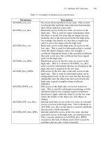
6.2 to establish the technical and programmatic foundation for our discussion in this chapter. Figure
24.1 serves as a navigation aid for our discussion for a closed loop V&V system.
System Definition and System Procurement Phases V&V
When the User identifies an Operational Need (1), the User may employ the services of an Acquirer
to serve as a contract and technical representative for the procurement action. The operational
needs, which may already be documented in a Mission Needs Statement (MNS), are translated by
the Acquirer into an Operational Requirements Document (ORD) (2) and validated in collabora-
tion with the User. The ORD becomes the basis for the Acquirer to develop a System Requirements
Document (SRD) (3) or Statement of Objectives (SOO). The SRD/SOO specifies the technical
requirements for the formal solicitation—namely the Request for Proposal (RFP)—in an OPEN
competition to qualified Offerors.
Simpo PDF Merge and Split Unregistered Version -
Offerors analyze the SRD/SOO, derive and develop a System Performance Specification (SPS)
(4) from the SRD/SOO (2), and submit the SPS as part of their proposal. When the Acquirer makes
a final source selection decision, a System Development Agreement (6) is formally established at
the time of contract award (5).
System Development Phase V&V
The SPS (4) provides the technical basis for developing the deliverable system or product via
System Engineering and Development (6) activities. Depending on the maturity of the require-
ments, the System Developer may employ spiral development and other strategies to develop the
system design solution. In support of the system engineering and development (6) activity, Deci-
sion Support (8) performs analyses and trade studies, among other such activities, with inputs and
preliminary assessments provided from User Feedback (9), such as validation on the implementa-
tion of requirements.
As the SE design evolves, System Verification (12) methods are continually applied to assess
the requirements allocation, flow down, and designs at all levels of abstraction—at the PRODUCT,
SUBSYSTEM, ASSEMBLY, SUBASSEMBLY, and PART levels. Design verification activities
include Developmental Test and Evaluation (DT&E) (10) and Major Technical Reviews and Trace-
ability Audits (11). The purpose of these verification activities is to assess and monitor the progress,
maturity, integrity and risk of the SE design solution. Baselines are established at critical staging
or control points—using technical reviews—to capture formal baselines of the evolving Develop-
mental Configuration to facilitate decision making.
Author’s Note 24.2 Although it isn’t explicitly shown in Figure 24.1, validation activities con-
tinually occur within the System Developer’s program organization. Owners VALIDATE lower level
design solution implementations in terms of documented use case-based requirements.
254
Chapter 24 System Development Workflow Strategy
Operational
Need
System
Engineering &
Development
System Verification
Did We Build the Product Right?
System Verification
Did We Build the Product Right?
Operational Test &
Evaluation (OT&E)
System
Verification
Test (SVT)
Decision Support
Analyses, Trade
Studies, Models,
Simulations, &
Prototypes
7
8
FCA
15
12
19
PCA
SVR
16 18
TRRs
14
Operational
Requirements
Document
(ORD)
2
System
Requirements
Document
(SRD)
3
System
Performance
Specification
(SPS)
4
System Development Phase
6
Customer Satisfaction22
20
System Validation
Did We Acquire the Right Product?
21
17
5
13
Contract
Award
Major Technical Reviews
& Traceability Audits
11
CDR
User
Feedback
9
Developmental Test & Evaluation (DT&E) 10
1
Figure 24.1 System V & V—Programmatic Perspective
Simpo PDF Merge and Split Unregistered Version -
24.3 Implementing the System Development Phase 255
Design requirements established at the Critical Design Review (CDR) (13) provide the basis for
procuring and developing components. As each component is completed, the item is verified for
compliance to its current design requirements baseline.
Successive levels of components progress through levels of System Integration, Test, and Eval-
uation (SITE) and verified against their respective item development specifications (IDSs). Test
Readiness Reviews (TRRs) (14) are conducted at various levels of integration to verify that all
aspects of a configuration and test environment are ready to commence testing with low risk.
When the SYSTEM level of integration is ready to be verified against the SPS (4), a System
Verification Test (SVT) (15) is conducted. The SVT must answer the question “Did we build the
system or product RIGHT?”—in accordance with the SPS (4) requirements.
Following the SVT, a Functional Configuration Audit (FCA) (16) is conducted to authenticate
the SVT results, via quality records (QRs), as compliant with the SPS (4) requirements. The FCA
may be followed by a Physical Configuration Audit (PCA) (17) to authenticate by physical meas-
urement compliance of items against their respective design requirements. On completion of the
FCA (16) and PCA (17), a System Verification Review (SVR) (18) is conducted to certify the results
of the FCA and PCA.
Depending on the terms and conditions (T&Cs) of the System Development Agreement (6),
completion of the SVR (18) serves as prerequisite for final system or product delivery and accept-
ance (19) by the Acquirer for the User. For some agreements an Operational Test and Evaluation
(OT&E) (20) may be required. In preparation for the OT&E (20), the User or an Independent Test
Agency (ITA) representing the User’s interests may be employed to conduct scenario-based field
exercises using the system or product under actual or similar OPERATING ENVIRONMENT
conditions.
During OT&E (20), Acquirer System Validation (21) activities are conducted to answer the
question “Did we acquire the RIGHT system or product?”—as documented in the ORD or the SOO,
whichever is applicable. Depending on the scope of the contract (5), corrective actions may be
required during OT&E (20) for any design flaws, latent defects, deficiencies, and the like. Follow-
ing OT&E (20), the ITA prepares an assessment and recommendations.
Author’s Note 24.3 Although the System Development contract (6) may be complete, the User
performs system verification and validation activities continuously throughout the System Devel-
opment and system Operations and Support (O&S) phases of the system product life cycle. V&V
activities expand to encompass organizational and system missions. As competitive and adversar-
ial threats in the OPERATING ENVIRONMENT evolve and maintenance costs increase, “gaps”
emerge in achieving organizational and system missions with existing capabilities. These degree
of urgency to close these gaps subsequently leads to the next system or product development or
upgrade to existing capabilities.
Now that we have established the V&V strategy of system development, the question is: HOW do
we implement it? This brings us to our next topic, Implementing the system development phase.
24.3 IMPLEMENTING THE SYSTEM DEVELOPMENT PHASE
The workflow during the system development phase consists of five sequential workflow processes
as illustrated in Figure 24.2. The processes consist of:
1. System Design Process
2. Component Procurement and Development Process
Simpo PDF Merge and Split Unregistered Version -
3. System Integration, Test, and Evaluation (SITE) Process
4. Authenticate System Baseline Process
5. Operational Test, and Evaluation (OT&E) Process
While the general workflow appears to be sequential, there are highly iterative feedback loops that
connect to predecessor segements.
The System Development Phase begins at contract award and continues through deliverable
system acceptance by the Acquirer and User. During this phase the approach that enabled the
System Developer or Service Provider to convince the Acquirer that the organization can perform
on the contract is implemented. Remember those brochureware phrases: well-organized, seamless
organization, highly efficient, highly trained and performing teams; no problem, and so on.
The System Development Phase includes those technical activities required to translate the
contract performance specifications into a physical system solution. We refer to the initial system(s)
as the first article of the Developmental Configuration. Throughout the phase, the highly iterative
system design solution evolves through a progression of maturity stages. Each stage of maturity
typically consists of a series of design reviews with entry and exit criteria supported by analyses,
prototypes, and technology demonstrations. The reviews culminate in design baselines that capture
snapshots of the evolving Developmental Configuration. When the system design solution is for-
mally approved at a Critical Design Review (CDR), the Developmental Configuration provides the
basis for component procurement and/or development.
Procured and developed components are inspected, integrated, and verified against their respec-
tive design requirements-drawings- and performance specifications at various levels of integration.
The intent of verification is to answer the question: “Did we develop the system RIGHT?”—accord-
ing to the specification requirements. The integration culminates with a System Verification Test
(SVT) against the System Performance Specification (SPS). Since the System Development Phase
focuses on development of the system, product, or service, testing throughout SVT is referred to
as Developmental Test and Evaluation (DT&E).
256
Chapter 24 System Development Workflow Strategy
System
Production
Phase
System
Operations &
Support Phase
System
Disposal
Phase
System
Definition
Phase
System
Procurement
Phase
Technical Management Process
7
Component
Procurement
&
Development
Process
System
Integration, Test,
& Evaluation
(SITE) Process
Authenticate
System
Baselines
Process
Process
Operational
Test &
Evaluation
(OT&E)
Process
3 4 5 6
Decision Support Process
8
Systems
Design
Process
2
Highly
Iterative
Highly
Iterative
Highly
Iterative
Highly
Iterative
System Development Phase
1
System/Product Life Cycle
Figure 24.2 The System Development Process Work flow
Simpo PDF Merge and Split Unregistered Version -
When the first article system(s) of the Developmental Configuration has been verified as
meeting its SPS requirements, one of two options may occur, depending on contract requirements.
The system may be deployed to either of the following:
1. Another location for validation testing by the User or an Independent Test Agency (ITA)
representing the User’s interests.
2. The User’s designated field site for installation, checkout, integration into the user’s Level
0 system, and final acceptance.
Validation testing, which is referred to as Operational Test and Evaluation (OT&E), enables the
User to make a determination if they specified and procured the RIGHT SYSTEM to meet their
validated operational needs. Any deficiencies are documented as discrepancy reports (DRs) and
resolved in accordance with the terms and conditions (Ts&Cs) of the contract.
After an initial period of system operational use in the field to correct latent defects such as
design flaws, errors and deficiencies and collect field data to validate system operations, a decision
is made to begin the System Production Phase, if applicable. If the User does not intend to place
the system or product in production, the Acquirer formally accepts system delivery, thereby initi-
ating the System Operations and Support (O&S) Phase.
Technical Management Process
The technical orchestration of the System Development Phase resides with the Technical Manage-
ment Process. The objective of this process is to plan, staff, direct, and control product-based team
activities focused on delivering their assigned items within technical, technology, cost, schedule,
and risk constraints.
Decision Support Process
The Decision Support Process supports all aspects of the System Development Phase process
decision-making activities. This includes conducting analyses, trade studies, modeling, simulation,
testing, and technology demonstrations to collect data to validate models and provide prioritized
recommendations to support informed decision making within each of the workflow processes.
Exit to System Production Phase or
System Deployment Phase
When the System Development Phase is completed, the workflow progresses to the System Pro-
duction Phase or System Operations and Support (O&S) Phase, whichever is applicable.
Guidepost 24.1 Based on a description of the System Development Phase workflow processes,
let’s investigate HOW the V&V strategy is integrated with the workflow progression.
24.4 APPLYING V&V TO THE SYSTEM
DEVELOPMENT WORKFLOW
So far we have introduced the System Development Phase processes and described the sequential
workflow. Each of these processes enables the System Developer to accomplish specific objectives
such as:
1. Select and mature a design from a set of viable candidate solutions based on an analysis of
alternatives.
24.4 Applying V&V to the System Development Workflow 257
Simpo PDF Merge and Split Unregistered Version -
258 Chapter 24 System Development Workflow Strategy
2. Procure, fabricate, code, and test PART level components.
3. Perform multi-level system integration, test, and evaluation.
4. Verify items at each level of integration satisfy specification requirements.
5. Validate, if applicable, the integrated SYSTEM as meeting User operational needs.
Until the system is delivered and accepted by the Acquirer, the Developmental Configuration, which
captures the various design baselines, is always in a state of evolution. It may require redesign or
rework to correct latent defects, deficiencies, errors, and the like. So how do we minimize the
impacts of these effects? This brings us to the need for an integrated verification and validation
(V&V) strategy. To facilitate our discussion, Figure 24.3 provides a framework.
System Performance Specification (SPS) V&V Strategy
During the System Procurement Phase, Operational Needs (1) identified by the User and Acquirer
are documented (2) in the System Performance Specification (SPS) (3). This is a critical step. The
reason is that by this point the Acquirer, in collaboration with the User, has partitioned the organi-
zational problem space into one or more solution spaces.
Each solution space is bounded by requirements specified in its SPS. If there are any errors in
tactical or engineering judgment, they manifest themselves in the requirements documented in the
SPS. Therefore the challenge question for the Acquirer, User, and ultimately the System Developer
is: Have we specified the RIGHT system—solution space—to satisfy one or more operational
needs—problem space? How do we answer this question?
SPS requirements should be subjected to Requirements Validation (4) against the Operational
Need (1) to validate that the right solution space description has been accurately and precisely
bounded by the SPS (3).
System
Verification
Procedures
14
System
Performance
Specification
3
System
Engineering
Design
Process
7
18
Developmental Test & Evaluation (DT&E) 12
System
Engineering
Design
Process
Component
Procurement &
Development
Process
System
Integration,
Test, &
Evaluation
Process
OT&E
Process
OT&E
Process
Verified &
Validated
System
22
Design Verification
Component
Verification
System Verification
6 10
16
2
Design
Validation
Requirements
Validation
4
System Validation
5
Operational
Need(s)
1
20
8
11
Verification Procedures
15
Design
Requirements
9
13
(18) Not Shown
·
Authenticate System Baselines
Process
·
System Delivery Process
·
Install & C.O. System Process
Verification Methods &
Requirements
17
·
Functional Configuration Audit (FCA)
·
Physical Configuration Audit(PCA)
19
Figure 24.3 Development Process Context System Verification and Validation Concept
Simpo PDF Merge and Split Unregistered Version -
Author’s Note 24.4 A word of caution: any discussions with the User and Procurement Team
regarding the System Performance Specification (SPS) requirements validation requires tactful pro-
fessionalism and sensitivity. In effect, you are validating that the Acquirer performed their job cor-
rectly. On the one hand they may be grateful for you identified any potential deficiencies in their
assessment. Conversely, you may highly offend! Approach any discussions in a tactful, well-
conceived, professional manner.
SE Design V&V Strategy
When the SPS requirements have been validated, the SPS (3) serves as originating or source
requirements inputs to system design. During the system design, Interim Design Verification (6) is
performed on the evolving system design solution by tracing allocated requirements back to the
SPS and prototyping design areas for RISK mitigation and critical operational or technical issue
(COI/CTI) resolution. Design Validation (7) activities should also be performed to confirm that the
User and Acquirer, as the User’s technical representative, agree that the evolving System Design
Solution satisfies their needs.
Author’s Note 24.5 The Interim Design Verification (6) and Interim Design Validation (7), or
design “verification and validation,” are considered complete when the system has been verified,
validated, and legally accepted by the User via the Acquirer in accordance with the terms of the
contract. Therefore the term “interim” is applied.
Design verification and validation occurs throughout the SE Design Process. Validation is accom-
plished via: 1) technical reviews (e.g., SDR, SSR, PDR, and CDR) and 2) technical demonstra-
tions. Communications media such as conceptual views, sketches, drawings, presentations,
technical demonstrations, and/or prototypes are used to obtain Acquirer and User validation accept-
ance and approval, as appropriate. On completion of a system level CDR, workflow progresses to
Component Procurement and Development (8).
Component Procurement and Development V&V Strategy
During Component Procurement and Development (8), design requirements from the System
Design (5) serve as the basis for procuring, fabricating, coding, and assembling system compo-
nents. Each component undergoes component verification (10) against its Design Requirements (5).
As components are verified, workflow progresses to System Integration, Test, and Evaluation
(SITE) (11).
System Integration, Test, and Evaluation (SITE) V&V Strategy
When components complete verification, they enter System Integration, Test, and Evaluation (11).
Activities performed during this process are often referred to as developmental test and evaluation
(DT&E) (12). DT&E occurs throughout the entire System Development Phase, from System Design
(5) through SITE (11). The purpose of DT&E in this context is to verify that the system and its
embedded subsystems, HWCIs/CSCIs, assemblies, and parts are compatible and interoperable with
themselves and the system’s external interfaces.
To accomplish the SITE Process, Verification Methods and Requirements (13) defined in the
SPS (3) and multi-level item development specifications (IDSs) are used to develop Verification
Procedures (14). Verification methods—consisting of inspection, analysis, test, demonstration, and
similarity—are defined by the SPS for each requirement and used as the basis for verifying com-
pliance. One or more detailed test procedures (14) that prescribe the test environment configura-
24.4 Applying V&V to the System Development Workflow 259
Simpo PDF Merge and Split Unregistered Version -
tion—such as the OPERATING ENVIRONMENT (initial and dynamic), data inputs, and expected
test results—support each verification method.
During SITE (11), the System Developer formally tests the SYSTEM with representatives of
the Acquirer and User as witnesses. Multi-level system verification activities, at appropriate inte-
gration points (IPs) review (15) test data and results against the verification procedures (14) and
expected results specified in the appropriate development specifications. When the system com-
pletes SITE (11), a formal System Verification Test (SVT) corroborates the system’s capabilities
and performance against the SPS.
Authenticate System Baselines V&V Strategy—First Pass
When the SVT is completed, workflow progresses to Authenticate System Baselines (18). The
process contains two authentication processes that may be performed at different times, depending
on contract requirements. The first authentication consists of a Functional Configuration Audit
(FCA) (17). Using the SPS and other development specification requirements as a basis, the FCA
reviews the results of the As-Designed, Built, and Verified system that has just completed the SVT
to verify that it fully complies with the SPS functional and performance requirements. The FCA
may be conducted at various levels of IPs during the SITE Process.
On successful completion of the FCA, the system may be deployed to a User’s test range or
site to undergo Operational Test and Evaluation (OT&E) (19). On completion of OT&E, the system
may reenter the Authenticate System Baselines process for the second pass.
Validate System Process V&V Strategy
Up to this point, the system is verified by SVT and audited by FCA to meet the SPS requirements.
The next step is to validate that the As-Designed, Built, and Verified system satisfies the User’s
Operational Needs (1) as part of the Operational Test and Evaluation (OT&E) (20) activities.
System validation activities (20) demonstrate how well the fielded system performs missions
in its intended operational environment as originally envisioned by the User. Any system latent
defects and deficiencies discovered during system validation are recorded as problem reports and
submitted to the appropriate decision authority for disposition and corrective action, if required.
Author’s Note 24.6 During system validation, a determination is made that an identified defi-
ciency is within the scope of the original contract’s SPS. This is a critical issue. For example, did
the User or Acquirer overlook a specific capability as an operational need and failed to document
it in the SPS? This point reinforces the need to perform a credible Requirements Validation (4)
activity prior to or immediately after Contract Award to AVOID surprises during system accept-
ance. If the deficiency is not within the scope of the contract, the Acquirer may be confronted with
modifying the contract and funding additional design implementation and efforts to incorporate
changes to correct the deficiency.
Authenticate System Baselines V&V Strategy—Second Pass
During the second pass through Authenticate System Baselines (18), the As Designed, Built, Ver-
ified, and Validated (20) configuration system is subjected to a Physical Configuration Audit (PCA)
(17). PCA audits the As-Designed, Built, and Verified physical system to determine if it fully com-
plies with its design requirements such as drawings and parts lists. On successful completion of
the PCA (17), a System Verification Review (SVR) is conducted to:
1. Certify the results of the FCA and PCA.
2. Resolve any outstanding FCA/PCA issues related to those results.
3. Assess readiness-to-ship decision.
260
Chapter 24 System Development Workflow Strategy
Simpo PDF Merge and Split Unregistered Version -
On successful completion of the OT&E Process (19), a Verified and Validated System (22) should
be ready for delivery to the User via formal acceptance by the Acquirer.
Guidepost 24.2 Integrating the V&V strategy into the System Development Phase workflow
describes the mechanics of ensuring the evolving Development Configuration is progressing to a
plan. However, performing to a plan does not guarantee that the system can be completed suc-
cessfully on schedule and within budget. The development, especially for large, complex systems,
must resolve critical operational and technical issues (COIs/CTIs), each with one or more risks.
So how do we mitigate these risks? This brings us to our next topical discussion, the roles of the
Developmental Test and Evaluation (DT&E) and the Operational Test and Evaluation (OT&E).
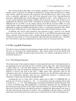
24.5 RISK MITIGATION WITH DT&E AND OT&E
Satisfactory completion of system development requires that a robust strategy be established up
front. We noted earlier that although the workflow appears to be sequential, each process consists
of highly iterative feedback loops with each other as illustrated by Figure 24.4. To accomplish this,
two types of testing occur during the System Development Phase: 1) Developmental Test & Eval-
uation (DT & E) and 2) Operational Test & Evaluation (OT & E).
Developmental Test and Evaluation (DT&E)
Developmental testing (DT) serves as a risk mitigation approach to ensure that the evolving system
design solution, including its components, complies with the System Performance Specification
(SPS) requirements. DT focuses on two themes:
1. Are we building the system or product right—meaning using best practices in compliance
with the SPS.
2. Do we have a design solution that represents the best, acceptable risk solution for a given
set of technical, cost, technology, and schedule constraints?
24.5 Risk Mitigation with DT&E and OT&E 261
OT&E
Assessment
Report
Multi-Level SE
“Design To”
Specifications
Multi-Level SE
“Build To”
Requirements
Multi-Level
Component
Procurement/
Development
Multi-Level
System
Integration,
Test, &
Evaluation
System
Performance
Specification
(SPS)
Operational
Requirements
Document
(ORD)
System
Requirements
Document
(SRD)
Requirements
Verification &
Validation
Design
Verification &
Validation
Component Level
Verification
Multi-Level System Integration Verification & Validation
System Level Verification
Test &
Evaluation
Master
Plan
(TEMP)
Developmental Test & Evaluation (DT&E)
Are We Developing the System RIGHT in accordance with the Specification Requirements?
Conduct
Operational
Scenario-Based
Fi
eld Tests
Operational Test & Evaluation (OT&E)
Did We Acquire the RIGHT System to Meet the End User’s
Intended Operational Ne
eds?
Mission
Needs
Statement
(MNS)
OR
2
4
5
6 7 8 9
10
12 13 14
11
Verified
Test
Article(s
)
1
3
Requirements
Verification
& Validation
Statement
of
Objectives
(SOO)
Figure 24.4 System V & V—Technical Perspective
Simpo PDF Merge and Split Unregistered Version -
262 Chapter 24 System Development Workflow Strategy
The DSMC T&E Management Guide states that the objectives of DT&E are to:
1. Identify potential operational and technological capabilities and limitations of the alterna-
tive concepts and design options being pursued;
2. Support the identification of cost-performance tradeoffs by providing analyses of the capa-
bilities and limitations of alternatives;
3. Support the identification and description of design technical risks;
4. Assess progress toward meeting critical operational issues (COIs), mitigation of
acquisition technical risk, achievement of manufacturing process requirements and system
maturity;
5. Assess validity of assumptions and conclusions from the analysis of alternatives (AOA);
6. Provide data and analysis in support of the decision to certify the system ready for opera-
tional test and evaluation (OT&E);
7. In the case of automated information systems, support an information systems security cer-
tification prior to processing classified or sensitive data and ensure a standards conformance
certification.
(Source: Adapted from DSMC Test & Evaluation Management Guide, App. B, p. B-6)
DT&E is performed throughout System Design Process, Component and Procurement Process,
and the SITE Process. Each process task verifies that the evolving and maturing system or product
design solution—the Developmental Configuration—fully complies with the SPS requirements.
This is accomplished via reviews, proof of principle and proof of concept demonstrations, tech-
nology demonstrations, engineering models, simulations, brass boards, and prototypes.
On completion of verification, the physical system or product enters OT&E, whereby it is val-
idated against the User’s documented operational need.
Operational Test and Evaluation (OT&E)
Operational test and evaluation (OT&E) activities are typically conducted on large, complex
systems such as aircraft and military acquirer activity systems. The theme of OT&E is: Did we
acquire the RIGHT system or product to satisfy our operational need(s)? OT&E consists of sub-
jecting the test articles to actual field environmental conditions with operators from the User’s
organization. An Independent Test Agency (ITA) designated by the Acquirer or User typically con-
ducts this testing. To ensure independence and avoid conflicts of interest, the contract precludes
the System Developer from direct participation in OT&E; the System Developer may, however,
provide maintenance support, if required.
Since the OT&E is dependent on how well the system’s Users perform with the new
system or product, the ITA or System Developer train the User’s personnel to safely operate the
system. This may occur prior to system deployment following the SVT or on arrival at the OT&E
site.
During the OT&E, the ITA trains the User’s personnel in how to conduct various operational
use cases and scenarios under actual field OPERATING ENVIRONMENT conditions. The use
cases and scenarios are structured to evaluate system operational utility, suitability, availability,
and effectiveness. ITA personnel instrument the SYSTEM to record and observe the human–system
interactions and responses. Results of the interactions are scored, summarized, and presented as
recommendations.
On successful completion of the DT&E and OT&E and the follow-on Authenticate System
Baselines Process, the verified and validated system or product is delivered to the Acquirer or User
for final acceptance.
Simpo PDF Merge and Split Unregistered Version -
24.6 GUIDING PRINCIPLES
In summary, the preceding discussions provide the basis with which to establish the guiding prin-
ciples that govern system development workflow strategy practices.
Principle 24.1 A system development strategy must have three elements:
1. A strategy-based roadmap to get from Contract Award to system delivery and acceptance
supported by incremental verification and validation.
2. A plan of action for implementing the strategy.
3. Documented objective evidence that you performed to the plan via work product quality
records.
Principle 24.2 System verification and validation applies to every stage of product development
workflow beginning at Contract Award and continuing until system delivery and acceptance.
Principle 24.3 Developmental test and evaluation (DT&E) is performed by the System Devel-
oper to mitigate Developmental Configuration risks; Users employ the operational test and evalu-
ation (OT&E) to determine if they acquired the right system.
24.7 SUMMARY
During our discussion of the system development workflow strategy we introduced the system development
phase processes. The System Development Phase processes include:
1. System Design
2. Component Procurement and Development
3. System Integration, Test, and Evaluation (SITE)
4. Authenticate System Baseline
5. Operational Test, and Evaluation (OT&E)
Based on the System Development Phase processes, we described an overall workflow strategy for ver-
ification and validation. This strategy provides the high-level framework for transforming a User’s validated
operational need into a deliverable system, product, or service.
We introduced the concepts of developmental test and evaluation (DT&E) and operational test and eval-
uation (OT&E). Our discussion covered how DT&E and OT&E serve as key verification and validation activ-
ities and their relationship to the system development workflow strategy.
GENERAL EXERCISES
1. Answer each of the What You Should Learn from This Chapter questions identified in the Introduction.
2. Using a system listed in Table 2.1, develop a description of the activities for each System Development
Phase process to be employed and integrated into an overall V & V strategy.
ORGANIZATIONAL CENTRIC EXERCISES
1. Research your organization’s command media for guidance and direction in implementing the System
Development Phase from an SE perspective.
(a) What requirements are levied on SE contributions?
Organizational Centric Exercises
263
Simpo PDF Merge and Split Unregistered Version -