System Analysis, Design, and Development Concepts, Principles, and Practices phần 7 pps
Bạn đang xem bản rút gọn của tài liệu. Xem và tải ngay bản đầy đủ của tài liệu tại đây (2.9 MB, 84 trang )
• Configuration Item (CI) “An aggregation of hardware, firmware, computer software, or
any of their discrete portions, which satisfies an end use function and is designated by the
(Acquirer) for separate configuration management. Configuration items may vary widely in
complexity, size, and type. Any item required for logistic support and designated for sepa-
rate procurement is a CI.” (Source: Adapted from DSMC Glossary: Defense Acquisition
Acronyms and Terms)
• Configuration Management “A management process for establishing and maintaining con-
sistency of a product’s performance, functional, and physical attributes with its requirements,
design and operational information throughout its life.” (Source: ANSI-EIA-649-1998, p. 4)
• Effectivity “A designation defining the product range (e.g., serial, lot numbers, model,
dates) or event at which a change to a specific product is to be (or has been) effected or to
which a variance applies.” (Source: ANSI-EIA-649-1998, p. 4)
• Hardware Configuration Item (HWCI) “An aggregation of hardware that satisfies an end
use function and is designated for separate configuration management by the Acquirer.”
(Source: Adapted from former MIL-STD-498, p. 5)
• Item Any physical component of a system such as a PRODUCT, SUBSYSTEM, ASSEM-
BLY, SUBASSEMBLY, or PART.
• Line Replaceable Unit (LRU) “A unit designed to be removed upon failure from a larger
entity (product or item) in the operational environment, normally at the organizational level.”
(Source: MIL-HDBK-470A, Appendix G, Glossary, p. G-8)
• Logical Configuration Item (LCI) An optional designation assigned to a specific
capability.
• Physical Configuration Item (PCI) An item that represents the physical instance of a con-
figuration item (CI). Each item is assigned a part number and may be serialized.
• Product Structure Refer to definition provided in Chapter 9 System Levels of Abstraction
and Semantics.
• Requirements Baseline “Documentation describing a system’s/segments functional char-
acteristics and the verification required to demonstrate the achievement of those specified
functional characteristics. The system or segment specification establishes the functional
baseline” (Source: DSMC Glossary: Defense Acquisition Acronyms and Terms)
• Variance, Deviation, Waiver, Departure “A specific written authorization to depart from
a particular requirement(s) of a product’s current approved configuration documentation for
a specific number of units or a specified time period. (A variance differs from an engineer-
ing change in that an approved engineering change requires corresponding revision of the
product’s current approved configuration documentation, whereas a variance does not.)”
(Source: ANSI/EIA-649-1998, Section 3.0, Definitions, p. 6)
Items—Building Blocks of Systems
Large, complex systems are developed by groups of people working as Integrated Product Teams
(IPTs) or development teams with assigned roles and responsibilities for producing various system
products. Depending on the size and complexity of the system or item being developed, teams are
assigned tasks such as specifying, designing, developing, integrating, and verifying various com-
ponents within the system. This presents some significant challenges:
1. How do you partition the architecture of the EQUIPMENT element into multiple levels and
instances of manageable physical items?
42.1 Introduction 491
Simpo PDF Merge and Split Unregistered Version -
2. How can people establish semantics that enable them to communicate with others about
the types of items they are developing or procuring from external vendors?
3. How can people communicate about the evolution of system components that go through
various stages from abstract system specification entities into physical components used to
build the system?
The solution resides in integrated building blocks referred to as items, configuration items (CIs),
hardware configuration items (HWCIs), and software configuration items (CSCIs). Each of these
building blocks represents semantics used to identify abstract entities within a system and their evo-
lution from SPS to deliverables.
42.2 UNDERSTANDING CONFIGURATION
IDENTIFICATION SEMANTICS
Configuration identification knowledge for most SEs typically comes from informal exposure via
verbal discussions in meetings, on-the-job-training (OJT), and observation over many years. Most
engineers have little or no training in the principles of configuration management; most are self-
taught through observation and knowledge of general CM standards. By these means they feel able
to proclaim themselves to be configuration experts.
These rudimentary skills provide basic insights about system architectural configuration deci-
sions. However, meanings and applications of the terms are often convoluted. Instead of seeking
insightful guidance from competent CM personnel, technical leads exercise their authority, make
decisions, and blunder down the road of regrets, while CM and others expend endless energy
contending with the consequences of these decisions. So, to minimize the confusion, let’s begin
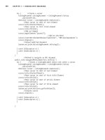
by informally introducing key terms. Figure 42.1 depicts entity relationships to support our
discussions.
492
Chapter 42 System Configuration Identification
Configuration Items
HWCIs CSCIs
AFP
Items
COTS
Products
NDI
Products
Integrated
into 1 *
Integrated
into 1 *
Integrated into 1 *
Consist of
1 *
Consist of
1 *
Consist of
1 *
Consist of 1 *
Consist of
1 *
Where:
AFP = Acquirer/User Furnished Property
CSC = Computer Software Component
CSU = Computer Software Unit
COTS = Commercial-Off-the-Shelf
CSCI = Computer Software Configuration Item
HWCI = Hardware Configuration Item
NDI = Non-Developmental Item
System Architectural
Configuration
Comprise
Items
Consist of 1 *
Internally
Developed,
Reusable
Components
CSCs CSUs
Integrated into 1 *
Where: = May or may not consis
t of
= Composition
Figure 42.1 System Configuration Identification Elements
Simpo PDF Merge and Split Unregistered Version -
Component Origins
Every entity within a SYSTEM, regardless of level of abstraction is referred to as an ITEM. If you
analyze most systems, you will discover that items originate from at least six different methods:
1. Procured from a vendor’s catalog.
2. Procured from a vendor’s catalog and customized/adapted in-house.
3. Customized or modified versions of items found in a vendor’s catalog.
4. Developed in-house by human intellect or procured as components or raw materials from
suppliers.
5. Developed in-house from customizations of existing, legacy designs.
6. Provided by the Acquirer in accordance with the terms and conditions (Ts&Cs) of the system
development contract and integrated into the SYSTEM design.
Observe two types of themes above. First, items are procured externally, and second, items are
developed internally.
Externally Acquired or Procured Components
As introduced in Chapter 41, items procured from a vendor’s catalog are referred to as commer-
cial off-the-shelf (COTS) items. COTS items customized or modified for a specific application are
referred to as nondevelopmental items (NDIs). Acquirer provided items are referred to as Acquirer
furnished property (AFP).
Author’s Note 42.1 When the System Developer receives contract-based AFP from the User
via the Acquirer, each item must be recorded, tracked, and controlled in accordance with the terms
and conditions (Ts&Cs) of the contract. Planned modifications to AFP typically require authori-
zation by the Acquirer’s Contracting Officer (ACO). Make sure the Ts&Cs clearly delineate WHO
is accountable for:
1. Providing AFP documentation.
2. AFP failures while in the possession of the System Developer.
Configuration Items (CIs)
When a System Developer decides to develop a MAJOR item such as a PRODUCT, SUBSYS-
TEM, or ASSEMBLY in-house, the program designates the item as a configuration item (CI). CIs
require a specification that specifies and bounds the CI’s capabilities and performance.
A CI, as a major item, integrates lower level components that may consist of: AFP, COTS
items, NDIs, and two other types developed by the System Developer in-house:
• Hardware configuration items (HWCIs)
• Computer software configuration items (CSCIs)
HWCIs and CSCIs
HWCIs are major hardware items and CSCIs are major software applications designated for con-
figuration control.
• As CIs, HWCIs and CSCIs may include COTS items, NDIs, internally developed or legacy
items, or combinations of these.
42.2 Understanding Configuration Identification Semantics 493
Simpo PDF Merge and Split Unregistered Version -
• Each HWCI is specified via requirements documented in an HWCI Requirements Specifica-
tion (HRS).
• Each CSCI is specified via requirements docuemented in a CSCI Software Requirements
Specification (SRS).
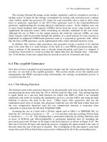
Firmware
Some processor-based applications such as single board computers (SBC) employ software encoded
into an integrated circuit (IC) referred to as firmware. Firmware ICs, which are nonvolatile memory
device types, may be implemented with single-use, read only, and reprogrammable devices.
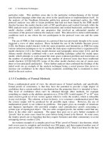
Firmware represents a hybrid instance of an item that evolves from a CSCI into an HWCI, as illus-
trated in Figure 42.2.
Initially, the software program executed by the SBC is developed as a CSCI software appli-
cation and debugged on laboratory prototype SBC hardware, using emulators and other devices.
When the software application reaches maturity and is ready for final integration, the CSCI’s code
is electronically programmed into the firmware IC device. Once programmed, the firmware IC is:
1. Designated as an HWCI.
2. Assigned a part number, serial number, and version.
Both the CSCI and HWCI are controlled in accordance with the CM procedures.
Guidepost 42.1 The preceding discussions introduced the semantics of configuration identifi-
cation. Some of these semantics apply to ANY level of abstraction. You should recall from our dis-
cussion in Chapter 9 System Levels of Abstraction and Semantics that one organization’s
SUBSYSTEM might be another organization’s SYSTEM. Our follow-on discussions illustrate WHY
the referential nature of configuration identification semantics when applied to levels of abstrac-
tion result in confusion.
Configuration Semantics Synthesis
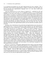
To understand how configuration identification semantics relate to multi-level system architectures,
Figures 42.1 and 42.3 depict the entity relationships. Table 42.1 provides a listing of entity rela-
tionship rules that govern the implementation of this graphic.
494
Chapter 42 System Configuration Identification
Computer
Software
Configuration
Item (CSCI)
Computer
Software
Configuration
Item (CSCI)
Hardware
Configuration
Item (HWCI)
Hardware
Configuration
Item (HWCI)
XXX-YYYY-2
Firmware
Programming
Device
Figure 42.2 Evolution of Firmware from Software to Hardware
Simpo PDF Merge and Split Unregistered Version -
42.2 Understanding Configuration Identification Semantics 495
SYSTEM
SYSTEM
SUBSYSTEM
s
SUBSYSTEMs
ASSEMBLY(s
)
ASSEMBLY(s)
SUBASSYs.
SUBASSYs.
PART
s
PARTs
Item
Item
Commercial-
Off-the-Shelf
(COTS) Item(s
)
Commercial-
Off-the-Shelf
(COTS) Item(s)
Non-
Developmental
Item
s (NDIs)
Non-
Developmental
Items (NDIs)
Configuration
Items (CIs
)
Configuration
Items (CIs)
HWCI(s
)
HWCI(s)
CSCI(s
)
CSCI(s)
Operational
Solution
Behavioral
Solution
Physical
Solution
Requirements
Solution
Where:
Consists of
Consists of
Consists of
Designated
as
Consists
of
Consists
of
= May or May Not
Designated
as
Designated
as
Designated
as
Designated
as
Solution Set
Described
by
Described
by
Consists
of
Consists of
PRODUCTs
PRODUCTs
Designated
as
Acquirer
Furnished
Equipment
(AFE
)
Acquirer
Furnished
Equipment
(AFE)
Figure 42.3 Item/Configuration Items (CIs) Compositional Entity Relationships
Table 42.1 Configuration semantics rules
Rule Title Configuration Identification and Development Rule
42.1 Items Every entity within a system, regardless of level of abstraction, is referred to as
an item.
42.2 Configuration Designate major items selected for internal development and configuration
items control.
42.3 Configuration Items may originate from several types of sources:
items 1. Replicated from existing, internally developed component designs.
2. Acquired as COTS, NDI, or AFP.
3. Acquired as COTS, NDI, or AFP and modified in-house.
4. Developed as new designs such as an HWCI(s) or CSCI(s).
42.4 CI A CI’s composition may consist of one or more COTS products, NDIs, HWCIs,
composition CSCIs, AFPs, or combinations thereof.
42.5 CI Develop a performance or development specification for each item designated as a
specifications CI.
42.6 HWCIs and Develop an HWCI Requirements Specification (HRS) for each HWCI; Develop a
CSCIs CSCI Software Requirements Specification (SRS) for each CSCI.
42.7 CI solution Develop a Requirements Domain, Operations Domain, Behavioral Domain, and
set Physical Domain Solutions for each CI, HWCI, and CSCI.
42.8 CSCIs The product structure of each CSCI consists of at least two or more CSCs that
consist of at least two or more CSUs.
42.9 CI ownership Assign accountability for the design, development, and integration and
verification for each CI, HWCI, and CSCI to an individual or IPT.
Simpo PDF Merge and Split Unregistered Version -
Guidepost 42.2 At this juncture we have established the context and composition of CIs. The
question is: HOW do we determine which items should be designated as CIs. This brings us to our
next topic on the selection of configuration items.
Selection of Configuration Items (CIs)
The preceding discussions established that CIs are MAJOR items developed in-house. While this
is an important criterion, CIs often require additional considerations. The best approach for select-
ing CIs is to simply establish a set of selection criteria. Then, perform a reasonableness check to
ensure that the selection:
1. Is logical.
2. Provides the proper visibility for technical, cost, and schedule tracking.
3. Exposes development activities at a level that can be used for assessing risk.
Some organizations establish specific criteria for selecting CIs that go beyond simply deciding to
develop an item internally. These decisions should be made in collaboration with a program’s con-
figuration manager, a subject matter expert (SME) in this domain.
The selection of configuration items often varies from one organization or business domain to
another. To standardize thinking about selecting CIs, MIL-STD-483A (cancelled) offers the fol-
lowing guidance in selecting CIs:
1. Is it a critical high risk, and/or a safety item?
2. Is it readily identifiable with respect to size, shape, and weight (hardware)?
3. Is it newly developed?
4. Does it incorporate new technologies?
5. Does it have an interface with hardware or software developed under another contract?
6. With respect to form, fit, or function, does it interface with other configuration items whose
configuration is controlled by other entities?
7. Is there a requirement to know the exact configuration and status of changes to it during
its life cycle?
(Source: Former MIL-STD-483A, para. 170.9, pp. 118–119)
Configuration Item (CI) Boundaries
Contrary to some beliefs, items and CIs SHOULD NOT be partitioned across physical device
boundaries; this is a violation of good design practice as noted in our earlier discussion of Figure
40.4. In general, CIs:
1. Are bounded by a development specification, HWCI Requirements Specification (HRS) or
CSCI Requirements Specification (SRS).
2. Reside within the boundaries of a physical item—such as SYSTEM, SUBSYSTEM,
ASSEMBLY, or SUBASSEMBLY as a computer system, printed circuit board, software
application, and so forth.
3. Must be verified against their respective HRS or SRS.
To illustrate this point, consider the hypothetical example below:
496 Chapter 42 System Configuration Identification
Simpo PDF Merge and Split Unregistered Version -
EXAMPLE 42.1
As an example of an INCORRECT approach, an organization has a contract to develop a word processor soft-
ware application. Using the INCORRECT approach, the software CSCI would have CSCs implemented across
physical items:
1. A desktop computer (HWCI)
2. The printer (HWCI)
3. Other (HWCIs) on a network
So, if CIs, HWCIs, and CSCIs require stand-alone performance or development specifications to
specify and bound an integrated item that is SELF-CONTAINED within a physical item, How do
we test the software, as an item, when it resides across several HWCIs (boundaries)?
Remember, CIs are tested and verified as standalone test articles—as a black box with inputs
and outputs—with all the necessary functionality self-contained. Adhering to the boundary con-
straints specified above, there is an expectation that the CSCI will be tested on a single HWCI
device such as a desktop computer. Obviously, this is not achievable since the CSCI’s CSCs are
implemented in several HWCI devices (desktop computer, printer, network, etc.) across the system.
The CORRECT approach requires a CSCI on each device.
Configuration Identification Responsibility
Configuration identification, as an informed, multi-discipline, decision-making process, requires
collaboration with those stakeholders. Contrary to what many people believe, it IS NOT a decision
by ONE individual exercising their discretionary authority in a vacuum without inputs from the
key decision stakeholders. As the multi-level entity architectures evolve, the Configuration Manager
(CM) / Software Configuration Manager (SCM), Lead SE, and other SEs collaborate to select the
CORRECT approach for identifying items and CIs that will endure the test of time and AVOID the
junk heap of POOR decisions.
Guidepost 42.3 At this point we have established the basic set of configuration identification
semantics and how they are applied to multi-level system architectures. These discussions high-
lighted the need during internal development to prepare a development specification for each CI,
HWCI, and CSCI. For the first article on Developmental Configurations, this is a straightforward
process. Two key questions:
1. HOW are these specifications maintained for production systems that evolve over time as
new capabilities and refinements are added to established designs?
2. How do these impacts affect systems or products that are already fielded that may require
RETROFITTING?
This brings us to our next topic, configuration effectivity.
Configuration Effectivity
Production systems may evolve over several years as newer technologies, capabilities, and improve-
ments are incorporated into the evolutionary system design solution. As such, the physical config-
uration changes. So the question becomes: HOW do we delineate the changes in configuration to
a given CI, HWCI, or CSCI? Configuration management addresses these configurations via a
concept referred to as configuration effectivity.
42.2 Understanding Configuration Identification Semantics 497
Simpo PDF Merge and Split Unregistered Version -
Every CI, HWCI, and CSCI is labeled with a unique identifier that delineates it from all others.
This occurs at two levels: 1) model number and 2) serial numbers. So, when physical configura-
tions change over the years, some organizations simply reference the effectivity beginning with
Serial Number (S/N) XXX; others append a “dash number” to the model number—such as Model
123456-1—to indicate a specific version. Most organizations today affix barcode labels to CIs,
HWCIs, and CSCIs to facilitate automated version or configuration tracking.
Versioning provides the System Developer a couple of options. It allows evolutionary track-
ing of a product line over its life span, and it provides a means to account for special customiza-
tions delivered to an Acquirer. In lieu of model numbers and versioning, some vendor’s employ
contract numbers and serial numbers to designate items.
You may ask: Why is this important to SE?
Effectivity-Based Specifications
During the development of a system or product, multi-discipline SEs prepare item development
specifications (IDSs) for PRODUCTS, SUBSYSTEMS, HWCIs, and CSCIs that form the Devel-
opmental Configuration. Although cost is a key constraint, most first article systems or products
MAY NOT represent the most cost-effective solution due to schedule and other constraints. First
articles are simply a solution that meets specification requirements. Typically, each deliverable is
assigned contract/model numbers and serial numbers.
If a system is planned for production, Product Engineering initiates efforts to reduce the recur-
ring per unit cost via design improvements, component and material selection and procurement,
manufacturing methods, and so forth. Ultimately, the improvements culminate in a revised item
development specification with effectivity beginning with S/N XXX forward.
Once production starts, CIs, HWCIs, and CSCIs evolve over time. Whereas during the origi-
nal system development, revisions to the Developmental Configuration specifications were issued
when changes occurred. So, when production item changes occur, you have to revise the specifi-
cation level and the effectivity.
When this occurs, the program has two choices: create a new specification unique to a
configuration, or designate model and serial number effectivity on the cover page and annotate
specification requirements unique to the effectivity within the document.
42.3 ALIGNING ITEMS AND CIs WITH
THE SPECIFICATION TREE
Once CIs are identified, the key question is: HOW do you communicate their location within the
system’s product structure? The answer is: CIs should be explicitly identified in the specification
tree based on derivation from the system architecture as shown in Figure 42.4.
Here, the SEIT analyzes the System Performance Specification (SPS) requirements to create
the SYSTEM level architecture, as shown in the lower left corner of the graphic. The architecture
consists of PRODUCTs A and B. PRODUCT B, which consists of ITEMs B_1 through B_3, will
be developed internally, and is designated as a CI.
As the system architecture evolves, the specification tree evolves, as shown on the right side
of the graphic. Based on the designation of CIs and items, item development specifications are
identified.
• PRODUCT A has its own PRODUCT A development specification.
• PRODUCT B, as a CI, has its own unique PRODUCT B development specification that
includes requirements for ITEMs B_1 through B_3.
498
Chapter 42 System Configuration Identification
Simpo PDF Merge and Split Unregistered Version -
• ITEM B_3 is designated as a CI for development and, as such, is required to have its own
unique ITEM B_3 development specification.
42.4 ASSIGNING OWNERSHIP OF ITEMS AND CIs
As the specification tree evolves, CI development ACCOUNTABILITY should be assigned to
owners such as development teams or Integrated Product Teams (IPTs). Figure 42.5 provides an
illustrative example. Note how the system architecture decomposes along product structure lines.
This is a key point, especially the operative word “product.”
For programs that establish Integrated Product Teams (IPTs), each IPT focuses on “product”
development and collaborates with interfacing IPTs developing items that interface to their assigned
product. For example, IPT 1 collaborates with IPT 2 on mutual interface design issues.
Accountability for developing ONE product is assigned to ONE and only one IPT. Depending
on the size, complexity, and risk of the multi-level items, an IPT may be assigned accountability
for one or more products as illustrated in Figure 42.5. Accountability for developing PRODUCTs
A and B, which have a moderate degree of complexity and risk, is assigned to IPT 1. In contrast,
accountability for PRODUCT C is assigned to IPT 2 due to its complexity and risk. This brings us
to a final point.
Programs often get into trouble because SEs develop the IPT organizational structure first and
then leave the IPTs to identify the architectural configuration with limited, if any, oversight by the
SEIT. In this example, PRODUCTs A and B, by virtue of accountability by IPT 1 would be bundled
together, regardless of the lack of physical interfaces and be idenitified as a PRODUCT or SUB-
SYSTEM. Then, the IPT will attempt to develop a development specification for the conglomeration.
In many cases PRODUCTs A and B are unrelated, thereby indicating NO interfaces. Yet, the
IPT will be required to verify both PRODUCTs together as a “black box.” Avoid and correct these
system configuration identification decisions. Often these decisions are made by local “heroes” with
42.4 Assigning Ownership of Items and CIs 499
System
Performance
Specification
(SPS
)
PRODUCT B
Configuration Item
PRODUCT B
Configuration Item
ITEM
B_1
COTS
ITEM
B_1
COTS
ITEM
B_2
COTS
ITEM
B_2
COTS
SYSTEM
SYSTEM
SYSTEM CI Product Structure
PRODUCT A
COTS Item
PRODUCT A
COTS Item
ITEM B_1
COTS Item
ITEM B_1
COTS Item
ITEM B_2
COTS Item
ITEM B_2
COTS Item
PRODUCT A
COTS Item
PRODUCT A
COTS Item
PRODUCT B
Configuration Item
SYSTEM Level Architecture
PRODUCT
A
Development
or Product
Specificatio
n
PRODUCT
B
Development
Specificatio
n
Item B_3
Configuration
Item
Item B_3
Configuration
Item
ITEM B_3
Configuration
Item
ITEM B_3
Configuration
Item
PRODUCT
B_3
Development
or Product
Specificatio
n
3
Figure 42.4 System Configuration Documentation
Simpo PDF Merge and Split Unregistered Version -
an ounce of knowledge about system architecture development and IPT implementation yet wield
authority and create programmatic situations that severely impact contract performance.
42.5 RECOGNIZING TYPES OF
ARCHITECTURAL ITEM BOUNDARIES
The Industrial Revolution introduced new concepts for standardizing and reproducing modular and
interchangeable components via predictable methods in order to leverage the benefits of economies
of scale. Our discussions on SYSTEM, PRODUCT, SUBSYSTEM, ASSEMBLY, SUBASSEM-
BLY, and PART levels of abstraction expound on these themes.
The concept of modularity can easily lead to the SE mindset that all items and CIs are con-
structed as modular plug and play boxes. The System of Systems (SOS) approach further reinforces
the mindset of “box” CIs integrated into a higher level system. However, there are systems whereby
INTEGRATION occurs ACROSS the traditional “box” boundaries.
In general, systems often consist of two classes of PRODUCTs/SUBSYSTEMs:
1. Mission specific PRODUCTs/SUBSYSTEMS.
2. Infrastructure PRODUCTs/SUBSYSTEMS that transcend the mission-specific SUBSYS-
TEM boundaries.
Figure 42.6 illustrates this type of architecture. Consider the following example:
EXAMPLE 42.2
Office building systems, as MISSION SYSTEMs, consist of well-defined architectural “box” boundaries. Hier-
archically, we could refer to the individual floors of office buildings as SUBSYSTEM level CIs. However,
what about the plumbing and electrical, heating, ventilation, and air conditioning (HVAC) system CIs that
500 Chapter 42 System Configuration Identification
Configuration
Item Hierarchy
PRODUCT B
Configuration Item
PRODUCT B
Configuration Item
ITEM
B_1
ITEM
B_1
ITEM
B_2
ITEM
B_2
SYSTEM
SYSTEM
PRODUCT A
Configuration
Item
PRODUCT A
Configuration
Item
ITEM B_3
Configuration
Item
ITEM B_3
Configuration
Item
PRODUCT C
Configuration Item
PRODUCT C
Configuration Item
ITEM
C_1
ITEM
C_1
ITEM
C_2
ITEM
C_2
IPT #1
IPT #2
CI A Lead
ITEM B_1 Lead
ITEM B_2 Lead
CI B_3 Lead
ITEM C_1 Lead
ITEM C_2 Team Lead
IPT #1 Lead
IPT #2 Lead
IPT
Responsibility &
Accountability
IPT #1 Accountability IPT #2 Accountability
Figure 42.5 CI Assigned Responsibility & Accountability
Simpo PDF Merge and Split Unregistered Version -
TRANSCEND all of the floors and office boundaries? We can declare the floors and offices as mission-based
SUBSYSTEMS. Infrastructure SUBSYSTEMS such as HVAC systems, would plumbing, electrical, and other
such systems, transcend each floor.
Systems such as aircraft and automobiles, exhibit similar configurations. Fuel systems and electri-
cal systems, for example, traverse the entire structure.
Relevance to SE
Now you are probably asking: WHY IS this relevant to SE? After all, this is simply a means of cre-
ating a SYSTEM architecture. The importance of this point is estimating the cost of a system during
the System Procurement Phase. SEs must:
1. Recognize the existence of mission-specific and cross-cutting infrastructure systems.
2. Appreciate the need to establish a consensus on system configuration boundaries and delin-
eate WHAT IS/IS NOT included within each mission-specific and infrastructure boundary
via a CWBS Dictionary that scopes the contents.
The focal point for organizing cost estimating efforts, establishing work performance benchmarks,
and measuring planned versus actual work progress is the Contract Work Breakdown Structure
(CWBS). As we have reiterated numerous times, the CWBS, especially its Mission Equipment
Element, should be derived from the SYSTEM’s architecture. Unfortunately, most organizations
do just the reverse. They haphazardly create the CWBS and then try to contort the system archi-
tecture to match the flawed CWBS!
Returning to our office building example, HOW do you estimate costs on the basis of:
1. Hierarchical categories of rooms with embedded plumbing, electrical, HVAC, and struc-
tural components?
42.5 Recognizing Types of Architectural Item Boundaries 501
Power Distribution
SUBSYSTEM
(Configuration Item)
Power Distribution
SUBSYSTEM
(Configuration Item)
Communications
SUBSYSTEM
(Configuration Item)
Communications
SUBSYSTEM
(Configuration Item)
HVAC
SUBSYSTEM
(Configuration Item)
HVAC
SUBSYSTEM
(Configuration Item)
SYSTEM
SYSTEM
Fire Protection
SUBSYSTEM
(Configuration Item)
Fire Protection
SUBSYSTEM
(Configuration Item)
Offices
SUBSYSTEM
(Configuration Item)
Offices
SUBSYSTEM
(Configuration Item)
Laboratory
SUBSYSTEM
(Configuration Item)
Laboratory
SUBSYSTEM
(Configuration Item)
Laboratory
SUBSYSTEM
(Configuration Item)
Laboratory
SUBSYSTEM
(Configuration Item)
Where:
HVAC = Heating, Ventilation, & Air Conditioning
Infrastructure
SUBSYSTEMS
Mission-Specific
SUBSYSTEMS
Figure 42.6 System Configuration Identification with Cross-Cutting Cis
Simpo PDF Merge and Split Unregistered Version -
2. Hierarchical mission-specific rooms and separate infrastructure structural, electrical, plumb-
ing, and HVAC systems?
For systems such as buildings, homes, and aircraft, the CWBS Dictionary scopes infrastructure
systems such as structural, electrical, plumbing, HVAC, and communications as separately cost ac-
countable CWBS elements. This is driven by that fact that for electrical, plumbing, HVAC, network,
and audio-visual communications elements, there are contractors who specialize in these areas.
Contemplate what would happen if we structured the CWBS to merge home construction
mission-specific and infrastructure SUBSYSTEMs. The foyer, living room, kitchen, and bedroom
SUBSYSTEMs would include internal electrical, mechanical, and plumbing elements. By this
approach, from a verification perspective, each of these SUBSYSTEMS would be individually
inspected and verified. Now imagine what would happen if you called the building inspectors to
“inspect and verify” the HVAC, electrical, and structural elements of the Dining Room SUBSYS-
TEM and called them back a week later to verify the same elements of the Family Room SUB-
SYSTEM. The approach is FLAWED!
The bottom line is: decompose your system into a hierarchy of logical/behavioral and physi-
cal elements that can be specified, developed, procured, integrated, and verified with minimal sets
of interdependencies. Recognize that some PRODUCTs/SUBSYSTEMs are mission-specific;
others are infrastructure SUBSYSTEMs that transcend mission-specific SUBSYSTEMS. Structure
the CWBS to accommodate not only the SYSTEM architecture but also cost estimating and con-
tracting efforts.
Additionally, this approach enables separate specifications for infrastructure CIs that can be
easily subcontracted out to vendors who specialize in those areas. If the infrastructure entities
were embedded within a mission-specific CI, SEs would have to partition out requirements for
infrastructure entities and create separate procurement specifications. The extra work is simply
unnecessary.
42.6 MULTIPLE INSTANCES OF CI IMPLEMENTATION
Although we tend to think that every item in a system is unique, systems and products often have
multiple instances of a single CI throughout the system. One of the roles of SE and the SEIT is to
reduce development cost, schedule, and risk. You do this by investigating the evolving system
design solution and searching for opportunities to STANDARDIZE components and interfaces. The
bottom line is: AVOID REINVENTING THE WHEEL by creating specialized CI designs that can
be satisified by one common CI design.
42.7 CONFIGURATION BASELINES
System development, as evidenced by previous discussions, requires translation of abstract System
Performance Specification (SPS) requirements into a physical solution. The translation decomposes
or expands abstract complexity into more manageable lower levels of detail. Ultimately, a detailed
design matures to a point whereby design requirements such as drawings and software design are
sufficient in detail to support procurement, fabrication, and coding of all items in the SYSTEM.
Lower levels of design decisions, as refinements of higher level decisions, are totally depend-
ent on maturing stability of the higher level design decisions. Otherwise, the entire solution evolves
into multi-level chaos. So, as higher level decisions stabilize, it is important to capture and control
the state of the evolving solution referred to as the Developmental Configuration.
502
Chapter 42 System Configuration Identification
Simpo PDF Merge and Split Unregistered Version -
The Developmental Configuration
The Developmental Configuration is characterized by a series of configuration “snapshots” that
capture the evolving system design’s solution at various stages of maturity. Each configuration
enables SEs to maintain intellectual control of the evolving and maturing system design’s solution
by controlling changes to the configuration. Therefore, the scope of the Development Configura-
tion spans the time period from Contract Award until a system is committed to production.
From an SE perspective, there are six types of configuration classifications as listed below that
represent a level of maturity at various stages of development.
Stage 1: “As Specified” Configuration
Stage 2: “As Allocated” Configuration
Stage 3: “As Designed” Configuration
Stage 4: “As Built” Configuration
Stage 5: “As Verified” Configuration
Stage 6: “As Validated” Configuration
Stage 7: “As Maintained” Configuration
Stage 8: “As Produced” Configuration
Let’s briefly synopsize each of these SE configurations.
• “As Specified” Configuration Represents the state of the SPS and lower level specifica-
tions as captured and maintained via the System Requirements Baseline.
• “As Allocated” Configuration Represents the allocation of requirements from the System
Requirements Baseline specifications to items.
• “As Built” Configuration Represents the state of the Developmental Configuration for first
articles at any level of abstraction prior to formal verification. Generally, the “As Built” Con-
figuration employs serial number effectivity configuration control methods to match the phys-
ical system to its “As Designed” Configuration.
• “As Designed” Configuration Represents the current, approved Developmental Configu-
ration baseline derived from the “As Specified” Configuration or System Requirements Base-
line. The “As Designed” Configuration is initially captured at the System Design Review
(SDR) and maintained to incorporate any change modifications to the baseline.
• “As Verified” Configuration Represents the state of the physical SYSTEM at completion
of its formal System Verification Review (SVR) in which the “As Specified,” “As Designed,”
and “As Built” Configurations mutually agree with each other and comply with specification
requirements.
• “As Validated” Configuration Represents the state of the physical system as VALIDATED
by the User, or an Independent Test Agengy (ITA) representing the user, during the
Operational Test and Evaluation (OT&E) under prescribed field operating environments and
conditions.
• “As Maintained” Configuration Represents the state of the physical system configuration
that is currently operated and maintained by the User in the field. From an SE and a con-
figuration management perspective, the FAILURE to keep the “As Maintained” Configura-
tion documentation current is a MAJOR RISK area, especially for developmental systems
planned for production.
42.7 Configuration Baselines 503
Simpo PDF Merge and Split Unregistered Version -
• “As Produced” Configuration Represents the state of the Production Baseline used to man-
ufacture the system or product in production quantities.
Author’s Note 42.2 The “As Maintained” Configuration is a crucial point for SE. It documents
the configuration of the fielded operational system(s). It is not uncommon for the User to become
LAX due to the lack of initiative or budgets in maintaining the “As Maintained” Configuration doc-
umentation. The result is a physical system or product that DOES NOT identically match its con-
figuration documentation, which is a MAJOR risk factor for the System Developer.
Developmental Configuration Staging or Control Points
As the Developmental Configuration evolves through a series of design and development stages,
it is important to establish agreement among the Acquirer, User, and System Developer about the
evolving and maturing system design solution. Depending on the type of contract and WHAT pro-
visions each party has in the decision-making process, we do this via staging or control points.
Staging or control points, which consist of major technical review events, are intended to rep-
resent stages of maturity of the evolving system design solution as it advances into lower levels of
abstraction or detail over time. We do this via a series of Configuration Baselines.
From a configuration management perspective, there are four configuration baselines:
• System Requirements or Functional Baseline
• Allocated Baseline
• Product Baseline
• Production Baseline
Note that our discussions identified two perspectives of the evolving and maturing Develop-
mental Configuration: 1) an SE configuration perspective and 2) a configuration management per-
spective. Despite the semantics both sets correlate as illustrated in Table 42.2.
42.8 GUIDING PRINCIPLES
In summary, the preceding discussions provide the basis with which to establish the guiding prin-
ciples that govern system configuration identification practices.
Principle 42.1 Every component in a SYSTEM is an item. Some are designated as configura-
tion items (CIs) for internal development; others as commercial off-the-shelf (COTS) items or
nondevelopmental items (NDIs) for external procurement.
Principle 42.2 Development of a configuration item (CI) should only occur when all other
COTS/NDI alternatives have proved to be impractical, not cost effective, or noncompliant with
technical, cost and schedule requirements.
Principle 42.3 Every SYSTEM/Entity has seven SE design configurations—As Specified, As
Designed, As Built, As Verified, As Validated, As Maintained, and As Produced—that must be
current and consistent.
Principle 42.4 Every SYSTEM has three primary Developmental Configuration Baselines: 1) a
System Requirements or Functional Baseline, 2) a Allocated Baseline, and 3) a Product Baseline.
Systems in production have a Production Baseline.
504
Chapter 42 System Configuration Identification
Simpo PDF Merge and Split Unregistered Version -
Principle 42.5 As a contract element, the Acquirer owns and controls the System Performance
Specification (SPS); the System Developer maintains the SPS in accordance with the contract direc-
tion authorized and provided by the Acquirer Contracting Officer (ACO).
42.9 SUMMARY
During system configuration identification discussions, we addressed how various elements of the EQUIP-
MENT system element are designated via a set of semantic terms. These are the terms that SEs use as a
common language to communicate. The intent is to enable the recipient to understand the context of each
application.
GENERAL EXERCISES
1. Answer each of the What You Should Learn from This Chapter questions identified in the Introduction.
2. Refer to the list of systems identified in Chapter 2. Based on a selection from the preceding chapter’s
General Exercises or a new system selection, apply your knowledge derived from this chapter’s topical
discussions. Specifically identify the following:
(a) Based on an analysis of the multi-level system architecture, which items would you designate as
configuration items?
(b) Which items might be procured as COTS or NDIs?
General Exercises
505
Table 42.2 Correlating SE configuration and CM baseline perspectives
Staging or Control Point SE Configuration CM Baselines
Perspective
System Requirements Review (SRR) As Specified (system) System Entity Requirements
or Functional Baseline
System Design Review (SDR) As Allocated Allocated Baseline
As Designed
(system/subsystem)
Hardware Specification Review (HSR) As Specified (HWCIs)
Software Specification Review (SSR) As Specified (CSCIs)
Preliminary Design Review (PDR) As Designed (HWCIs/CSCIs)
Critical Design Review (PDR) As Designed
Completion of Component As Built
Procurement and Development
Test Readiness Reviews (TRRs) As Verified (components)
System Verification Review (SVR) As Verified (system) Product Baseline
Formal Qualification Review (FQR) As Validated (system)
Pre-Production Readiness Review (PPRR) As Maintained
Production Readiness Review (PRR) As Produced Production Baseline
Simpo PDF Merge and Split Unregistered Version -
ORGANIZATIONAL CENTRIC EXERCISES
1. Research your organization’s command media. Identify what requirements are levied by the organization
on programs regarding CIs, HWCIs, CSCIs, COTS, and NDIs?
2. Contact an internal contract program. Inquire as to how items, CIs, HWCIs, CSCIs, COTS, and NDIs are
implemented in the program.
(a) Does the contract specify criteria for selecting CIs?
(b) Correlate CIs, HWCIs, and CSCIs with the specification tree.
(c) Report your findings and observations.
3. For the contract program noted above, investigate how firmware is developed, managed, and
controlled.
4. Research Internet sites for instances of how other organizations specify and control CIs, HWCIs, CSCIs,
COTS, NDIs, and firmware.
REFERENCES
506 Chapter 42 System Configuration Identification
ANSI/EIA-649-1998. 1998. National Consensus Standard
for Configuration Management, Electronic Industries
Alliance (EIA). Arlington, VA
IEEE Std 610.12-1990. 1990. IEEE Standard Glossary of
Modeling and Simulation Terminology. Institute of Elec-
trical and Electronic Engineers (IEEE). New York, NY.
Defense Systems Management College (DSMC). 2001.
Glossary: Defense Acquisition Acronyms and Terms, 10th
ed. Defense Acquisition University Press Ft. Belvoir, VA.
MIL-STD-483A (canceled). 1985. Configuration Manage-
ment Practices for Systems, Munitions, and Computer
Programs. Washington, DC: Department of Defense.
MIL-STD-498 (canceled). 1994. Software Development and
Documentation. Washington, DC: Department of Defense
(DoD).
MIL-STD-973 (canceled). 1992. Configuration Manage-
ment. Washington, DC: Department of Defense (DoD).
ADDITIONAL READING
DI-IPSC-8 1448A, 1999. DoD Data Item Description (DID).
Firmware Support Manual (FSM). Washington, DC:
Department of Defense (DoD).
MIL-HDBK-61. 1997. Configuration Management Guid-
ance. Washington, DC: Department of Defense (DoD).
Federal Aviation Administration (FAA), ASD-100 Architec-
ture and System Engineering. National Air Space
System—Systems Engineering Manual. Washington, DC:
FAA.
Simpo PDF Merge and Split Unregistered Version -
Chapter 43
System Interface Analysis,
Design, and Control
43.1 INTRODUCTION
The identification, design, and control of system interfaces are key activities for system architec-
ture development. The capability of the SYSTEM and item interfaces to cooperatively or defen-
sively interact and interoperate with external systems within the context of their OPERATING
ENVIRONMENT often determines mission survival and success.
Our discussion expands that of Chapter 12, System Interfaces, into HOW SEs translate abstract
interface requirements into specification requirements. Based on those requirements, analytical, sci-
entific, engineering, and management principles enable SEs to design the interface. The foundation
for interface design builds on our discussions of Chapter 8 The Architecture of Systems and Chapter
21 System Operational Capability Derivation and Allocation.
We continue our discussion of generalized and specialized interfaces, define an interface design
methodology, investigate system ownership and control, address the need for standardization, and
define how interfaces are documented. We conclude with a discussion of the challenges and issues
in defining the system interfaces.
What You Should Learn from This Chapter
1. How are interfaces identified for and within a SYSTEM?
2. How do you analyze interface interactions?
3. How is the System Capability Construct applied to interface design?
4. What is the methodology for designing interfaces?
5. Who owns and controls SYSTEM and item interfaces at various levels of abstraction?
6. What is an Interface Requirements Specification (IRS)?
7. What is an Interface Control Document (ICD)?
8. What is an Interface Design Description (IDD)?
9. How do you decide to develop and IRS, ICD, and/or IDD?
10. What is an Interface Control Working Group (ICWG)?
11. Who chairs the ICWG?
12. What are some rules for analyzing, designing, and controlling SYSTEM or entity
interfaces?
System Analysis, Design, and Development, by Charles S. Wasson
Copyright © 2006 by John Wiley & Sons, Inc.
507
Simpo PDF Merge and Split Unregistered Version -
Definitions of Key Terms
• Compatibility Refer to the definition provided in Chapter 15 System Interactions with Its
Operating Environment.
• Coupling “The manner and degree of interdependence between software modules. Types
include common-environment coupling, content coupling, control coupling, data coupling,
hybrid coupling, and pathological coupling.” (Source: IEEE 610.12-1990)
• Interface Control Refer to the definition provided in Chapter 12 System Interfaces.
• Interface Ownership The assignment of accountability to an individual, team, or organi-
zation regarding the definition, specification, development, control, operation, and support
of an interface.
• Line Replaceable Unit (LRU) Refer to definition in Chapter 42 on System Configuration
Identification Practices.
43.2 IDENTIFYING AND ANALYZING
INTERFACE INTERACTIONS
Once logical entity relationships between the SYSTEM and external systems or between internal
items are identified, the next step is to analyze and bound the interactions. In Chapter 12, System
Interfaces, we noted that physical interfaces can be characterized as mechanical, electrical, optical,
acoustical, environmental, chemical, biological, and nuclear. The question is: How do we specify
and bound the operational and physical characteristics of the interface. Let’s answer each part of
this question separately.
Specifying and Bounding Interface Operational Characteristics
Interface operational characteristics are derived using UML
®
sequence diagrams as illustrated in
Figure 17.3. These diagrams, coupled with a Mission Event Timeline (MET), provide analytical
insights into HOW the interfacing entities interact and interoperate.
Specifying and Bounding Interface Physical Characteristics
Analysis of interacting systems requires investigation of a variety of classes of interactions. For
most systems the classes of interfaces include:
• Electrical
• Mechanical
• Optical
• Chemical
• Biological
• Acoustical
• Human
• Mass Properties
508 Chapter 43 System Interface Analysis, Design, and Control
Simpo PDF Merge and Split Unregistered Version -
One of the challenges of physical interface analysis is that SEs and analysts become intrigued and
immersed by a specific class of interaction and tend to overlook or ignore other classes that may
become SHOWSTOPPERS. One method of analyzing interfaces employs a matrix approach as
illustrated in Figure 43.1.
Author’s Note 43.1 The matrix provides a framework for illustrating the thought processes
required to understand all of the performance effecters that influence design considerations. Based
on these thought processes, your job as a system analyst or SE is to determine which one(s) of the
effecters warrants consideration for specific SYSTEM applications.
The matrix maps interactions between a MISSION SYSTEM interface classes (rows) and the
OPERATING ENVIRONMENT interface classes (columns). Since both domains of system ele-
ments have comparable classes of interfaces, SEs divide each domain into the various categories.
Note also that the OPERATING ENVIRONMENT includes the NATURAL, INDUCED and
HUMAN-MADE SYSTEMS elements. To facilitate the analysis, we assign a unique identifier to
each interaction (row-column intersection).
Thus, for each interaction, at least one or more specification requirements are written to specify
and bound the interaction and the expected outcome and performance of each interaction. To illus-
trate this point, consider the following example:
EXAMPLE 43.1
In an environmentally controlled laboratory environment, electrical (class) interactions—such as electro-
magnetic radiation (EMI) and noise—are likely to occur and may have an effect on the test articles or
instrumentation. In contrast, chemical (class) interactions—such as salt spray—do not occur naturally in a
laboratory.
43.2 Identifying and Analyzing Interface Interactions
509
Electrical
Mechanical
Optical
Chemical
Mass Properties
Biological
Acoustical
Electrical
Mechanical
Optical
Chemical
Mass Properties
Biological
Acoustical
NATURAL Environmen
t
OPERATING ENVIRONMENT Interface Classes
MISSION SYSTEM
Interface Classes
MISSION
SYSTEM
MISSION
SYSTEM
OPERATING
ENVIRONMENT
OPERATING
ENVIRONMENT
1
INDUCED Environmen
t
HUMAN-MADE SYSTEM Interface Attributes
2 3 4 5 6 7 8 9
11 12 13 14 15 16 17 18 19
21 22 23 24 25 26 27 28 29
31 32 33 34 35 36 37 38 39
41 42 43 44 45 46 47 48 49
51 52 53 54 55 56 57 58 59
61 62 63 64 65 66 67 68 69
Huma
n
10
20
30
40
50
60
70
Huma
n
71 72 73 74 75 76 77 78 79 80
SYSTEM OF INTEREST (SOI)
Interface Attributes
Figure 43.1 SYSTEM OF INTEREST (SOI) Interface Interactions Analysis Matrix
Simpo PDF Merge and Split Unregistered Version -
Practical Realities
In theory, this approach seems logical; however, is it practical to develop an analysis such as this
within contract or task resource and time constraints? The answer depends on your situation. In
general, most seasoned SEs subconsciously imprint this analytical method into memory based on
personal experience. The challenge is assimilating all relevant interactions from memory without
overlooking any condition.
If your contract or task is resource and time limited, you might consider using a
template such as this as a quick checklist to identify the most likely or probable interactions. In
sharp contrast, some SYSTEMS may have inherent safety risks with potential consequences for
human health and safety, property, the environment, or survival of the enterprise. You and your
organization must weight the cost to perform and merits of this analytical task versus the legal,
financial, and other consequences of IGNORING ALL likely interface interactions in practical
terms.
Guidepost 43.1 Based on the preceding discussion, we have identified and characterized the
attributes of interface interactions. The question is: WHAT inherent SYSTEM or entity interface
capabilities and levels of performance are required to successfully:
1. Be compatible or interoperable with the external SYSTEMS or entities.
2. Avoid threat vulnerabilities related to these interactions?
This brings us to our next topic, understanding system interface design solutions.
43.3 GENERALIZED VERSUS SPECIALIZED
INTERFACE DESIGN SOLUTIONS
Physical interface solutions occur at two levels: 1) as generalized solutions and 2) as specialized
solutions. Generalized solutions represent a “first-pass” physical implementation that appears “on
the surface” to be adequate for most applications. There may be special circumstances that require
further interface design refinements or robustness; we refer to these specialized solutions. Let’s
explore each of these further.
Generalized Interface Solutions
Generalized interface solutions represent the analytical world whereby that analyst identifies a
logical entity relationship, association, or potential relationship between two entities such as a
MISSION SYSTEM and its OPERATING ENVIRONMENT. Consider the following example:
EXAMPLE 43.2
Analytically, a car has a potential logical entity relationship with other vehicles, trees, and people in its OPER-
ATING ENVIRONMENT. The recognition of this association is an acknowledgement that:
1. A physical relationship exists between the entities.
2. Further interface analysis must determine the level of significance and outcomes of the interactions to the
MISSION SYSTEM and, if necessary, on the interfacing entity—its vulnerability and survivability.
510 Chapter 43 System Interface Analysis, Design, and Control
Simpo PDF Merge and Split Unregistered Version -
Specialized Interface Solutions
Once a determination is made that a logical entity relationship exists between entities, the associ-
ations are analyzed to determine their effects on the interface and subsequently the MISSION
SYSTEM. Let’s return to the preceding car example.
EXAMPLE 43.3
Engineers determined many years ago that vehicles require front and rear bumpers. After many years of acci-
dents and federal mandates, automobile manufacturers upgraded bumper designs to include shock absorbers
that reduce the effects of impact with other vehicles and objects. Although the new bumpers solved one
problem, vehicle occupants continued to have the risk of injuries due to head-on crashes. Subsequently, seat
belts were added to vehicles. Although seat belts reduced injuries and saved lives, vehicle occupants contin-
ued to suffer life-threatening injuries. So, car designs incorporated air bag systems into the driver’s side of
the vehicle. Later air bags were added to protect the front seat passenger. Today additional specialized solu-
tions are being added to incorporate side impact air bags. New evidence indicates emergency medical serv-
ices (EMS) personnel have the potential risk of injury from air bag deployment while attending to accident
victims trapped in the wreck. So, specialized solutions to operational needs continue to evolve.
This example illustrates HOW a generalized solution representing a logical entity relationship
evolves into specialized solutions via physical design implementations.
Guidepost 43.2 Based on an understanding of generalized and specialized interfaces, we shift
our attention to HOW an interface is implemented.
43.4 APPLYING THE SYSTEM CAPABILITY
CONSTRUCT TO INTERFACES
As a prerequisite to our discussion here, revisit the key points noted in Chapter 22 The Anatomy
of System Capability. Figure 22.1 serves as a guide for our discussion.
The System Capability Construct provides a framework to describe HOW a system capability
such as an interface is:
1. Initiated.
2. Performs its mission—resulting in a product, service, or action.
3. Configures itself for repetitive cycle or dormancy until initiated again.
In performing these actions, an interface capability assesses health and readiness status, makes a
determination of degraded performance or failure conditions, reports those conditions, and attempts
to recover from those conditions.
43.5 INTERFACE DESIGN METHODOLOGY
Key elements of interface design practices can be summarized as a five-step methodology that fits
most applications. The steps are:
Step 1: Identify the SOI–OPERATING ENVIRONMENT relationships.
Step 2: Develop the SYSTEM or item architecture.
Step 3: Characterize the logical entity relationships of the architecture.
43.5 Interface Design Methodology 511
Simpo PDF Merge and Split Unregistered Version -
Step 4: Characterize the operational interface use cases.
Step 5: Characterize the physical interface characteristics.
Let’s address each of the steps of the methodology.
Step 1: Identify the SOI–OPERATING
ENVIRONMENT Relationships
The initial step of the methodology is to identify those entities within the User’s OPERATING
ENVIRONMENT that represent the interfaces relevant to the SYSTEM OF INTEREST (SOI).
Step 2: Develop the SYSTEM or Item Architecture
Construct the SYSTEM or entity architecture to depict its logical (associative) and/or physical rela-
tionships with external systems.
Step 3: Characterize the Logical Entity
Relationships of the Architecture
Based on the SYSTEM or entity architecture or validated User needs analysis, characterize the
logical entity relationships between internal and external entities—such as HUMAN-MADE
SYSTEMS and the OPERATING ENVIRONMENT. In general, this step formally describes the
interface.
Step 4: Characterize the Operational
Interface Use Cases
For each SYSTEM level or entity interface, identify the key operational characteristics of the
interface.
1. WHO are the interface stakeholders?
2. WHAT is to be exchanged across the interface—content, forces, and directional flow?
3. WHEN and HOW frequently is the interface to be employed—continuous or intermittent
connectivity?
4. WHERE is the interface to be employed?
5. HOW will the interface be controlled, security and privacy methods?
6. Under WHAT conditions is the interface to be employed?
Step 5: Characterize the Physical Interface Characteristics
Using the operational interface attributes as the basis, identify the key operational and physical
characteristics of the interface. For data communications interfaces, interface attributes include
connectors, pin-outs, wiring diagrams, grounding and shielding, protocol, timing and synchroniza-
tion, data formats, handshakes, addressing, encryption, and standards as noted in Table 43.1.
Step 6: Develop and Document the Interface Design Solution
As the operational, logical, and physical attributes of the interface are identified and
characterized, capture the results in an Interface Control Document (ICD) or Interface Design
Description (IDD). Document the design rationale, trade-offs, and so forth.
512
Chapter 43 System Interface Analysis, Design, and Control
Simpo PDF Merge and Split Unregistered Version -
43.6 SPECIFYING AND BOUNDING SYSTEM
INTERFACE REQUIREMENTS
Before we address specifying and bounding interface requirements, let’s establish WHERE and
HOW interface requirements are documented. Interface requirements are typically specified in the
System Interfaces section of a System Performance Specification (SPS) or item development spec-
ification; typically, Section 3.X. In some cases, software interface requirements may be specified
in an interface requirements specification (IRS).
43.6 Specifying and Bounding System Interface Requirements 513
Table 43.1 Interface attributes and descriptions
ID Attribute Attribute Description
43.1 Physical Characterize the interface in terms of its electrical, mechanical, optical, chemical,
Interface Type or environmental attributes.
43.2 Operational Identify the interface modes and states of operation such as STANDBY, POWER
States and OFF, stowed, and disconnected.
Modes
43.3 Directionality Determine the directionality of the interface for various modes of operation.
Some interfaces are unidirectional, bi-directional, etc.
43.4 Interface Investigate any protocol requirements to implement a specific protocol for
Protocol sending and receiving messages such as Identification Friend or Foe (IFF) and
standards.
43.5 Frequency of Determine the frequency of usage such as statistical distributions of usage during
Usage hours of operation, peak periods; asynchronous and synchronous
communications, etc.
43.6 Reserve Depending on the frequency of usage, some interfaces may require memory
Capacity storage to accommodate message buffering prior to transmission or after receipt
of messages. Electrical power and mechanical systems require similar analogies
to serve as design safety margins to sustain performance.
43.7 Strength Some data system interfaces separated by long distances impose minimum
electrical, mechanical, or optical strength requirements such as amplitude,
power, and pressure that require drivers to sustain signal strength.
43.8 Specialty Depending on technical risk, investigate interface specialty-engineering
Requirements requirements that include reliability, availability, maintainability, vulnerability,
survivability, etc.
43.9 Technology For some systems, characterize the interface technology such as laser, sensor,
data communications, chemical, and radiation.
43.10 Training Due to the nature of some interfaces, identify special training for operators and
maintainers.
43.11 Cost Assess WHAT level of capability you can provide within budgetary cost and
schedule constraints.
43.12 Risk Identify the level of risk associated with operating the interface including
probability of occurrence and consequences of failure.
Simpo PDF Merge and Split Unregistered Version -
The Interface Specification
What is an IRS? DoD Data Item Description (DID) DI-IPSC-81434 states “The Interface
Requirements Specification (IRS) specifies the requirements imposed on one or more systems, sub-
systems, Hardware Configuration Items (HWCIs), Computer Software Configuration Items (CSCIs),
manual operations, or other system components to achieve one or more interfaces among these
entities. An IRS can cover any number of interfaces The IRS can be used to supplement the
System/Subsystem Specification (SSS) and Software Requirements Specification (SRS) as the
basis for design and qualification testing of systems and CSCIs.” [Source: DoD Data Item Descrip-
tion (DID) DI-IPSC-81434, p. 1]
People ask: If the interface requirements are stated in the SPS or item development specifica-
tion, WHY do you need a separate interface specification? The answer has two contexts:
1. Interfaces external to the SYSTEM.
2. Interfaces internal to a SYSTEM.
Ideally, interface requirements for a SYSTEM should be documented in a single requirements
specification, preferably the SPS, or a lower level item development specification (IDS) for a con-
figuration item (CI). The answer to the question depends on:
1. WHAT your contract requires.
2. Other factors related to protecting System Developer sensitive data such as contract spec-
ifications, intellectual property, proprietary data, and security.
Contract Requirements for an Interface Specification
ALWAYS investigate and READ the Request for Proposal (RFP) and its Contract Data Require-
ments List (CDRL) regarding interface specification requirements, if any. If there are no IRS CDRL
items, incorporate interface requirements into the SPS or item development specification, depend-
ing on application. This avoids:
1. The necessity and expense of maintaining and verifying two separate documents—SPS/IDS
and an interface specification—with common boilerplate.
2. Coordinating separate document reviews and approvals.
From a system perspective, you want to VERIFY the system as an entity using one specification
with:
• One set of acceptance test procedures (ATPs).
• One Requirements Verification Matrix (RVM).
• One set of ATP data.
Simultaneously verifying requirements stated in TWO separate specifications compounds the tasks,
paperwork, and coordination. You may respond that you could have two specifications and a single
set of ATPs and ATP results. This is true, but you still have to account for HOW you can TRACK
these separate/combined results. This leads to WHY not specify all SYSTEM or entity interface
requirements in one document unless there is a compelling need to isolate the requirements in a
separate document. Keep it simple!
Is an IRS Necessary for Internal Development? No. In fact a common problem of many
programs is having ill-informed decision makers declaring in their proposal they will develop “an
IRS for EVERY external and internal interface.” This is naive, expensive, and unnecessary.
514 Chapter 43 System Interface Analysis, Design, and Control
Simpo PDF Merge and Split Unregistered Version -
There are, however, reasons—such as volume of requirements, data security classification, and
procurement reasons—for a separate IRS. By default, define the interface requirements in the SPS
or item development specification. Then, if there are compelling reasons to isolate the total set of
interface requirements, then and only then consider creating a separate IRS.
Is an IRS Necessary for External Development? An IRS can be helpful in contracting rela-
tionships with User organizations and subcontractors. In this case the IRS expresses a willingness
to abide by a set of ground rule requirements that represent a consensus of the interfacing stake-
holders. Ultimately, the IRS requirements evolve into interface solutions documented in hardware
ICDs and/or software IDDs.
Standard IRS Templates. The DoD employs data item descriptions (DIDs) to communicate
deliverable data requirements. DID DI-IPSC-81434 addresses hardware configuration items
(HWCIs) and computer software configuration items (CSCIs) for software intensive systems.
Guidepost 43.3 Given an understanding of HOW we specify and bound interface requirements,
we shift our focus to Interface Ownership and Control.
43.7 INTERFACE OWNERSHIP AND CONTROL
Unlike system elements or entities that are assigned to individuals or development teams—such as
Integrated Product Teams (IPTs)—HOW do you partition or share ownership of the interface?
There are a couple of ways to assign ownership:
1. Ad hoc approach.
2. Structured analysis approach.
Ad Hoc Approach to Interface Ownership
Technical directors and project engineers often approach interface ownership by tasking the two
interfacing parties to “work it out on their own.” Depending on the situation and personalities, this
approach works in some cases; in other cases, it is very ineffective.
Several potential PROBLEMS can arise with this approach.
1. Conflicts occur when the interfacing parties are unable or unwilling to agree on HOW to
implement the interface.
2. One personality dominates the other, thereby creating a technical, cost, or schedule sub-
optimization that favors of the dominating party.
If this chaos or dominance continues, the dominating party may suboptimize the SYSTEM. There
is, however, a better approach to interface ownership and control that resolves the problems created
by the ad hoc ownership approach.
Structured Interface Ownership and Control
To avoid the problems of the ad hoc approach, assign interface ownership and control to the indi-
vidual or development team accountable for the System Performance Specification (SPS) or item
development specification and the associated architecture. The interfacing parties are elements
WITHIN the architecture.
Some systems have external interfaces that require both technical and programmatic
solutions between organizations. This brings us to our next topic, Interface Control Working Groups
(ICWGs).
43.7 Interface Ownership and Control 515
Simpo PDF Merge and Split Unregistered Version -