Gas Turbine Engineering Handbook 2 Episode 9 potx
Bạn đang xem bản rút gọn của tài liệu. Xem và tải ngay bản đầy đủ của tài liệu tại đây (593.31 KB, 50 trang )
//INTEGRA/B&H/GTE/FINAL (26-10-01)/CHAPTER 10.3D ± 385 ± [370±408/39] 29.10.2001 4:02PM
Advantages of the TBCs are the reduction of metal temperatures of cooled
components, by about 8
Â
±14
F(4
Â
±9
C) per mil (25.4 microns) of coating, the
microstructure, and a coated liner. The primary benefit of the TBCs is to
provide an insulating layer that reduces the underlying base material tem-
perature and mitigates the effects of hot streaking or uneven gas temperature
distributions. These coatings are now standard on most high-performance
gas turbines and have demonstrated excellent performance in production
machines.
The third major change was the introduction of steam cooling of the liners.
This concept, especially in combined cycle application, has great potential.
Transition Pieces. Although technically not part of the combustor they
are an important part of the combustion system. Less complicated than the
liners, the transition pieces have probably been more challenging from a
materials/processes standpoint. Therefore, new materials have tended to be
first introduced on the transition piece. From a design standpoint, significant
improvements have been made on advanced models through the use of heavier
walls, single-piece aft ends, ribs, floating seal arrangements, and selective
cooling. These design changes have been matched by material improvements.
Early transition pieces were made from AISI 309 stainless steel. In the early
1960s, nickel base alloys Hastelloy-X and RA-333 were used in the more
limiting parts. These alloys became standard for transition pieces by 1970.
In the early 1980s, a new material, Nimonic 263, was introduced into
service for transition pieces. This material is a precipitation-strengthened,
nickel-base alloy with higher strength capability than Hastelloy-X. Since the
early 1980s, Thermal Barrier Coatings (TBCs) have been applied to the
transition pieces of the higher firing temperature gas turbine models and to
uprated machines. Field experience over thousands of hours of service has
demonstrated good durability for this coating on transition pieces.
Improvement has also been made to increase the wear resistance of some
transition pieces in the aft end or picture frame area. Cobalt-base hard
coatings applied by thermal spray have been tested in field machines and
the best spray has been shown to improve the wear life of sealing compo-
nents by more than four times.
Reliability of Combustors. The heat from combustion, pressure fluc-
tuation, and vibration in the compressor may cause cracks in the liner and
nozzle. Also, there are corrosion and distortion problems. The edges of the
holes in the liner are great concern because the holes act as stress concen-
trators for any mechanical vibrations and, on rapid temperature fluctua-
tions, high-temperature gradients are formed in the region of the hole edge,
giving rise to a corresponding thermal fatigue.
Combustors 385
//INTEGRA/B&H/GTE/FINAL (26-10-01)/CHAPTER 10.3D ± 386 ± [370±408/39] 29.10.2001 4:02PM
It is necessary to modify the edge of the hole in various ways to reduce
these stress concentrations. Some methods of modification are priming,
plunging, and standard radiusing and polishing methods. In the Dry Low
NO
x
Combustors, especially in the lean pre-mix chambers, pressure fluctua-
tions can set up very high vibrations, which lead to major failures.
Typical Combustor Arrangements
All gas turbine combustors provide the same function; however, there are
different methods to arrange combustors on the gas turbine. Designs fall
into three major categories:
1. Tubular (single can)
2. Tubo-annular
3. Annular
Figure 10-12a. Top view of a large side combustor with special tiles. (Courtesy
Brown Boveri Turbomachinery, Inc.)
FPO
386 Gas Turbine Engineering Handbook
//INTEGRA/B&H/GTE/FINAL (26-10-01)/CHAPTER 10.3D ± 387 ± [370±408/39] 29.10.2001 4:02PM
Figure 10-12b. Special tiles for a large side combustor. (Courtesy Brown Boveri
Turbomachinery, Inc.)
FPO
Figure 10-13. Single can combustor. (Courtesy Brown Boveri Turbomachinery,
Inc.)
FPO
Combustors 387
//INTEGRA/B&H/GTE/FINAL (26-10-01)/CHAPTER 10.3D ± 388 ± [370±408/39] 29.10.2001 4:02PM
Tubular or single-can designs are preferred by many European industrial
gas turbine designers. These large single combustors offer the advantage of
simplicity of design and long life because of low heat-release rates. These com-
bustors are sometimes very large. They can range in size from small units of
about 6 inches (15.24 cm) in diameter and a 1 ft (0.3 m) high to combustors,
which are over 10feet(3 m)in diameter and 30
Â
±40feet(3
Â
±12 m) high. Theselarge
combustors use special tiles as liners. Any liner damage can be easily corrected
by replacing the damaged tiles. Figure 10-12 shows such a liner. The tubular
combustors can be designed as ``straight-through'' or ``reverse-flow designs.''
Most large single-can combustors are of the reverse-flow design. In this design,
the air enters the turbine through the annulus between the combustor can and
the hot gas pipe asseen in Figure 10-13.The air then passes between the liner and
the combustor can and enters the combustion region at various points of entry.
About 10% of the air enters the combustion zone, about 30
Â
±40% of the air is
used for cooling purposes, the rest is used in the dilution zone. Reverse-flow
designs are much shorter than the straight-through flow designs.
The tubular, or single-can, for large units usually has more than one
nozzle. In many cases a ring of nozzles is placed in the primary zone area.
The radial and circumferential distribution of the temperature to the turbine
nozzles is not as even as in tubo-annular combustors.
Figure 10-14. Tubo-annular or can-annular combustor for a heavy-duty gas
turbine. (Courtesy of General Electric Company.)
388 Gas Turbine Engineering Handbook
//INTEGRA/B&H/GTE/FINAL (26-10-01)/CHAPTER 10.3D ± 389 ± [370±408/39] 29.10.2001 4:02PM
Tubo-annular combustors are the most common type of combustors used in
gas turbines. The industrial gas turbines designed by U.S. companies use the
tubo-annular or can-annular type seen in Figure 10-14. The advantage to these
types of combustors are the ease of maintenance. They also have a better
temperature distribution than the side single-can combustor and can be of
the straight-through or reverse-flow design. As with the single-can
combustor, most of these combustors are of the reverse-flow design in indus-
trial turbines.
In most aircraft engines the tubo-annular combustors are of the straight-
through flow type seen in Figure 10-15. The straight-through flow type
Figure 10-15. ``Straight-through'' flow-type can-annular combustors. (
#
Rolls-
Royce Limited.)
Combustors 389
//INTEGRA/B&H/GTE/FINAL (26-10-01)/CHAPTER 10.3D ± 390 ± [370±408/39] 29.10.2001 4:02PM
tubo-annular combustor requires a much smaller frontal area than the
reverse-flow type tubo-annular combustor. The tubo-annular combustor
also requires more cooling air flow than a single or annular combustor
because the surface area of the tubo-annular combustor is much greater.
The amount of cooling air is not much of a problem in turbines using high-
Btu gas, but for low-Btu gas turbines, the amount of air required in the
primary zone can be as high as 35% of the total air needed, thus reducing the
amount of air available for cooling purposes.
Figure 10-16. Aircraft-type annular combustion chamber. (
#
Rolls-Royce Limited.)
390 Gas Turbine Engineering Handbook
//INTEGRA/B&H/GTE/FINAL (26-10-01)/CHAPTER 10.3D ± 391 ± [370±408/39] 29.10.2001 4:02PM
Higher temperatures also require more cooling and, as temperatures
increase, the single can or annular combustor design becomes more attrac-
tive. The tubo-annular combustor has a more even combustion because each
can has its own nozzle and a smaller combustion zone, resulting in a much
more even flow. Development of a tubo-annular combustor is usually less
expensive, since only one can needs to be tested instead of an entire unit as in
an annular or single-can combustor. Therefore, the fuel and air requirements
can be as low as 8
Â
±10% of the total requirements.
Annular combustors are used mainly in aircraft-type gas turbines where
frontal area is important. This type of combustor is usually a straight-
through flow type. The combustor outside radius is the same as the com-
pressor casing, thus producing the streamline design seen in Figure 10-16.
The annular combustor mentioned earlier requires less cooling air than
the tubo-annular combustor, and so it is growing in importance for high-
temperature application. On the other hand, the annular combustor is
much harder to get to for maintenance and tends to produce a less favorable
Figure 10-17. Industrial-type can-annular combustor. (Courtesy of Solar Turbines
Incorporated.)
FPO
Combustors 391
//INTEGRA/B&H/GTE/FINAL (26-10-01)/CHAPTER 10.3D ± 392 ± [370±408/39] 29.10.2001 4:02PM
radial and circumferential profile as compared to the tubo-annular combus-
tors. The annular combustors are also used in some newer industrial
gas turbine applications as seen in Figure 10-17. The higher temperatures
and low-Btu gases will foster more use of annular-type combustors in the
future.
Air Pollution Problems
Smoke
In general, it has been found that much visible smoke is formed in small,
local fuel-rich regions. The general approach to eliminating smoke is to
develop leaner primary zones with an equivalence ratio between 0.9 and
1.5. Another supplementary way to eliminate smoke is to supply relatively
small quantities of air to those exact, local, over-rich zones.
Unburnt Hydrocarbons and Carbon Monoxide
Unburnt hydrocarbon (UHC) and carbon monoxide (CO) are only
produced in incomplete combustion typical of idle conditions. It appears
probable that idling efficiency can be improved by detailed design to pro-
vide better atomization and higher local temperatures. CO
2
production is a
direct function of the fuel burnt (3.14 times the fuel burnt) it is not possible
to control the production of CO
2
in fossil fuel combustion, the best control is
the increasing of the turbine efficiency, thus requiring less fuel to be burnt
for the same power produced.
Oxides of Nitrogen
The main oxides of nitrogen produced in combustion are NO, with
the remaining 10% as NO
2
. These products are of great concern because
of their poisonous character and abundance, especially at full-load
conditions.
The formation mechanism of NO can be explained as follows:
1. Fixation of atmospheric oxygen and nitrogen at high-flame tempera-
ture.
2. Attack of carbon or hydrocarbon radicals of fuel on nitrogen
molecules, resulting in NO formation.
3. Oxidation of the chemically bound nitrogen in fuel.
392 Gas Turbine Engineering Handbook
//INTEGRA/B&H/GTE/FINAL (26-10-01)/CHAPTER 10.3D ± 393 ± [370±408/39] 29.10.2001 4:02PM
In 1977, the Environmental Protection Agency (EPA) in the U.S. issued
proposed rules that limited the emissions of new, modified and reconstructed
gas turbines to:
.
75 vppm NO
x
at 15% oxygen (dry basis)
.
150 vppm SO
x
at 15% oxygen (dry basis), controlled by limiting fuel
sulfur content to less than 0.8% wt.
These standards applied to simple and regenerative cycle gas turbines, and
to the gas turbine portion of combined cycle steam/electric generating sys-
tems. The 15% oxygen level was specified to prevent the NO
x
ppm level
being achieved by dilution of the exhaust with air.
Figure 10-18 shows how in the past 30 years the reduction of NO
x
by first
the use of steam (Wet Combustors) injection in the combustors, and then in
the 1990s, the Dry Low NO
x
Combustors have greatly reduced the NO
x
output. New units under development have goals, which would reduce NO
x
levels below 9 ppm.
In 1977 it was recognized that there were a number of ways to control
oxides of nitrogen:-
1. Use of a rich primary zone in which little NO formed, followed by
rapid dilution in the secondary zone.
2. Use of a very lean primary zone to minimize peak flame temperature
by dilution.
3. Use of water or steam admitted with the fuel for cooling the small
zone downstream from the fuel nozzle.
4. Use of inert exhaust gas recirculated into the reaction zone.
5. Catalytic exhaust cleanup.
0
20
40
60
80
100
120
140
160
180
200
1970 1975 1980 1985 1990 1995 2000 2005 2010
Years
Dry Low NOx
Combustor
Catalytic
Combustor
Water injection
NOx Emissions (ppm)
Figure 10-18. Control of gas turbine NO
x
emissions over the years.
Combustors 393
//INTEGRA/B&H/GTE/FINAL (26-10-01)/CHAPTER 10.3D ± 394 ± [370±408/39] 29.10.2001 4:02PM
``Wet'' control became the preferred method in the 1980s and most of 1990s
since ``dry'' controls and catalytic cleanup were both at very early stages of
development. The catalytic converters were used in the 1980s and are still
being widely used; however the cost of rejuvenating the catalyst is very high.
There has been a gradual tightening of the NO
x
limits over the years from
75 ppm down to 25 ppm, and now the new turbine goals are 9 ppm.
Advances in combustion technology now make it possible to control the
levels of NO
x
production at source, removing the need for ``wet'' controls. This
of course opened up the market for the gas turbine to operate in areas with
limited supplies of suitable quality water, e.g., deserts or marine platforms.
Although water injection is still used, ``dry'' control combustion technology
has become the preferred method for the major players in the industrial power
generation market. DLN (Dry Low NO
x
) was the first acronym to be coined,
but with the requirement to control NO
x
without increasing carbon monoxide
and unburned hydrocarbons this has now become DLE (Dry Low Emissions).
The majority of the NO
x
produced in the combustion chamber is called
``thermal NO
x
.'' It is produced by a series of chemical reactions between the
nitrogen (N
2
) and the oxygen (O
2
) in the air that occur at the elevated
temperatures and pressures in gas turbine combustors. The reaction rates are
highly temperature dependent, and the NO
x
production rate becomes sig-
nificant above flame temperatures of about 3300
F (1815
C). Figure 10-19
shows schematically, flame temperatures and therefore NO
x
production
2500 K
4040°F
1697°F
1200 K
NOx Production
Zone
Figure 10-19. A typical combustor showing the NO
x
production zone.
394 Gas Turbine Engineering Handbook
//INTEGRA/B&H/GTE/FINAL (26-10-01)/CHAPTER 10.3D ± 395 ± [370±408/39] 29.10.2001 4:02PM
zones inside a ``conventional'' combustor. This design deliberately burned all
of the fuel in a series of zones going from fuel-rich to fuel-lean to provide
good stability and combustion efficiency over the entire power range.
The great dependence of NO
x
formation on temperature reveals the direct
effect of water or steam injection on NO
x
reduction. Recent research showed
an 85% reduction of NO
x
by steam or water injection with optimizing
combustor aerodynamics.
In a typical combustor as shown in Figure 10-19, the flow entering the
primary zone is limited to about 10%. The rest of the flow is used for
mixing the combusted air and cooling the combustor can. The Maximum
temperature is reached in the primary or stoichiometric zone of about
4040
F (2230
C) and after the mixing of the combustion process with the
cooling air the temperature drops down to a low of 2500
F (1370
C).
Basis for NO
x
Prevention. Emissions from turbines are a function of
temperature and thus a function of the F/A ratio. Figure 10-20 shows that
as the temperature is increased the amount of NO
x
emissions are increased
and the CO, and the unburnt hydrocarbons are decreased. The principal
mechanism for NO
x
formation is the oxidation of nitrogen in air when
exposed to high temperatures in the combustion process, the amount of
NO
x
is thus dependent on the temperature of the combustion gases and
also, to a lesser amount on the time the nitrogen is exposed to these high
temperatures.
CO, UHC
NO
X
FUEL/AIR RATIO
LEAN RICH
TEMPERATURE
EMISSIONS
Figure 10-20. The effect of flame temperature on emissions.
Combustors 395
//INTEGRA/B&H/GTE/FINAL (26-10-01)/CHAPTER 10.3D ± 396 ± [370±408/39] 29.10.2001 4:02PM
The challenge in these designs is to lower the NO
x
without degradation in
unit stability. In the combustion of fuels that do not contain nitrogen
compounds, NO
x
compounds (primarily NO) are formed by two main
mechanisms, thermal mechanism and the prompt mechanism. In the thermal
mechanism, NO is formed by the oxidation of molecular nitrogen through
the following reactions:
NO
x
is primarily formed through high temperature reaction between
Nitrogen and Oxygen from the air.
O N
2
6 NO N 10-8
N O
2
6 NO O 10-9
N OH 6 NO H 10-10
Hydrocarbon radicals, predominantly through the reaction, initiate the
prompt mechanism
CH N
2
3 HCN N 10-11
The HCN and N are converted rapidly to NO by reaction with oxygen
and hydrogen atoms in the flame.
The prompt mechanism predominates at low temperatures under fuel-rich
conditions, whereas the thermal mechanism becomes important at tempera-
tures above 2732
F (1500
C). Due to the onset of the thermal mechanism
the formation of NO
x
in the combustion of fuel/air mixtures increases
0
10
20
30
40
50
60
70
80
90
1200 1300 1400 1500 1600 1700 1800 1900 2000
FLAME TEMPERATURE
NO PPH
X
Figure 10-21. Correlation of adiabatic flame temperature with NO
x
emissions.
396 Gas Turbine Engineering Handbook
//INTEGRA/B&H/GTE/FINAL (26-10-01)/CHAPTER 10.3D ± 397 ± [370±408/39] 29.10.2001 4:02PM
rapidly with temperature above 2732
F (1500
C) and also increases with
residence time in the combustor.
The production rate of NO can be given as follows:
dNO
dt
K
T
p
e
1
T
O
2
p
N
2
10-12
The important parameters in the reduction of NO
x
as seen in the above
equation are the temperature of the flame, the nitrogen and oxygen content
and the resident time of the gases in the combustor. Figure 10-21 is a
correlation between the adiabatic flame temperature and the emission of
NO
x
. Reduction of any and all these parameters will reduce the amount of
NO
x
emitted from the turbine.
Dry Low NO
x
Combustor
The gas turbine combustors have seen considerable change in their design
as most new turbines have progressed to Dry Low Emission NO
x
Combus-
tors from the wet combustors, which were injected by steam in the primary
zone of the combustor. The DLE approach is to burn most (at least 75%) of
the fuel at cool, fuel-lean conditions to avoid any significant production of
NO
x
. The principal features of such a combustion system is the premixing of
Lean Limit
Catalytic
Lean
Rich
FUEL/AIR RATIO
Conventional
Combustor
Lean
Pre-mixed
Ultra-Lean
Pre-mixed
FLAME TEMPERATURE
NO EMISSIONS
X
Figure 10-22. Effect of fuel /air ratio on flame temperature and NO
x
emissions.
Combustors 397
//INTEGRA/B&H/GTE/FINAL (26-10-01)/CHAPTER 10.3D ± 398 ± [370±408/39] 29.10.2001 4:02PM
the fuel and air before the mixture enters the combustion chamber and
leanness of the mixture strength in order to lower the flame temperature
and reduce NO
x
emission. This action brings the full load operating point
down on the flame temperature curve as seen in Figure 10-22 and closer to
the lean limit. Controlling CO emissions thus can be difficult and rapid
engine off-loads bring the problem of avoiding flame extinction, which if it
occurs cannot be safely reestablished without bringing the engine to rest and
going through the restart procedure.
Figure 10-23 shows a schematic comparison of a typical dry low emission
NO
x
combustor and conventional combustors. In both cases, a swirler is
used to create the required flow conditions in the combustion chamber to
stabilize the flame. The DLE fuel injector is much larger because it contains
the fuel/air premixing chamber and the quantity of air being mixed is large,
approximately 50
Â
±60% of the combustion air flow.
PILOT
LP STAGE 1
LP STAGE 2
RICH
STABLE
LEAN, COOL
LOW NOX
LEAN, COOL
LOW NOX
Main Fuel
Swirless
DRY LOW EMISSIONS COMBUSTOR
CONVENTIONAL COMBUSTOR
Main
Fuel
Pre-mix
Zone
Figure 10-23. A schematic comparison of a typical dry low emission NO
x
combustor and a conventional combustors.
398 Gas Turbine Engineering Handbook
//INTEGRA/B&H/GTE/FINAL (26-10-01)/CHAPTER 10.3D ± 399 ± [370±408/39] 29.10.2001 4:02PM
The DLE injector has two fuel circuits. The main fuel, approximately 97%
of the total, is injected into the air stream immediately downstream of the
swirler at the inlet to the pre-mixing chamber. The pilot fuel is injected
directly into the combustion chamber with little if any premixing. With the
flame temperature being much closer to the lean limit than in a conventional
combustion system, some action has to be taken when the engine load is
reduced to prevent flame out. If no action were taken flame-out would occur
since the mixture strength would become too lean to burn. A small propor-
tion of the fuel is always burned richer to provide a stable ``piloting'' zone,
while the remainder is burned lean. In both cases, a swirler is used to create
the required flow conditions in the combustion chamber to stabilize the
flame. The LP fuel injector is much larger because it contains the fuel/air
pre-mixing chamber and the quantity of air being mixed is large, approxi-
mately 50
Â
±60% of the combustion air flow.
Figure 10-24 shows a schematic of an actual dry low emission NO
x
combustor used by ALSTOM in their large turbines. With the flame tem-
perature being much closer to the lean limit than in a conventional combus-
tion system, some action has to be taken when the engine load is reduced to
prevent flame out. If no action were taken flame-out would occur since the
mixture strength would become too lean to burn.
COMPRESSOR
AIR
Figure 10-24. Schematic of a dry low emission NO
x
combustor (Courtesy
ALSTOM.)
Combustors 399
//INTEGRA/B&H/GTE/FINAL (26-10-01)/CHAPTER 10.3D ± 400 ± [370±408/39] 29.10.2001 4:02PM
One method is to close the compressor inlet guide vanes progressively as
the load is lowered. This reduces the engine airflow and hence reduces the
change in mixture strength that occurs in the combustion chamber. This
method, on a single shaft engine, generally provides sufficient control to
allow low emission operation to be maintained down to 50% engine load.
Another method is to deliberately dump air overboard prior to or directly
from the combustion section of the engine. This reduces the airflow and also
increases the fuel flow required (for any given load) and hence the combus-
tion fuel/air ratio can be held approximately constant at the full load value.
This latter method causes the part load thermal efficiency of the engine to
fall off by as much as 20%. Even with these air management systems lack of
combustion stability range can be encountered particularly when load is
rapidly reduced.
If the combustor does not feature variable geometry, then it is necessary to
turn on the fuel in stages as the engine power is increased. The expected
operating range of the engine will determine the number of stages, but
typically at least 2 or 3 stages are used as seen in Figure 10-25. Some units
have very complex staging as the units are started or operated at off-design
conditions.
Gas turbines often experience problems with these DLE combustors,
some of the common problems experienced are:
.
auto-ignition and flash-back
.
combustion instability
These problems can result in sudden loss of power because a fault is sensed
by the engine control system and the engine is shutdown.
Auto-ignition is the spontaneous self-ignition of a combustible mixture.
For a given fuel mixture at a particular temperature and pressure, there is a
finite time before self-ignition will occur. Diesel engines (knocking) rely on it
to work, but spark-ignition engines must avoid it
DLE combustors have pre-mix modules on the head of the combustor to
mix the fuel uniformly with air. To avoid auto-ignition, the residence time of
the fuel in the premix tube must be less than the auto-ignition delay time of
the fuel. If auto-ignition does occur in the pre-mix module then it is probable
that the resulting damage will require repair and/or replacement of parts
before the engine is run again at full load.
Some operators are experiencing engine shutdowns because of auto-
ignition problems. The response of the engine suppliers to rectify the situa-
tion has not been encouraging, but the operators feel that the reduced
reliability cannot be accepted as the ``norm.''
400 Gas Turbine Engineering Handbook
//INTEGRA/B&H/GTE/FINAL (26-10-01)/CHAPTER 10.3D ± 401 ± [370±408/39] 29.10.2001 4:02PM
If auto-ignitions occur, then the design does not have sufficient safety
margin between the auto-ignition delay time for the fuel and the residence
time of the fuel in the pre-mix duct. Auto-ignition delay times for fuels do
exist, but a literature search will reveal that there is considerable variability
for a given fuel. Reasons for auto-ignition could be classified as follows:
.
long fuel auto-ignition delay time assumed
.
variations in fuel composition reducing auto-ignition delay time
.
fuel residence time incorrectly calculated
.
auto-ignition triggered ``early'' by ingestion of combustible particles
Flashback into a pre-mix duct occurs when the local flame speed is faster
than the velocity of the fuel/air mixture leaving the duct.
Flashback usually happens during unexpected engine transients, e.g.,
compressor surge. The resultant change of air velocity would almost certainly
result in flashback. Unfortunately, as soon as the flame-front approaches
Pilot
Main
Fuel
Stage 1 Stages 1+2
RICH
LEAN
POWER
Figure 10-25. Shows the staging of dry low emissions combustor as the turbine is
brought to full power.
Combustors 401
//INTEGRA/B&H/GTE/FINAL (26-10-01)/CHAPTER 10.3D ± 402 ± [370±408/39] 29.10.2001 4:02PM
the exit of the pre-mix duct, the flame-front pressure drop will cause a
reduction in the velocity of the mixture through the duct. This amplifies
the effect of the original disturbance, thus prolonging the occurrence of the
flashback.
Advanced cooling techniques could be offered to provide some degree of
protection during a flashback event caused by engine surge. Flame detection
systems coupled with fast-acting fuel control valves could also be designed to
minimize the impact of a flashback. The new combustors also have steam
cooling being provided.
High pressure burners for gas turbines use pre-mixing to enable combus-
tion of lean mixtures. The stoichiometric mixture of air and fuel varies
between 1.4 and 3.0 for gas turbines. The flames become unstable when
the mixture exceeds a factor of 3.0 and below 1.4 the flame is too hot and
NO
x
emissions will rise rapidly. The new combustors are therefore shortened
to reduce the time the gases are in the combustor. The number of nozzles is
increased to give better atomization and better mixing of the gases in the
combustor. The number of nozzles in most cases increases by a factor of
5
Â
±10, which does lead to a more complex control system. The trend now is
to an evolution towards the can-annular burners. For example, ABB GT9
turbine had one combustion chamber with one burner, the new ABB 13 E2
has 12 can-annular combustors and 72 burners.
Combustion instability only used to be a problem with conventional
combustors at very low engine powers. The phenomenon was called ``rumble.''
It was associated with the fuel-lean zones of a combustor, where the
conditions for burning are less attractive. The complex 3D-flow structure
that exists in a combustor will always have some zones that are susceptible to
the oscillatory burning. In a conventional combustor, the heat release from
these ``oscillating'' zones was only a significant percentage of the total
combustor heat release at low power conditions.
With DLE combustors, the aim is to burn most of the fuel very lean to
avoid the high combustion temperature zones that produce NO
x
. So these
lean zones that are prone to oscillatory burning are now present from idle to
100% power. Resonance can occur (usually) within the combustor. The
pressure amplitude at any given resonant frequency can rapidly build up
and cause failure of the combustor. The modes of oscillation can be axial,
radial or circumferential, or all three at the same time. The use of dynamic
pressure transducer in the combustor section, especially in the low NO
x
combustors ensures that each combustor can is burning evenly. This is
achieved by controlling the flow in each combustor can till the spectrums
obtained from each combustor can match. This technique has been used and
found to be very effective and ensures combustor stability.
402 Gas Turbine Engineering Handbook
//INTEGRA/B&H/GTE/FINAL (26-10-01)/CHAPTER 10.3D ± 403 ± [370±408/39] 29.10.2001 4:02PM
The calculation of the fuel residence time in the combustor or the pre-
mixing tube is not easy. The mixing of the fuel and the air to produce a
uniform fuel/air ratio at the exit of the mixing tube is often achieved by the
interaction of flows. These flows are composed of swirl, shear layers, and
vortex. CFD modeling of the mixing tube aerodynamics is required to ensure
the success of the mixing process and to establish that there is a sufficient
safety margin for auto-ignition.
By limiting the flame temperature to a maximum of 2650
F (1454
C)
single digit NO
x
emissions can be achieved. To operate at a maximum flame
temperature of 2650
F (1454
C), which is up to 250
F (139
C) lower than
the LP system previously described, requires pre-mixing 60
Â
±70% of the air
flow with the fuel prior to admittance into the combustion chamber. With
such a high amount of the available combustion air flow required for flame
temperature control, insufficient air remains to be allocated solely for cool-
ing the chamber wall or diluting the hot gases down to the turbine inlet
temperature. Consequently some of the air available has to do double duty,
being used for both cooling and dilution. In engines using high turbine inlet
temperatures, 2400
Â
±2600
F (1316
Â
±1427
C), although dilution is hardly
necessary there is not enough air left over to cool the chamber walls. In this
case, the air used in the combustion process itself has to do double duty and
be used to cool the chamber walls before entering the injectors for pre-
mixing with the fuel. This double duty requirement means that film or
effusion cooling cannot be used for the major portion of the chamber walls.
Some units are looking into steam cooling. Walls are also coated with
thermal barrier coating (TBC), which has a low thermal conductivity and
hence insulates the metal. This is a ceramic material that is plasma sprayed
on during combustion chamber manufacture. The temperature drop across
the TBC, typically by 300
F (149
C), means the combustion gases are in
contact with a surface that is operating at approximately 2000
F (1094
C),
which also helps to prevent the quenching of the CO oxidation.
Catalytic Combustion
Catalytic combustion is a process in which a combustible compound and
oxygen react on the surface of a catalyst, leading to complete oxidation of
the compound. This process takes place without a flame and at much lower
temperatures than those associated with conventional flame combustion.
Due partly to the lower operating temperature, catalytic combustion pro-
duces lower emissions of nitrogen oxides (NO
x
) than conventional combus-
tion. Catalytic combustion is now widely used to remove pollutants from
Combustors 403
//INTEGRA/B&H/GTE/FINAL (26-10-01)/CHAPTER 10.3D ± 404 ± [370±408/39] 29.10.2001 4:02PM
exhaust gases, and there is growing interest in applications in power genera-
tion, particularly in gas turbine combustors.
In catalytic combustion of a fuel/air mixture the fuel reacts on the surface
of the catalyst by a heterogeneous mechanism. The catalyst can stabilize the
combustion of ultra-lean fuel/air mixtures with adiabatic combustion
temperatures below 1500
C. Thus, the gas temperature will remain below
1500
C and very little thermal NO
x
will be formed, as can be seen in Figure
10-21. However, the observed reduction in NO
x
in catalytic combustors is
much greater than that expected from the lower combustion temperature.
The reaction on the catalytic surface apparently produces no NO
x
directly,
although some NO
x
may be produced by homogeneous reactions in the gas
phase initiated by the catalyst.
Features of Catalytic Combustion
Surface Temperatures.
At low temperatures, the oxidation reactions
on the catalyst are kinetically controlled, and the catalyst activity is an
important parameter. As the temperature increases, the build-up of heat
on the catalyst surface due to the exothermic surface reactions produces
ignition and the catalyst surface temperature jumps rapidly to the adiabatic
flame temperature of the fuel/air mixture on ignition. Figure 10-26 shows a
2400°F
1316°
c
Substrate
GAS
CH /Air
4
Mixture
1500°F
816°C
600°F
316°C
Figure 10-26. Schematic temperature profiles for catalyst (substrate) and bulk gas
in a traditional catalytic combustor.
404 Gas Turbine Engineering Handbook
//INTEGRA/B&H/GTE/FINAL (26-10-01)/CHAPTER 10.3D ± 405 ± [370±408/39] 29.10.2001 4:02PM
schematic of the temperature profiles for catalyst and bulk gas in a tradi-
tional catalytic combustor. At the adiabatic flame temperature, oxidation
reactions on the catalyst are very rapid, and the overall steady state reaction
rate is determined by the rate of mass transfer of fuel to the catalytic surface.
The bulk gas temperature rises along the reactor because of heat transfer
from the hot catalyst substrate and eventually approaches the catalyst sur-
face temperature.
As the catalyst surface temperature is equal to the adiabatic flame tem-
perature after ignition, it is independent of the overall conversion in the
combustion reaction. It follows that the catalyst surface temperature cannot
be reduced simply by limiting the conversion (by using a short reactor or a
monolith with large cells, for example). Therefore, unless some other means
of limiting the catalyst surface temperature is used, the catalyst materials
must be able to withstand the adiabatic flame temperature of the fuel/air
mixture during the combustion reaction. For the present generation of gas
turbines this temperature will be equal to the required turbine inlet tempera-
ture of 1300
C, which presents severe problems for existing combustion
catalyst.
Catalytica has developed a new approach to catalytic combustion, and
Tanaka Kikinzoku Kogyo K.K. combines catalytic and homogeneous
combustion in a multistage process. In this approach, shown schematically
in Figure 10-27, the full fuel/air mixture required to obtain the desired
combustor outlet temperature is reacted over a catalyst. However, a self-
regulating chemical process limits the temperature rise over the catalyst.
The catalyst temperature at the inlet stage therefore remains low and the
catalyst can maintain very high activity over long periods of time. Because of
the high catalyst activity at the inlet stage, ignition temperatures are low
enough to allow operation at, or close to, the compressor discharge
temperature, which minimizes the use of a preburner. The outlet stage brings
the partially combusted gases to the temperature required to attain homo-
geneous combustion. Because the outlet stage operates at a higher catalyst
temperature, the stable catalyst in this stage will have a lower activity than
the inlet stage catalyst. However, as the gas temperature in this stage is
higher, the lower activity is adequate. In the final stage, homogeneous gas
phase reactions complete the combustion of the fuel and bring the gases to
the required combustor outlet temperature.
The temperature rise in the inlet stage is limited by taking advantage of the
unique properties of palladium combustion catalysts. Under combustion
conditions, palladium can be either in the form of the oxide or the metal.
Palladium oxide is a highly active combustion catalyst, whereas palladium
metal is much less active. Palladium oxide is formed under oxidizing conditions
Combustors 405
//INTEGRA/B&H/GTE/FINAL (26-10-01)/CHAPTER 10.3D ± 406 ± [370±408/39] 29.10.2001 4:02PM
at temperatures higher than 400
F (200
C), but decomposes to the metal at
temperatures between 1436
F (780
C) and 1690
F (920
C), depending on
the pressure. So when the catalyst temperature reaches about 1472
F
(800
C) the catalytic activity will suddenly fall off due to the formation of
the less active palladium metal, preventing any further rise in temperature.
The catalyst essentially acts as a kind of chemical thermostat that controls its
own temperature.
Catalytic Combustor Design
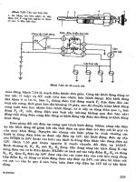
Testing at full scale has been done in a catalytic combustor system devel-
oped by GE for its MS9001E gas turbine. The MS9001E combustor operates
with a full load firing temperature of 2020
F (1105
C) and a combustor exit
temperature of about 2170
F (1190
C). The key components of the test
stand at the GE Power Generation Engineering Laboratories in Schenec-
tady, New York, are shown in Figure 10-28.
Surface
Gas
Inlet
Stage
Outlet
Stage
Homogeneous
Combustion
Temperature
Fuel
+
Air
Figure 10-27. Schematic temperature profiles for catalytica combustion system in
which the wall temperature is limited and complete combustion occurs after the
catalyst.
406 Gas Turbine Engineering Handbook
//INTEGRA/B&H/GTE/FINAL (26-10-01)/CHAPTER 10.3D ± 407 ± [370±408/39] 29.10.2001 4:02PM
There are four major subassemblies in the overall combustion system: the
preburner, the main fuel injector, the catalytic reactor.
Preburner. The preburner carries the machine load at operating points
where the conditions in the catalytic reactor are outside of the catalyst
operating window. Most often, these are the low load points where the
fuel required for turbine operation is insufficient for the catalyst to generate
the necessary minimum exit gas temperature. As the turbine load is
increased, progressively more fuel is directed through the main injector
and progressively less goes to the preburner. Ultimately, the preburner
receives only enough fuel to maintain the catalyst above its minimum inlet
temperature.
Main fuel injector. This unit is designed to deliver a fuel-air mixture to
the catalyst that is uniform in composition, temperature, and velocity.
A multi-venturi tube (MVT) fuel injection system was developed by GE
specifically for this purpose. It consists of 93 individual venturi tubes
arrayed across the flow path, with four fuel injection orifices at the throat
of each venturi.
Catalytic reactor. The role of the catalyst was described earlier; it
must burn enough of the incoming fuel to generate an outlet gas temperature
high enough to initiate rapid homogeneous combustion just past the catalyst
exit.
Figure 10-28. Schematic of a full scale catalytic combustor. Courtesy GE Power
Systems and Catalytica Combustion Systems Inc.
Combustors 407
//INTEGRA/B&H/GTE/FINAL (26-10-01)/CHAPTER 10.3D ± 408 ± [370±408/39] 29.10.2001 4:02PM
The catalytic combustor has great potential in the application of gas
turbines in new combined cycle power plants as the NO
x
emissions in high
attainment areas will have to be below 2 ppm.
Bibliography
Ballal, D.R., and Lefebvre, A.H., ``A Proposed Method for Calculating Film
Cooled Wall Temperatures in Gas Turbine Combustor Chambers,'' ASME
Paper #72-WA/HT-24, 1972.
Clarke, J.S., and Lardge, H.E., ``The Performance and Reliability of Aero-Gas
Turbine Combustion Chambers,'' ASME 58-GTO-13, 1958.
Dalla Betta, Ralph A., Nickolas, S.G., Weakley, C.K., Lundberg, K., Caron,
T.J., Chamberlain, J., and Greeb, K., ``Field Test of a 1.5 MW Industrial
Gas Turbine with a Low Emissions Catalytic Combustion System,'' ASME
99-GT-295.
Dutta, P., Cowell, L.H., Yee, D.K., and Dalla Betta, R.A., ``Design and Evalua-
tion of a Single-Can Full Scale Catalytic Combustion System for Ultra-Low
Emissions Industrial Gas Turbines,'' ASME 97-GT-292.
Faires, V.M., and Simmang, C.M., Thermodynamics, 6th ed., The Macmillan
Co., New York, 1978, pp. 345
Â
±347.
Grahman, J., Jones, R.E., Mayek, C.J., and Niedzwicki, R.W., Aircraft Propul-
sion, Chapter 4. NASA SP-259.
Greenwood, S.A., ``Low Emission Combustion Technology for Stationary Gas
Turbine Engines,'' Proceedings of the 29th Turbomachinery Symposium,
September 2000.
Hilt, M.B., and Johnson, R.H., ``Nitric Oxide Abatement in Heavy Duty Gas
Turbine Combustors by Means of Aerodynamics and Water Injection,''
ASME Paper #72-GT-22, 1972.
Maurice, L.Q.W., and Blust, J.W., ``Emission from Combustion of Hydrocar-
bons in a Well Stirred Reactor,'' AIAA 1999.
O'Brien, W.J., ``Temperature Measurement for Gas Turbine Engines,'' SAE
Paper #750207,1975.
Schlatter, J.C., Dalla Betta, R.A., Nickolas, S.G., Cutrone, M.B., Beebe, K.W.,
and Tsuchiya, T., ``Single-Digit Emissions in a Full Scale Catalytic Combus-
tor,'' ASME 97-GT-57.
Yee, D.K., Lundberg, K., and Weakley, C.K., ``Field Demonstration of a
1.5 MW Industrial Gas Turbine with a Low Emissions Catalytic Combustion
System,'' ASME 2000-GT-88.
408 Gas Turbine Engineering Handbook
G:/GTE/FINAL (26-10-01)/CHAPTER 11.3D ± 409 ± [409±435/27] 1.11.2001 3:50PM
Part III
Materials,
Fuel Technology,
and Fuel Systems