Ship Stability for Masters and Mates 5 Episode 4 pps
Bạn đang xem bản rút gọn của tài liệu. Xem và tải ngay bản đầy đủ của tài liệu tại đây (562.43 KB, 35 trang )
Chapter 11
Final KG
When a ship is completed by the builders, certain written stability
information must be handed over to the shipowner with the ship. Details
of the information required are contained in the load line Rules, parts of
which are reproduced in Appendix I of this book. The information includes
details of the ship's Lightweight, the Lightweight VCG and LCG, and also
the positions of the centres of gravity of cargo and bunker spaces. This
gives an initial condition from which the displacement and KG for any
condition of loading may be calculated. The ®nal KG is found by taking the
moments of the weights loaded or discharged, about the keel. For
convenience, when taking the moments, consider the ship to be on her
beam ends.
In Figure 11.1(a), KG represents the original height of the centre of
gravity above the keel, and W represents the original displacement. The
original moment about the keel is therefore W ÂKG.
Now load a weight w
1
with its centre of gravity at g
1
and discharge w
2
from g
2
. This will produce moments about the keel of w
1
ÂKg
1
and
(a)
(b)
Fig. 11.1
w
2
ÂKg
2
in d irections indicated in the ®gure. The ®nal moment about the
keel will be equal to the original moment plus the moment of the weight
added minus the moment of the weight discharged. But the ®nal moment
must also be equal to the ®nal displacement multiplied by the ®nal KG as
shown in Figure 11.1(b). i.e.
Final moment Final KG ÂFinal displacement
or
Final KG
Final moment
Final displacement
Example 1
A ship of 6000 tonnes displacement has KG 6 m and KM 7.33 m. The
following cargo is loaded:
1000 tonnesY KG 2X5m
500 tonnesY KG 3X5m
750 tonnesY KG 9X0m
The following is then discharged:
450 tonnes of cargo KG 0X6m
and 800 tonnes of cargo KG 3X0m
Find the ®nal GM.
Final KG 95
Weight KG Moment about
the keel
6000 6.0 36 000
1000 2.5 2500
500 3.5 1750
750 9.0 6750
8250 47 000
À450 0.6 À270
À800 3.0 À2400
7000 44 330
Final KG
Final moment
Final displacement
44 330
7000
6X33 m
GM KM À KG
KM 7X33 mY as given
Final KG
6X33 mY as calculated
Ans.
Final GM 1.00 m
Note. KM was assumed to be similar value at 6000 tonnes and 7000 tonnes
displacement. This is feasible. As can be seen on Figure 6.2, it is possible to
have the same KM at two different drafts.
Example 2
A ship of 5000 tonnes displacement has KG 4.5 m, KM 5.3 m. The following
cargo is loaded:
2000 tonnes KG 3X7mY and 1000 tonnes KG 7X5mX
Find how much deck cargo (KG 9 m) may now be loaded if the ship is to sail
with a minimum GM of 0.3 m.
Let `x' tonnes of deck cargo be loaded, so that the vessel sails with
GM 0.3 m.
Final KM 5X3m
Final GM 0X3m
Final KG 5X0m
Final KG
Final moment
Final displacement
5X0m
; 5
37 400 9x
8000 x
40 000 5x 37 400 9x
2600 4x
x 650 tonnes
Ans.
Maximum to load 650 tonnes
96 Ship Stability for Masters and Mates
Weight KG Moment about
the keel
5000 4.5 22 500
2000 3.7 7400
1000 7.5 7500
x 9.0 9x
8000 x 37 400 9x
Final KG 97
Exercise 11
1 A ship has a displacement of 1800 tonnes and KG 3 m. She loads 3400
tonnes of cargo (KG 2.5 m), and 400 tonnes of bunkers (KG 5.0 m).
Find the ®nal KG.
2 A ship has a light displacement of 2000 to nnes and light KG 3.7 m. She
then loads 2500 tonnes of carg o (KG 2.5 m), and 300 tonnes of bunkers
(KG 3 m). Find the new KG.
3 A ship sails with displacement 3420 tonnes and KG 3.75 m. During the
voyage bunkers were consumed as follows: 66 tonnes (KG 0.45 m) and
64 tonnes (KG 2 m). Find the KG at the end of the voyage.
4 A ship has displacement 2000 tonnes and KG 4 m. She loads 1500 tonnes
of cargo (KG 6 m), 3500 tonnes of cargo (KG 5 m), and 1520 tonnes of
bunkers (KG 1 m). She then discharges 2000 tonnes of cargo
(KG 2.5 m) and consumes 900 tonnes of oil fuel (KG 0.5 m) during
the voyage. Find the ®nal KG on arrival at the port of destination.
5 A ship has a light displacement of 2000 tonnes (KG 3.6 m). She loads
2500 tonnes of cargo (KG 5 m) and 300 tonnes of bunkers (KG 3 m).
The GM is then found to be 0.15 m. Find the GM with the bunkers empty.
6 A ship has a displacement of 3200 tonnes (KG 3 m, and KM 5.5 m) She
then loads 5200 tonnes of cargo (KG 5.2 m). Find how much deck cargo
having a KG 10 m may now be loaded if the ship is to complete loading
with a positive GM of 0.3 m.
7 A ship of 5500 tonnes displacement has KG 5 m, and she proceeds to load
the following cargo:
1000 tonnes KG 6 m
700 tonnes KG 4 m
300 tonnes KG 5 m
She then discha rges 200 tonnes of ballast KG 0.5 m. Find how much deck
cargo (KG 10 m) can be loaded so that the ship may sail with a positive
GM of 0.3 metres. The load KM is 6.3 m.
8 A ship of 3500 tonnes light displacement and light KG 6.4 m has to load
9600 tonnes of cargo. The KG of the lower hold is 4.5 m, and that of the
tween deck is 9 m. The load KM is 6.2 m and, when loading is completed,
the righting moment at 6 degrees of heel is required to be 425 tonnes m.
Calculate the amount of cargo to be loaded into the lower hold and tween
deck respectively (Righting moment W ÂGM Âsin heel.)
9 A ship arrives in port with displacement 6000 tonnes and KG 6 m. She then
discharges and loads the following quantities:
Discharge 1250 tonnes of cargo KG 4.5 metres
675 tonnes of cargo KG 3.5 metres
420 tonnes of cargo KG 9.0 metres
Load 980 tonnes of cargo KG 4.25 metres
550 tonnes of cargo KG 6.0 metres
98 Ship Stability for Masters and Mates
700 tonnes of bunkers KG 1.0 metre
70 tonnes of FW KG 12.0 metres
During the stay in port 30 tonnes of oil (KG 1 m) are consumed. If the ®nal
KM is 6.8 m, ®nd the GM on departure.
10 A ship has light displacement 2800 tonnes and light KM 6.7 m. She loads
400 tonnes of cargo (KG 6 m) and 700 tonnes (KG 4.5 m). The KG is then
found to be 5.3 m. Find the light GM.
11 A ship's displacement is 4500 tonnes and KG 5 m. The following cargo is
loaded:
450 tonnes KG 7.5 m
120 tonnes KG 6.0 m
650 tonnes KG 3.0 m.
Find the amount of cargo to load in a 'tween deck (KG 6 m) so that the ship
sails with a GM of 0.6 m. (The load KM is 5.6 m)
12 A ship of 7350 tonnes displacement has KG 5.8 m and GM 0.5 m. Find
how much deck cargo must be loaded (KG 9 m) if there is to be a
metacentric height of not less than 0.38 m when loading is completed.
13 A ship is partly loaded and has a displacement of 9000 tonnes, KG 6 m, and
KM 7.3 m. She is to make a 19-day passage consuming 26 tonnes of oil per
day (KG 0.5 m). Find how much deck cargo she may load (KG 10 m) if the
GM on arrival at the destination is to be not less than 0.3 m.
Chapter 12
Calculating KB, BM,
and metacentric
diagrams
THE method used to determine the ®nal position of the centre of gravity
was examined in the previous chapter. To ascertain the GM for any
condition of loading it is necessary also to calculate the KB and BM (i.e.
KM) for any draft.
To ®nd KB
The centre of buoyancy is the centre of gravity of the underwater volume.
For a box-shaped vessel on an even keel, the underwater volume is
rectangular in shape and the centre of buoyancy will be at the half-length,
on the centre line, and at half the draft as shown in Figure 12.1(a).
Therefore, for a box-shaped vessel on an even keel: KB
1
2
draft.
For a vessel which is in the form of a triangular prism as shown in Figure
12.1(b) the underwater section will also be in the form of a triangular prism.
The centroid of a triangle is at 2/3 of the median from the apex. Therefore
the centre of buoyancy will be at the half-length, on the centre line, but the
KB 2/3 draft.
For an ordinary ship the KB may be found fairly accurately by Simpson's
Rules as explained in Chapter 10. The approximate depth of the centre of
buoyancy of a ship below the waterline usually lies between 0.44 Âdraft
Fig. 12.1(a). Box-shaped vessel
and 0.49 Âdraft. A closer approximation of thus depth can be obtained by
using Morrish's Formula, which states:
Depth of centre of buoyancy below waterline
1
3
d
2
V
A
where
d Mean draft
V Volume of displacement
and
A Area of the water-plane
The derivation of this formula is as follows:
In Figure 12.2, let ABC be the curve of water-plane areas plotted against
drafts to the load waterline. Let DE V/A and draw EG parallel to the base
cutting the diagonal FD in H.
It must ®rst be shown that area DAHC is equal to area DABC.
Rectangle AH Rectangle HC
; Triangle AGH Triangle HEC
and
Area AHCD Area AGED
Area AGED V/A ÂA
V
but
Area DABC V
; Area DAHC Area DABC
100 Ship Stability for Masters and Mates
Fig. 12.1(b). Triangular-shaped vessel
Fig. 12.1(c). Ship-shaped vessel
The distance of the centroid of DABC below AD is the distance of the
centre of buoyancy below the load waterline. It is now assumed that the
centroid of the area DAHC is the same distance below the load waterline as
the centroid of area DABC.
To ®nd the distance of the centroid of area DAHC below AD.
Area AGH
Area AGED
1
2
AGEGH
AGEAD
1
2
GH
AD
1
2
GF
AF
1
2
AF ÀAG
AF
1
2
d ÀAG
d
; Area AGH
1
2
dÀV/A
d
 Area AGED
The centroid of AGED is
1
2
V
A
from AD.
Now let triangle AGH be shifted to HEC.
The centroid of AGED will move parallel to the shift of the centroid of
AGH and the vertical component of this shift (x) is given by:
Calculating KB, BM, and metacentric diagrams 101
Fig. 12.2
x
AGH Âd/3
AGED
1
2
d ÀV/A
d
Â
d
3
 AGED
AGED
1
2
d ÀV/A
d
Â
d
3
1
6
d ÀV/A
The new vertical distance of the centroid below AD will now be given by:
Distance below AD
1
2
V
A
1
6
d À
V
A
1
3
V
A
1
6
d
1
3
d
2
V
A
Therefore the distance of the centre of buoyancy below the load waterline
is given by the formula:
Distance below LWL
1
3
d
2
V
A
This is known as Morrish's or Normand's formula and will give very good
results for merchant ships.
To ®nd Transverse BM
The Transverse BM is the height of the transverse metacentre above the
centre of buoyancy and is found by using the formula:
BM
1
V
where
1 The second moment of the water-plane area about the centre line,
and
V The ship's volume of displacement
The derivation of this formula is as follows:
Consider a ship inclined to a small angle (y) as shown in Figure 12.3(a)
Let `y' be the half-breadth.
102 Ship Stability for Masters and Mates
Since y is a small angle then arc WW
1
arc LL
1
y y
Also:
Area of wedge WOW
1
Area of wedge LOL
1
1
2
y y
2
Consider an elementary wedge of longitudinal length dx as in Figure
12.3(b).
Calculating KB, BM, and metacentric diagrams 103
Fig. 12.3(a)
Fig. 12.3(b)
The volume of this wedge
1
2
y y
2
dx
The moment of the wedge about the centre line
1
2
y y
2
dx Â
2
3
y
1
3
y y
3
dx
The total moment of both wedges
about the centre line
2
3
y y
3
dx
The sum of the moments of all such wedges
L
O
2
3
y y
3
dx
y
L
O
2
3
y
3
dx
But
L
O
2
3
y
3
dx
The second moment
of the water-plane
area about the ship
H
s centre line
'
I
;The sum of the moments
of the wedges
I Â y
But the sum of
the moments
v  gg
1
where v is the volume of the immersed or emerg ed wedge.
; I Â y v Âgg
1
or
I
v Âgg
1
y
I
Now:
BB
1
v Âgg
1
V
and
BB
1
BM Â y
; BM Â y
v Âgg
1
V
or
BM ÂV
v Âgg
1
y
Substituting in (I) above:
BM ÂV I
; BM
I
V
104 Ship Stability for Masters and Mates
For a rectangular water-plane area the second moment about the centre line
is found by the formula:
I
LB
3
12
where L the length of the water-plane, and B = the breadth of the water-
plane, (the derivation of this formula is shown in Chapter 29).
Thus, for a vessel having a rectangular water-plane area:
BM
LB
3
12V
For a box-shaped vessel:
BM
1
V
LB
3
12V
L ÂB
3
12 ÂL ÂB Âdraft
; BM
B
2
12d
where B the beam of the vessel, and d any draft of the vessel. B is a
constant, d is a variable.
For a triangular-shaped prism:
BM
I
V
LB
3
12V
L ÂB
3
12
1
2
 L  B  draft
; BM
B
2
6d
where B is the breadth at the waterline and d is the corresponding draft. B
and d are variables.
Example 1
A box-shaped vessel is 24 m Â5mÂ5 m and ¯oats on an even keel at 2 m
draft. KG 1.5 m. Calculate the initial metacentric height.
Calculating KB, BM, and metacentric diagrams 105
KB
1
2
draft BM
B
2
12d
KB 1X00 m
BM 1X04 m
KB 1m BM
5
2
12 Â 2
KM 2X04 m
KG À1X50 m
BM 1X04 m GM 0X54 m
Ans.
GM 0X54 m
Example 2
A vess el is in the form of a triangular prism 32 m long, 8 m wide at the top, and
5 m deep. KG 3.7 m. Find the initial metacentric height when ¯oating on
even keel at 4 m draft F and A.
Let `x' be the half-breadth at the waterline, as shown in Figure 12.4.
Then
x
4
4
5
x
16
5
x 3X2m
; The breadth at the waterline 6X4m
KB 2a3 draft BM
B
2
6d
KB 2X67 m
2a3 Â 4BM1X71 m
KB 2X67 m
6X4 Â 6X4
6 Â 4
KM 4X38 m
KG À3X70 m
BM 1X71 m GM 0X68 m
Ans.
GM 0X68 m
Note how the breadth `B' would decrease at the lower drafts. See also Figure
12.6(b).
106 Ship Stability for Masters and Mates
Fig. 12.4
Example 3
The second moment of a ship's water-plane area about the centre line is
20 000 m
4
units. The displacement is 7000 tonnes whilst ¯oating in dock water
of density 1008 kg per cu. m. KB 1.9 m, and KG 3.2 m. Calculate the initial
metacentric height.
Volume of water displaced
7000 Â 1000
1008
cu. m 6944 cu. m
BM
I
V
; BM
20 000
6944
BM 2X88 m
KB 1X90 m
KM 4X78 m
KG 3X20 m
Ans.
GM 1X58 m
Metacentric diagrams
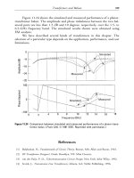
It has been mentioned in Chapter 6 that the of®cer responsible for loading a
ship should aim to complete the loading with a GM which is neither too large
nor too small. See table of typical GM values on p. 49 for merchant ships when
fully loaded. A metacentric diagram is a ®gure in graph form from which the
KB, BM, and thus the KM can be found for any draft by inspection. If the KG is
known and the KM is found from the diagram, the difference will give the
GM. Also, if a ®nal GM be decided upon, the KM can be taken from the graph
and the difference will give the required ®nal KG.
The diagram is usually drawn for drafts between the light and loaded
displacements, i.e. 3 m and 13 m respectively overpage.
Figure 12.5 shows a metacentric diagram drawn for a ship having the
following particulars:
Draft (m) KB (m) KM (m)
13 6.65 11.60
12 6.13 11.30
11 5.62 11.14
10 5.11 11.10
9 4.60 11.15
8 4.10 11.48
7 3.59 11.94
6 3.08 12.81
5 2.57 14.30
4 2.06 16.63
3 1.55 20.54
±± ±
Calculating KB, BM, and metacentric diagrams 107
108 Ship Stability for Masters and Mates
Fig. 12.5. Metacentric diagram for a ship-shaped vessel.
The following is a description of the method used in constructing this
diagram. The scale on the left-hand side represents a scale of metres, and it
is from this scale that all measurements are to be taken.
First the curve of the Centres of Buoyancy is plotted.
For each draft plot the corresponding KB. For example, plot 6.65 m @
13 m, 6.13 m @ 12 m draft and so on to 1.55 m @ 3 m draft.
Join these points together to form the KB curve. In practice it will be very
close to being a straight line because the curvature will be so small. See
Figure 12.5.
Next the KM curve or Locus of Metacentres. For each draft plot the
corresponding KM value given in the table.
At 13 m plot 11.60 m. At 12 m plot 11.30 m and so on down to plotting
20.54 m KM @ 3 m draft.
These points are then joined by a smooth curve as shown in Figure 12.5.
Note how it is possible for two different drafts to have the same value of
KM in the range of drafts from 7 m to 13 m approximately.
For any draft being considered, the vertical distance between the KB line
and the KM curve gives the BM value.
To ®nd the KB's and KM's the vertical distances are measured from the
base line to the curves.
Example 1
Construct the metacentric diagram for a box-shaped vessel 64 m long, 10 m
beam, and 6 m deep, for even keel drafts at 0.5 m intervals between the light
draft 1 metre and the load draft 5 m. Also, from the diagram ®nd:
(a) The minimum KM and the draft at which it occurs, and
(b) The BM at 3.5 m.
Draft KB
1
2
draft BM B
2
/12d KM KB BM
1 m 0.5 m 8.33 m 8.83 m
1.5 m 0.75 m 5.56 m 6.31 m
2 m 1.0 m 4.17 m 5.17 m
2.5 m 1.25 m 3.33 m 4.58 m
3.0 m 1.5 m 2.78 m 4.28 m
3.5 m 1.75 m 2.38 m 4.13 m
4.0 m 2.00 m 2.08 m 4.08 m
4.5 m 2.25 m 1.85 m 4.10 m
5.0 m 2.5 m 1.67 m 4.17 m
See Figure 12.6(a) for KB and KM plotted against draft.
Explanation. To ®nd the minimum KM, draw a horizontal tangent to the lowest
point of the curve of metacentres, i.e. through A. The point where the tangent
cuts the scale will give the minimum KM and the draft at which it occurs.
Note. It is shown below that for a box-shaped vessel the minimum KM and the
draft at which it occurs are both given by B/
6
p
, where B is the beam.
Calculating KB, BM, and metacentric diagrams 109
110 Ship Stability for Masters and Mates
Fig. 12.6(a). Metacentric diagram for a box-shaped vessel.
Therefore, the answer to part (a) of the question is:
Minimum KM 4.08 m occurring at 4.08 m draft
To ®nd the BM at 3.5 m draft, measure the distance DE on the scale and it
will give the BM (2.38 m).
Therefore, the answer to part (b) of the question is:
BM at 3.5 m draft 2X38 m
To show that, for a box-shaped vessel, the minimum KM and the draft at which
it occurs are both given by the expression B/
6
p
, where B is equal to the
vessel's beam.
KM KB BM
For a box-shaped vessel:
KM
d
2
B
2
12d
I
dKM
dd
1
2
B
2
12d
2
For minimum KM:
dKM
dd
O
; O
1
2
B
2
12d
2
B
2
6d
2
and
d Ba
6
p
Substituting in equation (I) above:
minimum KM
B
2
6
p
B
2
6
p
12B
6B 6B
12
6
p
minimum KM Ba
6
p
Figure 12.6(b) shows a metacentric diagram for a triangular-shaped underwater
form with apex at the base. Note how the KM values have produced a straight
line instead of the parabolic curve of the rectangular hull form. Note also how
BM increases with every increase in draft.
Calculating KB, BM, and metacentric diagrams 111
112 Ship Stability for Masters and Mates
Fig. 12.6(b). Metacentric diagram for triangular-shaped vessel.
Calculating KB, BM, and metacentric diagrams 113
Exercise 12
1 A box-shaped vessel 75 m long, 12 m beam and 7 m deep, is ¯oating on an
even keel at 6 m draft. Calculate the KM.
2 Compare the initial metacentric heights of two barges, each 60 m. long,
10 m beam at the waterline, 6 m deep, ¯oating upright on an even keel at
3 m draft, and having KG 3 m. One barge is in the form of a rectangular
prism and the other is in the form of a triangular prism, ¯oating apex
downwards.
3 Two box-shaped vessels are each 100 m long, 4 m deep , ¯oat at 3 m draft,
and have KG 2.5 m. Compare their initial Metacentric Heights if one has
10 m beam and the other has 12 m beam.
4 Will a homogeneous log of square cross-section and relative density 0.7
have a positive initial Metacentric Height when ¯oating in fresh water with
one side parallel to the waterline? Verify your answer by means of a
calculation.
5 A box-shaped vessel 60 m Â12 m Â5 m is ¯oating on an even keel at a
draft of 4 m. Construct a metacentric diagram for drafts between 1 m and
4 m. From the diagram ®nd:
(a) the KM's at drafts of 2.4 m and 0.9 m, and
(b) the draft at which the minimum KM occurs.
6 Construct a metacentric diagram for a box-shaped vessel
65 m Â12 m Â6 m for drafts between 1 m and 6 m. From the diagram ®nd:
(a) the KM's at drafts of 1.2 m and 3.6 m, and
(b) the minimum KM and the draft at which it occurs.
7 Construct a metacentric diagram for a box-shaped vessel 70 m long and
10 m beam, for drafts between 1 m and 6 m. From the diagram ®nd:
(a) the KM's at drafts of 1.5 m and 4.5 m, and
(b) the draft at which the minimum KM occurs.
8 A box-shaped vessel is 60 m long, 13.73 m wide and ¯oats at 8 m even-keel
draft in salt water.
(a) Calculate the KB, BM and KM values for drafts 3 m to 8 m at intervals
of 1 m. From your results draw the Metacentric Diagram.
(b) At 3.65 m draft even keel, it is known that the VCG is 4.35 m above
base. Using your diagram, estimate the transve rse GM for this
condition of loading.
(c) At 5.60 m draft even keel, the VCG is also 5.60 m above base. Using
your diagram, estimate the GM for this condition of loading. What
state of equilibrium is the ship in?
Draft (m) 3 4 5 6 7 8
KM (m) 6.75 5.94 5.64 5.62 5.75 5.96
Chapter 13
List
Consider a ship ¯oating upright as shown in Figure 13.1. The centres of
gravity and buoyancy are on the centre line. The resultant force acting on
the ship is zero, and the resultant moment about the centre of gravity is
zero.
Now let a weight already on board the ship be shifted transversely such
that G moves to G
1
as in Figure 13.2(a). This will produce a listing moment
of W ÂGG
1
and the ship will list until G
1
and the centre of buoyancy are
in the same vertical line as in Figure 13.2(b).
In this position G
1
will also lie vertically under M so long as the angle of
list is small. Therefore, if the ®nal positions of the metacentre and the centre
of gravity are known, the ®nal list can be found, using trigonometry, in the
triangle GG
1
M which is right-angled at G.
The ®nal position of the centre of gravity is found by taking moments
about the keel and about the centre line.
Note. It will be found more convenient in calculations, when taking
moments, to consider the ship to be upright throughout the operation.
Fig. 13.1
Example 1
A ship of 6000 tonnes displacement has KM 7.3 m, and KG 6.7 m, and is
¯oating upright. A weight of 60 tonnes already on board is shifted 12 m
transversely. Find the resultant list.
Figure 13.3(a) shows the initial position of G before the weight was shifted
and Figure 13.3(b) shows the ®nal position of G after the weight has been
shifted.
When the weight is shifted transversely the ship's centre of gravity will also
shift transversely, from G to G
1
. The ship will then list y degrees to bring G
1
vertically under M the metacentre.
GG
1
w  d
W
60 Â 12
6000
GG
1
0X12 m
GM KM À KG 7X3 À 6X7 0X6m
In triangle GG
1
M:
tan y
GG
1
GM
0X12
0X60
0X20
Ans.
List 11
18
1
2
H
Example 2
A ship of 8000 tonnes displacement has KM 8.7 m, and KG 7.6 m. The
following weights are then loaded and discharged:
Load 250 tonnes cargo KG 6.1 m and centre of gravity 7.6 m to starboard of
the centre line.
List 115
Fig. 13.2
Load 300 tonnes fuel oil KG 0.6 m and centre of gravity 6.1 m to port of the
centre line.
Discharge 50 tonnes of ballast KG 1.2 m and centre of gravity 4.6 m to port
of the centre line.
Find the ®nal list.
Note. In this type of problem ®nd the ®nal KG by taking moments about the
keel, and the ®nal distance of the centre of gravity from the centre line by
taking moments about the centre line.
Moments about the keel
Final KG
Final moment
Final displacement
62 445
8500
Final KG 7X35 m
KM 8X70 m
Final KG À7X35 m
Final GM 1X35 m
116 Ship Stability for Masters and Mates
Fig. 13.3
Weight KG Moments about keel
8000 7.6 60 800
250 6.1 1 525
300 0.6 180
8550 62 505
À50 1.2 À60
8500 62 445
Moments about the centre line (as in Figure 13.4(a))
For levers to port, use ve sign.
For levers to starboard, use Àve sign.
Let the ®nal position of the centre of gravity be as shown in Figure 13.4(b)
; Final listing moment W Â GG
1
or
GG
1
Final moment
Final displacement
À300
8500
À0X035 m
GG
1
0X035 m to starboard, because of the À ve sign used in tableX
Since the ®nal position of the centre of gravity must lie vertically under M, it
follows that the ship will list y degrees to starboard.
List 117
Fig. 13.4
w d Listing moment
to port to starboard
ve À ve
250 À7X6±À1900
À50 4X6±À230
300 6X1 1830 ±
1830 À2130
1830
®nal moment À300
tan y
GG
1
GM
À0X035
1X35
À0X0259
;y 1
29
H
Ans. Final list 1
29
H
to starboard
Example 3
A ship of 8000 tonnes displacement has a GM 0.5 m. A quantity of grain in
the hold, estimated at 80 tonnes, shifts and, as a result, the centre of gravity of
this grain moves 6.1 m horizontally and 1.5 m vertically. Find the resultant list.
Referring to Figure 13.5, let the centre of gravity of the grain shift from g to g
2
.
This will cause the ship's centre of gravity to shift from G to G
2
in a direction
parallel to gg
2
. The horizontal components of these shifts are g to g
1
andGto
G
1
respectively, whilst the vertical components are g
1
g
2
and G
1
G
2
.
GG
1
w  d
W
80 Â 6X1
8000
GG
1
0X061 m
G
1
G
2
w  d
W
80 Â 1X5
8000
G
1
G
2
0X015 m
In Figure 13.5
GX G
1
G
2
GX 0X015 m
GM 0X500 m
XM 0X485 m
XG
2
GG
1
XG
2
0X061 m
tan y
XG
2
MX
tan y
0X061
0X485
0X126
tan y 0X126
Ans.
List 7
12
H
118 Ship Stability for Masters and Mates
Fig. 13.5
![ship stability for masters and mates [electronic resource]](https://media.store123doc.com/images/document/14/y/bj/medium_bjc1401370968.jpg)