Ship Stability for Masters and Mates 5 Episode 7 ppt
Bạn đang xem bản rút gọn của tài liệu. Xem và tải ngay bản đầy đủ của tài liệu tại đây (541.47 KB, 35 trang )
The following worked example shows the effect of subdivisions in slack
tanks in relation to free surface effects (FSE):
Question: A ship has a displacement of 3000 tonnes. On the vessel is a
rectangular double-bottom tank 15 m long and 8 m wide. This tank is
partially ®lled with ballast water having a density of 1.025 t/m
3
.
If the GM
T
without free surface effects is 0.18 m calculate the virtual loss
in GM
T
and the ®nal GM
T
when the double bottom tank has:
(a) no divisional bulkheads ®tted;
(b) one transverse bulkhead ®tted at mid-length;
(c) one longitudinal bulkhead ®tted on
c
L of the tank;
(d) two longitudinal bulkheads ®tted giving three equal divisions.
Answer
FSEvirtual loss in GM
T
or rise in G
I Â r
SW
W
l  b
3
1
 r
SW
12 Â W
see FigX 20X4a
;
virtual loss in GM
T
15 Â 8
3
 1X025
3000 Â 12
0X02187 m 4
; GM
T
finally 0X1800 À0X2187
À
0X0387 m 4
i.e. unstable ship!!
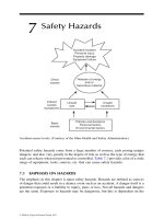
Calculating the effect of free surface of liquids (FSE) 199
Fig. 20.4(a)
FSEvirtual loss in GM
T
or rise in G
2 @ l
2
 b
3
1
12 Â W
 r
SW
(see Fig. 20.4(b))
; virtual loss
2 Â 7X5 Â8
3
 1X025
12 Â 3000
0X2187 m 4
This is same answer as for part (a). Consequently it can be concluded that
®tting transverse divisional bulkheads in tanks does not reduce the free
surface effects. Ship is still unstable!!
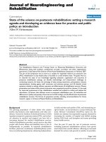
FSEvertical loss in GM
T
or rise in G
2 @ l
1
b
3
2
12 Â W
r
SW
; virtual loss in GM
T
2Â15Â4
3
Â1X025
12 Â 3000
see FigX 20X4c
0X0547 m 4 iXeX
1
4
of answer to part a
Hence
final GM
T
0X1800 À 0X0547 m 0X1253 m Ship is stable.
200 Ship Stability for Masters and Mates
Fig. 20.4(b)
Fig. 20.4(c)
GM
T
is now ve, but below the minimum GM
T
of 0.15 m that is
allowable by D.Tp. regulations.
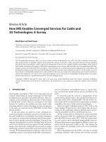
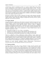
FSEvirtual loss in GM
T
or rise in G
3 d l
1
 b
3
3
12 Â W
 r
SW
(see Fig. 20.4(d))
; Virtual loss in GM
T
3 Â 15 Â
8
3
3
Â1X025
12 Â W
0X0243 m 4 i.e.
1
9
of answer to part (a)
Hence
final GM
T
0 X1800 À 0X0243 0X1557 m ship is stable.
Ship is stable and above D.Tp. minimum GM
T
value of 0.15 m.
So longitudinal divisional bulkheads (watertight or wash-bulkheads) are
effective. They cut down rapidly the loss in GM
T
. Note the 1/n
2
law where
n is the number of equal divisions made by the longitudinal bulkheads.
Free surface effects therefore depend on:
(I) density of slack liquid in the tank;
(II) ship's displacement in tonnes;
(III) dimensions and shape of the slack tanks;
(IV) bulkhead subdivision within the slack tanks.
The longitudinal divisional bulkheads referre d to in examples in this chapter
need not be absolutely watertight; they could have openings in them.
Examples on board ship are the centreline wash bulkhead in the Fore Peak
tank and in Aft Peak tank.
Calculating the effect of free surface of liquids (FSE) 201
Fig. 20.4(d)
202 Ship Stability for Masters and Mates
Exercise 20
1 A ship of 10 000 tonnes displacement is ¯oating in dock water of density
1024 kg per cu. m, and is carrying oil of relative density 0.84 in a double-
bottom tank. The tank is 25 m long, 15 m wide, and is divided at the centre
line. Find the virtual loss of GM due to this tank being slack.
2 A ship of 6000 tonnes displacement is ¯oating in fresh water and has a
deep tank (10 m Â15 m Â6 m) which is undivided and is partly ®lled with
nut oil of relative density 0.92. Find the virtual loss of GM due to the free
surface.
3 A ship of 8000 tonnes displacement has KG 3.75 m, and KM 5.5 m. A
double-bottom tank 16 mÂ16m Â1 m is subdivided at the centre line and
is full of salt water ballast. Find the new GM if this tank is pumped out until
it is half empty.
4 A ship of 10 000 tonnes displacement, KM 6 m, KG 5.5 m, is ¯oating
upright in dock water of density 1024 kg per cu. m. She has a double
bottom tank 20 m Â15 m which is subdivided at the centre line and is
partially ®lled with oil of relative density 0.96. Find the list if a mass of 30
tonnes is now shifted 15 m transversely across the deck.
5 A ship is at the light displacement of 3000 tonnes and has KG 5.5 m, and
KM 7.0 m. The following weights are then loaded:
5000 tonnes of cargo KG 5 m
2000 tonnes of cargo KG 10 m
700 tonnes of fuel oil of relative density 0.96.
The fuel oil is taken into Nos. 2, 3 and 5 double bottom tanks, ®lling
Nos. 3 and 5, and leaving No. 2 slack.
The ship then sails on a 20-day passage consuming 30 tonnes of fuel
oil per day. On arrival at her destination Nos. 2 and 3 tanks are empty,
and the remaining fuel oil is in No. 5 tank. Find the ship's GM's for the
departure and arrival conditions.
Dimensions of the tanks:
No. 2 15Â15 m Â1m
No. 3 22 m  15 m Â1m
No. 5 12 m  15 m Â1m
Assume that the KM is constant and that the KG of the fuel oil in every
case is half of the depth of the tank.
6 A shi p's displacement is 5100 tonnes, KG 4 m, and KM 4.8 m. A
double-bottom tank on the starboard side is 20 m long, 6 m wide and 1 m
deep and is full of fresh water. Calculate the list after 60 to nnes of this
water has been consumed.
7 A ship of 6000 tonnes displacement has KG 4 m and KM 4.5 m. A double-
bottom tank in the ship 20 m long and 10 m wide is partly full of salt-water
Calculating the effect of free surface of liquids (FSE) 203
ballast. Find the moment of statical stability when the ship is heeled 5
degrees.
8 A box-shaped vessel has the following data.
Length is 80 m, breadth is 12 m, draft even keel is 6 m, KG is 4.62 m.
A double bottom tank 10 m long, of full width and 2.4 m depth is then
half-®lled with water ballast having a density of 1.025 t/m
3
. The tank is
located at amidships.
Calculate the new even keel draft and the new transverse GM after
this water ballast has been put in the double bottom tank.
Chapter 21
Bilging and
permeability
Bilging amidships compartments
When a vessel ¯oats in still water it displaces its own weight of water.
Figure 21.1(a) shows a box-shaped vessel ¯oating at the waterline WL. The
weight of the vessel (W) is considered to act downwards through G, the
centre of gravity. The force of buoyancy is also equal to W and acts
upwards through B, the centre of buoyancy. b W.
Now let an empty compartment amidships be holed below the waterline
to such an extent that the water may ¯ow freely into and out of the
compartment. A vessel holed in this way is said to be `bilged'.
Figure 21.1(b) shows the vessel in the bilged condition. The buoyancy
provided by the bilged compartment is lost. The draft has increased and the
vessel now ¯oats at the waterline W
1
L
1
, where it is again displacing its own
Fig. 21.1(a)
weight of water. `X' represents the increase in draft due to bilging. The
volume of lost buoyancy (v) is made good by the volumes `y' and `z'.
; v y z
Let `A' be the area of the water-plane before bilging, and let `a' be the
area of the bilged compartment. Then:
y z Ax Àax
or
v xA Àa
Increase in draft x
v
A À a
i.e.
Increase in draft
Volume of lost buoyancy
Area of intact waterplane
Note. Since the distribution of weight within the vessel has not been altered
the KG after bilging will be the same as the KG before bilging.
Example 1
A box-shaped vessel is 50 metres long and is ¯oating on an even keel at 4
metres draft. A compartment amidships is 10 metres long and is empty. Find
the increase in draft if this compartment is bilged. See Fig. 21.1(c).
x
v
A À a
l  B  B
L À lB
let
B Breadth of the vessel
then
x
10 Â B Â 4
50 Â B À 10 ÂB
40B
40B
Increase in draft 1 metre
Bilging and permeability 205
Fig. 21.1(b)
Example 2
A box-shaped vessel is 150 metres long Â24 metres wide Â12 metres deep
and is ¯oating on an even keel at 5 metres draft. GM 0.9 metres. A
compartment amidships is 20 metres long and is empty. Find the new GM if
this compartment is bilged.
Old KB
1
2
Old draft
2X5m
Old BM B
2
a12d
24 Â 24
12 Â 5
9X6m
Old KB 2X5m
Old KM 12X1m
Old GM À0X9m
KG 11X2m
This KG will not change after bilging has taken place.
x
v
A À a
20 Â 24 Â 5
150 Â 24 À 20 Â24
2400
130 Â 24
Increase in draft 0X77 m
Old draft 5X00 m
New draft 5X77 m say draft d
2
206 Ship Stability for Masters and Mates
Fig. 21.1(c)
New KB
1
2
New draft
d
2
2
2X89 m
New BM B
2
a12d
2
24 Â 24
12 Â 5X77
8X32 m
New KB 2X89 m
New KM 11X21 m
À
As before, KG 11X20 m
Ans.
New GM 0X01 m
This is ve but dangerously low in value!!
Permeability k
Permeability is the amount of water that can enter a compartment or tank
after it has been bilged. When an empty compartment is bilged, the whole
of the bouyancy provided by that compartment is lost. Typical values for
permeability m are as follows:
Empty compartment m 100%
Engine room m 80% to 85%
Grain ®lled cargo hold m 60% to 65%
Coal ®lled compartment m 36% approx
Filled water ballast tank (when ship is in salt water) m 0%
Consequently, the higher the value of the permeability for a bilged
compartment, the greater will be a ship's loss of bouyancy when the ship is
bilged.
The permeability of a compartment can be found from the formula:
m Permeability
Broken Stowage
Stowage Factor
 100 per cent
The broken stowage to be used in this formula is the broken stowage per
tonne of stow.
When a bilged compartment contains cargo, the formula for ®nding the
increase in draft must be amended to allow for the permeability. If `m'
represents the permeability, expressed as a fraction, then the volume of lost
buoyancy will be `mn' and the area of the intact waterplane will be `A À mn'
square metres. The formula then reads:
x
mn
A À ma
Example 3
A box-shaped vessel is 64 metres long and is ¯oating on an even keel at 3
Bilging and permeability 207
metres draft. A compartment amidships is 12 m long and contains cargo having
a permeability of 25 per cent. Calculate the increase in the draft if this
compartment be bilged.
x
mn
A À ma
1
4
 12 ÂB  3
64 Â B À
1
4
 12 ÂB
9B
61B
Ans.
Increase in draft 0X15 m
Example 4
A box-shaped vessel 150 m  20 m  12 m is ¯oating on an even keel at 5
metres draft. A compartment amidships is 15 metres long and contains timber
of relative density 0.8, and stowage factor 1.5 cubic metres per tonne. Calculate
the new draft if this compartment is now bilged.
The permeability `m' must ®rst be found by using the formula given above.
i.e.
Permeability
BS
SF
 100 per cent ` m'
The stowage factor is given in the question. The broken stowage per tonne
of stow is now found by subtracting the space which would be occupied by
one tonne of solid timber from that actually occupied by one tonne of timber in
the hold. One tonne of fre sh water occupies one cubic metre and the relative
density of the timber is 0.8.
; Space occupied by one tonne of solid timber
1
0X8
1X25 cubic metres
Stowage Factor 1X50 cubic metres
; Broken Stowage 0X25 cubic metres
Permeability `m'
BS
SF
 100 per cent
0X25
1X50
 100 per cent
100a6 per cent
; `m' 1a6 or 16.67 per cent
Increase in draft x
mn
A À ma
1a6 Â 15 Â 20 Â5
150 Â 20 À 1a6 Â15 Â 20
250a2950 0X085 m
208 Ship Stability for Masters and Mates
Increase in draft 0X085 metres
Old draft
5X000 metres draft d
1
Ans. New draft 5X085 metres draft d
2
When the bilged compartment does not extend above the waterline, the area
of the intact waterplane remains constant as shown in Figure 21.2.
In this ®gure:
mn Ax
Let
d Density of the water, then
mn  d Ax Âd
but
mn  d Mass of water entering the bilged compartm ent, and
Ax  d Mass of the extra layer of water displaced.
Therefore, when the compartment is bilged, the extra mass of water displaced is
equal to the buoyancy lost in the bilged compartment. It should be carefully
noted, however, that although the effect on draft is similar to that of loading a
mass in the bilged compartment equal to the lost buoyancy, no mass has in fact
been loaded. The displacement after bilging is the same as the displacement
before bilging and there is no alteration in the position of the vessel's centre of
gravity. The increase in the draft is due solely to lost buoyancy.
Example 5
A ship is ¯oating in salt water on an even keel at 6 metres draft. TPC is 20
tonnes. A rectangular-shaped compartment amidships is 20 metres long, 10
metres wide, and 4 metres deep. The compartment contains cargo with
permeability 25 per cent. Find the new draft if this compartment is bilged.
Buoyancy lost
25
100
 20 Â10  4 Â1X025 tonnes
205 tonnes
Extra mass of water displaced TPC ÂX tonnes
Bilging and permeability 209
Fig. 21.2
; X w/TPC
205a20
Increase in draft 10X25 cm
0X1025 m
plus the old draft
6X0000 m
Ans.
New draft 6X1025 m
Note: The lower the permeability is the less will be the changes in end drafts
after bilging has taken place.
Bilging end compartments
When the bilged compartment is situated in a position away from
amidships, the vessel's mean draft will increase to make good the lost
buoyancy but the trim will also change.
Consider the box-shaped vessel shown in Figure 21.3(a). The vessel is
¯oating upright on an even keel, WL representing the waterline. The centre
of buoyancy (B) is at the centre of the displaced water and the vessel's
centre of gravity (G) is vertically above B. There is no trimming moment.
Now let the forward compartm ent which is X metres long be bilged. To
make good the loss in buoyancy, the vessel's mean draft will increase as
shown in Figure 21.3(b), where W
1
L
1
represents the new waterline. Since
there has been no change in the distribution of mass within the vessel, the
centre of gravity will remain at G. It has already been shown that the effect
on mean draft will be similar to that of loading a mass in the compartment
equal to the mass of water entering the bilged space to the original
waterline.
210 Ship Stability for Masters and Mates
Fig. 21.3
The vertical component of the shift of the centre of buoyancy (B to B
1
)is
due to the increase in the mean draft. KB
1
is equal to half of the new draft.
The horizontal component of the shift of the centre of buoyancy (B
1
B
2
)is
equal to X/2.
A trimming moment of W ÂB
1
B
2
by the head is produced and the vessel
will trim about the centre of ¯otation (F), which is the centre of gravity of
the new water-plane area.
B
1
B
2
w  d
W
or
W Â B
1
B
2
w  d
but
W Â B
1
B
2
Trimming moment,
; w  d Trimming moment
It can therefore be seen that the effect on trim is similar to that which
would be produced if a mass equal to the lost buoyancy were loaded in the
bilged compartment.
Note. When calculating the TPC, MCTC, etc., it mu st be remembered that
the information is required for the vessel in the bilged condition, using draft
d
2
and intact length l
2
.
Example 6
A box-shaped vessel 75 metres long Â10 metres wide Â6 metres deep is
¯oating in salt water on an even keel at a draft of 4.5 metres. Find the new
drafts if a forward compartment 5 metres long is bilged.
(a) First let the vessel sink bodily.
w x  B  d
1
 1X025 tonnes
5 Â10 Â 4X5 Â 1X025
w 230X63 tonnes
TPC
WPA
97X56
L
2
 B
97X56
70 Â 10
97X56
TPC 7X175
Bilging and permeability 211
Fig. 21.4
Increase in draft w/TPC
230.63/7.175
32X14 cm
0X321 m
Old draft 4X500 m draft d
1
New mean draft 4X821 m draft d
2
(b) Now consider the trim .
W L Â B Â d
1
 1X025 tonnes
75 Â10 Â 4X5 Â 1X025
W 3459 tonnes
BM
L
I
L
aV
BL
3
2
12V
10 Â 70
3
12 Â 75 Â 10 Â4X5
BM
L
84X7 metres
MCTC 9
W Â BM
L
100L
3459 Â 84X7
100 Â 75
39 X05 tonnes m per cm
Change of trim
Moment changing trim
MCTC
where
d
LBP
2
75
2
37 X5m lever from new LCF
230X6 Â 37X5
39X05
221X4 cm by the head
After bilging, LCF has moved to F, i.e. (L Àx)/2 from the stern
Change of draft aft
l
L
 Change of trim
35
75
 221X4
103X3cm 1X033 m
Change of draft forward
40
75
 221X4
118X1cm 1X181 m
212 Ship Stability for Masters and Mates
(c) Now ®nd new drafts.
Drafts before trimming A 4.821 m F 4.821 m
Change due to trim À1X033 m 1X181 m
Ans.
New Drafts A 3.788 m F 6.002 m
Example 7
A box-shaped vessel 100 metres long Â20 metres wide Â12 metres deep is
¯oating in salt water on an even keel at 6 metres draft. A forward compartment
is 10 metres long, 12 metres wide and extends from the outer bottom to a
watertight ¯at, 4 metres above the keel. The compartment contains cargo of
permeability 25 per cent. Find the new drafts if this compartment is bilged.
Mass of water entering
25
100
 10 Â12  4 Â1X025
the bilged compartment
123 tonnes
TPC
SW
WPA
97X56
100 Â 20
97X56
TPC 20X5 tonnes
Increase in draft w/TPC
123/20.5
6cm
Increase in draft 0X06 m
W L Â B Â d
1
 1X025
100 Â20 Â 6 Â1X025
W
12 300 tonnes
BM
L
I
L
V
BL
3
12V
B Â L
3
12 Â LÂBÂd
L
2
12 Â d
1
BM
L
100 Â 100
12 Â 6
BM
L
139 metres
MCTC 9
W Â BM
L
100 Â L
12 300 Â139
100 Â 100
Bilging and permeability 213
Fig. 21.5
MCTC 171 tonnes m per cm
Trimming moment W Â B
1
B
2
w Âd
Trimming moment 123 Â 45 tonnes m
Change of trim
Trimming moment
MCTC
123 Â 45
171
Change of trim 32X4 cm by the head,
i.e. 0.32 m by the head
Note. The centre of ¯otation, being the centroid of the water-plane area,
remains amidships.
Old drafts A 6.00 m F 6.00 m
Bodily increase 0X06 m 0X06 m
6X06 m 6X06 m
Change due to trim À0X16 m 0X16 m
Ans.
New Drafts A 5.90 m F 6.22 m
Effect of bilging on stability
It has already been shown that when a compartment in a ship is bilged the
mean draft is increased. The change in mean draft causes a change in the
positions of the centre of buoyancy and the initial metacentre. Hence KM is
changed and, since KG is constant, the GM will be changed.
Example 8
A box-shaped vessel 40 metres long, 8 metres wide and 6 metres deep, ¯oats in
salt water on an even keel at 3 metres draft. GM 1 metre. Find the new GM
if an empty compartment 4 metres long and situated amidships is bilged.
(a) Original condition before bilging.
Find the KG
KB
d
1
2
1X5 metres
BM
I
V
LB
3
12V
B
2
12 Â d
1
8 Â 8
12 Â 3
BM 1X78 m
KB 1X50 m
KM 3X28 m
GM À1X00 m
KG 2X28 m
214 Ship Stability for Masters and Mates
(b) Vessel's condition after bilging.
Find the New Draft
Lost buoyancy 4 Â 8 Â3 Â 1X025 tonnes
TPC
SW
WPA
97X56
36 Â 8
97X56
Increase in draft
Lost buoyancy
TPC
4 Â8 Â 3 Â 1X025 Â
100
36 Â 8 Â1X025
cm
33 X3 cm or 0.33 m
It should be noted that the increase in draft can also be found as follows:
Increase in draft
Volume of lost buoyancy
Area of intact water-plane
4 Â 8 Â 3
36 Â 8
1a3 metres.
Original draft 3X000 m draft d
1
New draft 3X333 m draft d
2
(c) Find the New GM
KB
d
2
2
1X67 m
BM I/V (Note: `I' represents the second moment
of the intact water-plane about the centre line)
L À lB
3
12 Â V
36 Â 8
3
12 Â 40 Â 8 Â 3
BM
2
1X60 m
KB
2
1X67 m
KM
2
3X27 m
À
KG 2X28 m as before bilging occurred
Final GM
2
0X99 m
GM
2
is ve so vessel is in stable equilibrium.
Summary
When solving problems involving bilging and permeability it is suggested
that:
1 Make a sketch from given information.
2 Calculate mean bodily sinkage using w and TPC.
3 Calculate change of trim using GM
L
or BM
L
.
4 Collect calculated data to evaluate the ®nal requested end drafts.
Bilging and permeability 215
216 Ship Stability for Masters and Mates
Exercise 21
Bilging amidships compartments
1 (a) De®ne permeability, `m'.
(b) A box-shaped vessel 100 m long, 15 m beam ¯oating in salt water, at a
mean draft of 5 m, has an amidships compartment 10 m long which is
loaded with a general cargo. Find the new mean draft if this
compartment is bilged, assuming the permeability to be 25 per cent.
2 A box-shaped vessel 30 m long, 6 m beam, 5 m deep, has a mean draft of
2.5 m. An amidships compartment 8 m long is ®lled with coal stowing at
1.2 cu. m per tonne. 1 cu. m of solid coal weighs 1.2 tonnes. Find the
increase in the draft if the compartment is holed below the waterline.
3 A box-shaped vessel 60 m long, 15 m beam, ¯oats on an even keel at 3 m
draft. An amidships compartment is 12 m long and contains coal
(SF 1.2 cu. m per tonne and relative density 1.28). Find the increase
in the draft if this compartment is bilged.
4 A box-shaped vessel 40 m long, 6 m beam, is ¯oating at a draft of 2 m F
and A. She has an amidships compartment 10 m long which is empty. If
the original GM was 0.6 m, ®nd the new GM if this compartment is
bilged.
5 If the vessel in Question 4 had cargo stow ed in the central compartment
such that the permeability was 20 per cent, ®nd the new increase in the
draft when the vessel is bilged.
6 A box-shaped vessel 60 m Â10 m Â6 m ¯oats on an even keel at a dr aft
of 5 m F and A. An amidships compartment 12 m long contains timber of
relative density 0.8 and stowag e factor 1.4 cu. m per tonne. Find the
increase in the draft if this compartment is holed below the waterline.
7 A box-shaped vessel 80 m Â10 m Â6 m is ¯oating upright in salt water
on an even keel at 4 m draft. She has an amidships compartment 15 m long
which is ®lled with timber (SF 1.5 cu. m per tonne). 1 tonne of solid
timber would occupy 1.25 cu. m of space. What would be the increase in
the draft if this compartment is now bilged?
Bilging end compartments
8 A box-shaped vessel 75 m Â12 m is ¯oating upright in salt water on an
even keel at 2.5 m draft F and A. The forepeak tank which is 6 m long is
empty. Find the ®nal drafts if the vessel is now holed forward of the
collision bulkhead.
9 A box-shaped vessel 150 m long, 20 m beam, is ¯oating upright in salt
water at drafts of 6 m F and A. The collision bulkhead is situated 8 m from
forward. Find the new drafts if the vessel is now bilged forward of the
collision bulkhead.
10 A box-shaped vessel 60 m long, 10 m beam, is ¯oating upright in salt
water on even keel at 4 m draft F and A. The collision bulkhead is 6 m
Bilging and permeability 217
from forward. Find the new drafts if she is now bilged forward of the
collision bulkhead.
11 A box-shaped vessel 65 m Â10 m Â6 m is ¯oating on an even keel in salt
water at 4 m draft F and A. She has a forepeak compartment 5 m long
which is empty. Find the new drafts if this compartment is now bilged.
12 A box-shaped vessel 64 m Â10 m Â6 m ¯oats in salt water on an even
keel at 5 m draft. A forward com partment 6 metres long and 10 metres
wide, extends from the outer bottom to a height of 3.5 m, and is full of
cargo of permeability 25 per cent. Find the new drafts if this compartment
is now bilged.
Chapter 22
Dynamical stability
Dynamical stability is de®ned as the work done in inclining a ship.
Consider the ship shown in Fig ure 22.1. When the ship is upright the
force `W' acts upwards through B and downwards through G. These forces
act throughout the inclination. b w.
Work done Weight  vertical separation of G and B
or
Dynamical stability W ÂB
1
Z À BG
W ÂB
1
R RZ ÀBG
Fig. 22.1
W Â
v(gh g
1
h
1
V
PG À BG
!
W Â
vgh g
1
h
1
V
BG cos y ÀBG
!
Dynamical stability W
vgh g
1
h
1
V
À BG1 À cos y
!
This is known as Moseley's formula for dynamical stability.
If the curve of statical stability for a ship has been constructed the
dynamical stability to any angle of heel may be found by multiplying the
area under the curve to the angle concerned by the vessel's displacement.
i.e.
Dynamical stability W Â Area under the stability curve
The derivation of this formula is as follows:
Consider Figure 22.2(a) which shows a ship heeled to an angle y. Now let
the ship be heeled through a further very small angle dy. The centre of
buoyancy B
1
will move parallel to W
1
L
1
to the new position B
2
as shown in
Figure 22.2(b).
Dynamical stability 219
Fig. 22.2
B
2
Z
1
is the new vertical through the centre of buoyancy and GZ
1
is the
new righting arm. The vertical separation of Z and Z
1
is therefore GZ Âdy.
But this is also the vertical separation of B and G. Therefore the dynamical
stability from y to (y dy)isWÂ(GZ Âdy).
Refer now to Figure 22.2(c) which is the curve of statical stability for the
ship. At y the ordinate is GZ. The area of the strip is GZ Âdy. But
W Â(GZ Âdy) gives the dynamical stability from y to (ydy), and this
must be true for all small additions of inclination.
; Dynamical stability
y
O
W Â GZ Âdy
W
y
O
GZ dy
Therefore the dynamical stability to any angle of heel is found by
multiplying the area under the stability curve to that angle by the
displacement.
It should be noted that in ®nding the area under the stability curve by the
use of Simpson's Rules, the common interval must be expressed in radians.
57X3
1 radian
1
1
57X3
radians
or
x
x
57X3
radians
Therefore to convert degrees to radians simply divide the number of
degrees by 57.3.
Example 1
A ship of 5000 tonnes displacement has righting levers as follows:
Angle of heel 10
20
30
40
GZ (metres) 0.21 0.33 0.40 0.43
Calculate the dynamical stability to 40 degrees heel.
220 Ship Stability for Masters and Mates
GZ SM Functions of area
01 0
0.21 4 0.84
0.33 2 0.66
0.40 4 1.60
0.43 1 0.43
3X53 S
1
h 10
h
10
57X3
radians common interval CI
The area under the stability curve
1
3
 CI  S
1
1
3
Â
10
57X3
 3X53
0 X2053 metre-radians
Dynamical stability W Â Area under the stability curve
5000 Â 0X2053
Ans. Dynamical stability 1026.5 metre tonnes
Example 2
A box-shaped vessel 45 m Â10 m Â6 m is ¯oating in salt water at a draft of
4 m F and A. GM 0X6 m. Calculate the dynamical stability to 20 degrees
heel.
BM
B
2
12d
10 Â 10
12 Â 4
BM 2X08 m
Displacement 45 Â10 Â 4 Â1X025 tonnes
Displacement 1845 tonnes
Note. When calculating the GZ's 10 degrees may be considered a small angle
of heel, but 20 degrees is a large angle of heel, and therefore, the wall-sided
formula must be used to ®nd the GZ.
Dynamical stability 221
Fig. 22.3
GZ SM Products for area
01 0
0.104 4 0.416
0.252 1 0.252
0X668 S
1
At 10
heel:
GZ GM Â sin y
0X6 Âsin 10
GZ 0X104 m
At 20
heel:
GZ GM
1
2
BM tan
2
ysin y
0X6
1
2
 2X08 Âtan
2
20
sin 20
0X6 0X138sin 20
0X738 sin 20
GZ 0X252 m
Area under the curve
1
3
 CI ÂS
1
1
3
Â
10
57X3
 0X668
Area under the curve 0X0389 metre radians
Dynamical stability W Â Area under the curve
1845 Â0X0389
Ans.
Dynamical stability 71X77 m tonnes
222 Ship Stability for Masters and Mates
Fig. 22.4
Dynamical stability 223
Exercise 22
1 A ship of 10 000 tonnes displacement has rightin g levers as follows:
Heel 10
20
30
40
GZ (m) 0.09 0.21 0.30 0.33
Calculate the dynamical stab ility to 40 degrees heel.
2 When inclined, a ship of 8000 tonnes displacement has the following
righting levers:
Heel 15
30
45
60
GZ (m) 0.20 0.30 0.32 0.24
Calculate the dynamical stab ility to 60 degrees heel.
3 A ship of 10 000 tonnes displacement has the following righting levers
when inclined:
Heel 0
10
20
30
40
50
GZ (m) 0.0 0.02 0.12 0.21 0.30 0.33
Calculate the dynamical stab ility to 50 degrees heel.
4 A box-sh aped vessel 42 m Â6mÂ5 m, is ¯oating in salt water on an even
keel at 3 m draft and has KG 2 m. Assuming that the KM is constant,
calculate the dynamical stability to 15 degrees heel.
5 A box-shaped vessel 65 m Â10 m Â6 m is ¯oating upright on an even keel
at 4 m draft in salt water. GM 0.6 m. Calculate the dynamical stability to
20 degrees heel.
![ship stability for masters and mates [electronic resource]](https://media.store123doc.com/images/document/14/y/bj/medium_bjc1401370968.jpg)