Ship Stability for Masters and Mates 5 Episode 12 pps
Bạn đang xem bản rút gọn của tài liệu. Xem và tải ngay bản đầy đủ của tài liệu tại đây (408.58 KB, 35 trang )
Maximum kg
Deadweight Moment
Deadweight
10 260
2000
5X13 m
Example 1
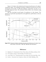
Using the Simpli®ed Stability Data shown in Diagram 3 (Figure 44.1), estimate
the amount of cargo (kg 3 m) which can be loaded so that after completion of
loading the ship does not have de®cient stability. Prior to loading the cargo the
following weights were already on board:
250 t fuel oil kg 0.5 m Free Surface Moment 1400 t m
50 t fresh water kg 5.0 m Free Surface Moment 500 t m
2000 t cargo kg 4.0 m
The light displacement is 1000 t, and the loaded Summer displacement is 3500 t
Since 10 875 tonnes metres is less than the maximum permissible deadweight
moment at a displacement of 3500 tonnes, the ship will not have de®cient
stability and may load 200 tonnes of cargo.
Ans.
Load 200 tonnes.
Example 2
Using the Maximum Permiss ible Deadweight Moment diagram 3 (Figure 44.1)
and the information given below, ®nd the quantity of timber deck cargo (Kg
8.0 m) which can be loaded, allowing 15 per cent for water absorption during
the voyage.
374 Ship Stability for Masters and Mates
Item Weight Kg Deadweight Moment
Light disp. 1000 t ± ±
Fuel oil 250 t 0.5 m 125 t m
Free surface ± ± 1400 t m
Fresh water 50 t 5.0 m 250 t m
Free surface ± ± 500 t m
Cargo 2000 t 4.0 m 8000 t m
Present cond. 3300 t 10 275 t m À Point 2
(Satisfactory)
Maximum balance 200 t 3.0 m 600 t m
Summer displ. 3500 10 875 t m À Point 3
(Satisfactory)
Simpli®ed stability information 375
Fig. 44.1
Summer displacement 4000 tonnes, Light Displacement 1000 tonnes.
Weights alre ady on board:
Fuel oil 200 tonnes, Kg 0.5 m, free surface moment 1400 t m
Fresh water 40 tonnes, Kg 5.0 m, free surface moment 600 t m
Cargo 2000 tonnes, Kg 4.0 m
Ballast 350 tonnes, Kg 0.5 m
The following weights will be consumed durin g the voyage:
Fuel oil 150 tonnes, Kg 0.5 m. Free surface moment will be
reduced by 800 t m
Fresh water 30 tonnes, Kg 5.0 m. Free surface moment will be
by 200 t m
Departure Condition
From diagram 3, where the line joining points 4 and 5 cuts the curve of
Maximum Permissible Deadweight Moments (point 6), the displacement is
3920 tonnes.
Total departure displacement 3920 tonnes
Departure displacement without deck cargo 3590 tonnes
; Max deck cargo to load 330 tonnes
Absorption during voyage
15
100
 330 49X5 tonnes
376 Ship Stability for Masters and Mates
Item Weight Kg Deadweight Moment
Light ship 1000 ± ±
Fuel oil 200 0.5 100
Free surface 1400
Fresh water 40 5.0 200
Free surface 600
Cargo 2000 4.0 8000
Ballast 350 0.5 175
Departure Disp. (without
deck cargo) 3590 10 475 ± Point 4
(Satisfactory)
Maximum deck cargo 410 8.0 3280
Summer disp. 4000 13 755 ± Point 5
(De®cient Stability)
Arrival Condition
Ans.
Load 330 tonnes of deck cargo.
Simpli®ed stability information 377
Item Weight Kg Deadweight Moment
Departure disp. without
deck cargo 3590 10 475
Fuel oil À 150 0.5 À75
Free Surface À800
Fresh water À30 5.0 À150
Free surface À200
Arrival disp. without
deck cargo 3410 9250
Deck cargo 330 8.0 2640
Absorption 49.5 8.0 396
Total arrival disp. 3789.5 12 286 ± Point 7
(Satisfactory Stability)
Exercise 44
1 Using the Maximum Permissible Deadweight Moment diagram 3, ®nd the
amount of deck cargo (kg 8.0 m) which can be loaded allowing 15 per cent
for water absoption during the voyage given the following data:
Light displacement 1000 tonnes, Loaded disp lacement 4000 tonnes.
Weights already on board:
During the voyage the following will be consumed (tonnes and kg):
Fuel oil 250 0.5 Reduction in free surface moment 850 t m.
Fresh water 40 5.0 Reduction in free surface moment 400 t m.
Item Weight Kg Free Surface Moment
Cargo 1800 4.0 ±
Fuel oil 350 0.5 1200
Fresh water 50 5.0 600
Ballast 250 0.5 ±
Appendix I
Standard
abbreviations and
symbols
K The keel.
B The centre of buoyancy when the ship is upright.
B
1
The centre of buoyancy when the ship is inclined.
BM The height of the transverse metacentre above the
centre of buoyancy.
BM
L
The height of the longitudinal metacentre above
the centre of buoyancy.
CB Centre of buoyancy.
G The original position of the centre of gravity.
G
1
The new position of the centre of gravity.
M The original position of the transve rse metacentre.
M
1
The new position of the transverse metacentre.
M
L
The longitudinal metacentre.
KB The height of the centre of buoyancy above the
keel.
KG The height of the centre of gravity above the keel.
Kg The height of the centre of gravity of an item
above keel.
KM The height of the transverse metacentre above the
keel.
GM Initial transverse metacentric height.
CF Centre of Flotation.
GZ The length of the righting lever about centre of
gravity.
KN The length of the righting lever about keel.
Vorj The ship's volume of displacement.
Wori The ship's weight of displacement.
w A weight to be loaded, discharged, or shifted.
e
Amidships. (The symbol
e
is shown on trim
diagrams).
L The ship's length.
D The ship's depth.
B The ship's maximum beam.
d The ship's draft.
F Forward, or centre of ¯otation.
A Aft.
M or m Metres.
C
w
The water-plane coef®cient.
C
b
Block coef®cient.
C
m
Coef®cient of midships area.
C
p
Prismatic coef®cient.
I or i Second moment of an area.
l The distance of the centre of ¯otation from aft.
P The upthrust on the keel blocks when drydocking.
m The permeability of a compartment.
WL The original waterline.
W
1
L
1
The new waterline.
G
v
The virtual centre of gravity.
t The trim.
MCTC or MCT 1 cm The moment to change the trim by 1 cm.
TPC The tonnes per centimetre immersion.
GM
L
The longitudinal metacentric height.
SG Speci®c gravity.
y An angle of list or heel.
WPA Area of a water-plane.
FWA Fresh water allowance.
FW Fresh water.
SW Salt water.
CDB Cellular double-bottom tank.
CI or h The common interval used in Simpson's Rules.
E Young's Modulus.
y Depth from the neutral layer.
f Stress.
q Shearing stress.
r Density in tonnes/m
3
.
r
FW
Fresh water density @ 1.000 t/m
3
.
r
SW
Salt water density @ 1.025 t/m
3
.
r
DW
Dock water density as given in t/m
3
.
d
max
Maximum squat.
S Blockage factor.
y Static underkeel clearance.
y
2
Dynamical underkeel clearance.
H Water depth relating to squat.
T Ship's mean draft relating to squat.
V
k
Speed of ship relative to the water.
Standard abbreviations and symbols 379
Appendix II
Summary of stability
formulae*
Form Coef®cients
Area of waterplane L Â B Â C
w
Area of amidships B Âd  C
m
Volume of displacement L  B  d  C
b
C
b
C
m
 C
p
Drafts
When displacement is constant: (For box-shapes):
New draft
Old draft
Old density
New density
When draft is constant:
New displacement
Old displacement
New density
Old density
TPC
WPA
97X56
FWA
W
4 Â TPC
Change of draft or
FWA 1025 À r
DW
25
Dock Water Allowance
Homogeneous log:
draft
depth
relative density of log
relative density of water
* See note on page 386.
Variable immersion hydrometer:
Density
M
y
M
y
À x
M
y
ÀM
x
L
Trim
MCTC
W Â GM
L
100 Â L
Change of trim
Trimming moment
MCTC
Change of draft aft
l
L
 Change of trim
Change of draft forward Change of trim
À Change of draft aft
Effect of trim on tank soundings:
Head when full
Length of tank
Trim
Length of ship
True Mean Draft:
Correction
FY
Trim
Length
To Keep the Draft Aft Constant:
d
MCTC Â L
TPC Â l
To ®nd GM
L
:
GM
L
GG
1
L
t
Simpson's Rules
1st Rule:
Area h/3 (a 4b 2c 4d e) or
1
3
 CI  S
1
2nd Rule:
Area 3h/8 (a 3b 3c 2d 3e 3f g) or
3
8
 CI  S
2
3rd Rule:
Area h/12 (5a 8b À c) or
1
12
 CI  S
3
Summary of stability formulae 381
KB and BM
Transverse Stability
For rectangular waterplanes:
I
LB
3
12
BM I/V
For box-shapes:
BM B
2
/12d
KB d/2
KM
min
Ba
6
p
For triangular prisms:
BM B
2
/6d
KB 2d/3
Depth of centre of buoyancy
1
3
d
2
V
A
below the waterline
Longitudinal Stability
For rectangular waterplanes:
I
L
BL
3
12
BM
L
I
L
V
For box-shapes:
BM
L
L
2
/12d
For triangular prisms:
BM
L
L
2
6d
Transverse Statical Stability
Moment of Statical Stability W Â GZ
At Small Angles of Heel:
GZ GM Â sin y
382 Ship Stability for Masters and Mates
By Wall-Sided Formula:
GZ GM
1
2
BM tan
2
ysin y
By Attwood's Formula:
GZ
v  hh
1
V
À BG sin y
Stability Curves:
New GZ Old GZ Æ GG
1
sin Heel or
New GZ KN À KG sin Heel
Dynamical Stability W Â Area under stability curve
W
v(gh g
1
h
1
)
V
À BG(1 À cos y)
!
List
Final KG
Final Moment
Final Displacement
GG
1
w  d
Final W
tan List
GG
1
GM
Increase in draft due to list:
New draft
1
2
EbEsin y (d À rcos y
Inclining Experiment:
GM
GG
1
Length of plumbline
Deflection
Effect of Free Surface
Virtual loss of GM
lb
3
12
Â
r
W
Â
1
n
2
Drydocking and Grounding
Upthrust at Stern:
P
MCTC Â t
l
or P Old À New displacement
Summary of stability formulae 383
Virtual loss of GM
P Â KM
W
or
P Â KG
W À P
Pressure of Liquids
Pressure (P) Dwg
Thrust P Â Area
Depth of centre of pressure
I
WL
AZ
Bilging and Permeability
Permeability
BS
SF
 100 per cent
Increase in draft
mv
A À ma
Strength of Ships
Stress
Load
Area
Strain
Change in length
Original length
y
R
Young's Modulus:
E
Stress
Strain
Bending Moment:
M
E
R
 I
Section Modulus
I
Y
Stress:
f
E
R
 y
384 Ship Stability for Masters and Mates
Shearing Stress:
q
FEAEy
IEt
Ship Squat
Blockage factor
b  T
B Â H
d
max
C
B
 S
0X81
 V
k
2X08
20
y
o
H À T
y
2
y
o
À d
max
In open water:
d
max
C
B
 V
2
k
100
In con®ned channel:
d
max
C
B
 V
2
k
50
Width of Influence 7X7 20 1 À C
B
2
Miscellaneous
Angle of Loll:
tan loll
2GM
BM
r
GM
2 Â Initial GM
cos loll
Heel Due to Turning:
tan Heel
v
2
 BG
gErEGM
Rolling Period:
T 2p
k
gEGM
p
2k
GM
p
approx.
Summary of stability formulae 385
Zero GM:
tan list
2EwEd
W Â BM
3
r
Theorem of Parallel Axes:
I
CG
I
OZ
À Ay
2
or I
NA
I
xx
À Ay
2
Summary
Always write your formula ®rst in letters. If you then make a mathematical
error you will at least obtain some marks for a correct formula.
386 Ship Stability for Masters and Mates
Appendix III
Conversion tables
Metric-Imperial Imperial-Metric
1m 3X281 ft
1m 39X37 ins
1m
2
10X764 ft
2
1m
3
11X77 ft
3
1 litre 61X02 ins
3
1 litre 1X76 pints
1 litre 0X22 galls
1 tonne 0X985 tons
1kg 2X205 lbs
1m
3
atonne 35X88 ft
3
aton
1 litreakg 0X016 ft
3
alb
1000 kgam
3
1000 ozaft
3
1025 kgam
3
1025 ozaft
3
1ft 0X3048 m
1in 25X4mm
1ft
2
0X0929 m
2
1in
2
645X2mm
2
40 ft
3
1X133 m
3
100 ft
3
2X832 m
3
1ft
3
0X02832 m
3
1 gall 4X5461 litres
1t 1X016 tonne
1lb 0X4536 kg
1 cwt 50X80 kg
1ft
3
at 0X02787 m
3
atonne
1ft
3
alb 62X428 litresakg
1000 ozaft
3
1000 kgam
3
1025 ozaft
3
1025 kgam
3
TPI
HH
 0X4 TPC
MCTI
HH
 0X12 MCTC
1 tonain
2
 15X444 1MNam
2
1 lbf 4X448 N
MNam
2
 100 tonnesam
2
Appendix IV
Extracts from the
M.S. (Load Lines)
Rules, 1968
Part V
GENERAL
Information as to stability of ships
30 (1) The owner of an y ship to which freeboards are assigned under these
Rules shall provide for the guidance of the master of the ship information
relating to the stability of the ship in accordance with the following
provisions of this Rule.
(2) Except as otherwise provided in paragraph (6) of this Rule, such
information shall include particulars appropriate to the ship in respect of
all matters speci®ed in Schedule 7 to these Rules and shall be in the form
required by that Schedule.
(3) Subject to the following paragraph, the information shall, when ®rst
supplied, be based on the determination of stability by means of an
inclining test which shall unless the Board otherwise permits be carried
out in the presence of a surveyor appointed by the Board. The information
®rst supplied shall be replaced by fresh information whenever its accuracy is
materially affected by alteration of the ship. Such fresh information shall if
the Board so require be based on a further inclining test.
(4) The Board may:
(a) in the case of any ship allow the information to be based on the
determination, by means of an inclining test, of the stability of a sister
ship;
(b) in the case of a ship specially designed for the carriage of liquids or
ore in bulk; or of any class of such ships, dispense with an inclining
test if satis®ed from the informati on available in respect of similar
ships that the ship's proportions and arrangements are such as to
ensure more than suf®cient stability in all probable loading con-
ditions.
(5) The information, and any fresh information to replace the same
pursuant to paragraph (3) of this Rule, shall before issue to the master be
submitted by or on behalf of the owner of the ship to the Board for their
approval, together with a copy thereof for retention by the Board, and shall
incorporate such additions and amendments as the Board may in any
particular case require.
(6) (a) The owner of any ship which, by virtue of the Merchan t Shipping
(Load Lines) (Transitional Provisions) Regulations 1968, is to be
treated as a ship to which freeboards have been assigned under
these Rules shall provide for the information of the master such
information relating to the stability of the ship as was required to be
so provided under the law in force immediately prior to the coming
into operation of these Rules (a).
(b) The requirement in the preceding sub-paragraph shall have effect in
relation to any ship to which it applies until the date on which the
load line certi®cate currently in force in respect of the ship on the
date these Rules come into operation ceases to be valid.
(7) Informa tion provided pursuant to the foregoing provisions of this Rule
shall be furnished by the owner of the ship to the master in the form of a
book which shall be kept on the ship at all times in the custody of the
master.
Information as to loading and ballasting of ships
31 (1) The owner of an y ship to which freeboards are assigned under these
Rules, being a ship of more than 150 metres in length specially designed for
the carriage of liquids or ore in bulk, shall provide for the information of the
master information relating to the loading and ballasting of the ship in
accordance with the following provisions of this Rule.
(2) Such information shall consist of worki ng instructions specifying in
detail the manner in which the ship is to be loaded and ballasted so as to
avoid the creation of unacceptable stresses in her structure and shall indicate
the maximum stresses permissible for the ship.
(3) The provisions of paragraph (5) of the preceding Rule shall have effect
in respect of information required under this Rule, and the information duly
approved in accordance with that paragraph shall be contained in the book
to be furnished to the master of the ship pursuant to paragraph (7) of that
Rule, so however that the information to be provided pursuant to each Rule
is separately shown in the book under separate headings specifying the
number and heading of each Rule.
Extracts from the M.S. (Load Lines) Rules, 1968 389
Part 1
SHIPS IN GENERAL
Structural Strength and Stability
2 (1) The construction of the ship shall be such that her general structural
strength will be suf®cient for the freeboards to be assigned to her.
(a) See section 18 of the Merchan t Shipping (Safety Convention) Act
1949 (12,13 & 14 Geo. 6 c 43.) and section 14 of the Merchant
Shipping Act 1964 (1964 c 47).
(2) The design and construction of the ship shall be such as to ensure that
her stability in all probable loading conditions will be suf®cient for the
freeboards to be assigned to her, and for this purpose regard shall be had, in
addition to the intended service of the ship and to any relevant
requirements of Rules made under the Merchant Shipping (Safety
Convention) Act 1949(a) and the Merchant Shipping Act 1964( b), to the
following criteria:
(a) The Area under the curve of Righting Levers (GZ curve) shall not be
less than:
(i) 0.055 metre-radians up to an angle of 30 degrees;
(ii) 0.09 metre-radians up to an angle of either 40 degrees or the
angle at which the lower edges of any openings in the hull,
superstructures or deckhouses, being openings which cannot be
closed weathertight, are immersed if that angle be less;
(iii) 0.03 metre-radians between the angles of heel of 30 degrees and
40 degrees or such lesser angle as is referred to in (ii).
(b) The Righting Lever (GZ) shall be at least 0.20 metres at an angle of
heel equal to or greater than 30 degrees.
(c) The maximum Righting Lever (GZ) shall occur at an angle of heel not
less than 30 degrees.
(d) The initial transverse metacentric height shall not be less than 0.15
metres. In the case of a ship carrying a timber deck cargo which
complies with sub-paragraph (a) by taking into account the volume
of timber deck cargo the initial transverse metacentric height shall
not be less than 0.05 metres.
(3) To determine whether the ship complies with the requirements of sub-
paragraph (2) the ship shall, unless the Board otherwise permit, be subjected
to an inclining test carried out in the presence of a surveyor appointed by
the Board, and the Board shall notify the Assigning Authority whether or
not they are satis®ed that the ship complies with those requirements.
(a) 1949 12, 13 & 14 Geo. 6 c. 43.
(b) 1964 c. 47.
390 Ship Stability for Masters and Mates
SCHEDULE 7
Information as to Stability of Ships
(Rule 30)
The information relating to the stability of a ship to be provided for the
master pursuant to Rule 30 of these Rules shall include particulars
appropriate to the ship of the matters speci®ed below. Such particulars
shall be in the form of a statement unless the contrary is indicated.
1. The ship's name, of®cial number, port of registry, gross and register
tonnages, principal dimensions, displacement, deadweight and draft to the
Summer load line.
2. A pro®le view and, if the Board so require in a particular case, plan views
of the ship drawn to scale showing with their names all compartments,
tanks, storerooms and crew and passenger accommodation spaces, and also
showing the mid-length position.
3. The capacity and the centre of gravity (longitudinally and vertically) of
every compartment available for the carriage of cargo, fuel, stores, feed
water domestic water or water ballast. In the case of a vehicle ferry, the
vertical centre of gravity of compartments for the carriage of vehicles shall
be based on the estimated centres of gravity of the vehicles and not on the
volumetric centres of the compartments.
4. The estimated total weight of (a) passengers and their effects and (b)
crew and their effects, and the centre of gravity (longitudinally and
vertically) of each such total weight. In assessi ng such centres of gravity
passengers and crew shall be assumed to be distributed about the ship in
the spaces they will normally occupy, including the highest decks to which
either or both have access.
5. The estimated weight and the disposition and centre of gravity of the
maximum amount of deck cargo which the ship may reasonably be
expected to carry on an exposed deck. The estimated weight shall include
in the case of deck cargo likely to absorb water the estimated weight of
water likely to be so absorbed and allowed for in arrival conditions, such
weight in the case of timber deck cargo being taken to be 15 per cent by
weight.
6. A diagram or scale showing the load line mark and load lines with
particulars of the corresponding freeboards, and also showing the displace-
ment, metric tons per centimetre immersion, and deadweight corresponding
in each case to a range of mean draughts extending between the waterline
representing the deepest load line and the waterline of the ship in light
condition.
7. A diagram or tabular statement showing the hydrostatic particulars of
the ship, including:
(1) the heights of the transverse metacentre and
(2) the values of the moment to change trim one centimetre,
Extracts from the M.S. (Load Lines) Rules, 1968 391
for a range of mean drafts extending at least between the waterline
representing the deepest load line and the waterline of the ship in light
condition. Where a tabular statement is used, the intervals between such
drafts shall be suf®ciently close to permit accurate interpolation. In the case
of ships having raked keels, the same datum for the heights of centres of
buoyancy and metacentres shall be used as for the centres of gravity
referred to in paragraphs 3, 4 and 5.
8. The effect on stability of free surface in each tank in the ship in which
liquids may be carried, including an example to show how the metacentric
height is to be corrected.
9 (1) A diagram showing cross curves of stability indicating the height of
the assumed axis from which the Righting Levers are measured and the trim
which has been assumed. In the case of ships having raked keels, where a
datum other than the top of keel has been used the position of the assumed
axis shall be clearly de®ned.
(2) Subject to the following sub-paragraph, only (a) enclosed super-
structures and (b) ef®cient trunks as de®ned in paragraph 10 of Schedule
5 shall be taken into account in deriving such curves.
(3) The following structures may be taken into account in deriving such
curves if the Board are satis®ed that their location, integrity and means of
closure will contribute to the ship's stability:
(a) Superstructu res located above the superstructure deck;
(b) deckhouses on or above the freeboard d eck, whether wholly or in
part only;
(c) hatchway structures on or above the freeboard deck.
Additionally, in the case of a ship carrying timber deck cargo, the volume
of the timber deck cargo, or a part thereof, may with the Board's approval
be taken into account in deriving a supplementary curve of stability
appropriate to the ship when carrying such cargo.
(4) An example shall be given showing how to obtain a curve of Righting
Levers (GZ) from the cross curves of stability.
(5) Where the buoyancy of a superstructure is to be taken into account in
the calculation of stability information to be supplied in the case of a vehicle
ferry or similar ship having bow doors, ship's side doors or stern doors,
there shall be included in the stability information a speci®c statement that
such doors must be secured weather-tight before the ship proceeds to sea
and that the cross curves of stability are based upon the assumption that
such doors have been so secured.
10 (1) The diagram and statements referred to in sub-paragraph (2) of this
paragraph shall be provided separately for each of the following conditions
of the ship:-
(a) Light condition. If the ship has permanent ballast, such diagram and
statements shall be provided for the ship in light condition both (i)
with such ballast, and (ii) without such ballast.
392 Ship Stability for Masters and Mates
(b) Ballast condition, both (i) on departure, and (ii) on arrival, it being
assumed for the purpose of the latter in this and the following sub-
paragraphs that oil fuel, fresh water, consumable stores and the like
are reduced to 10 per cent of their capacity.
(c) Condition both (i) on departure, and (ii) on arrival, when loaded to
the Summer load line with cargo ®lling all spaces available for cargo,
cargo for this purpose being taken to be homogeneous cargo except
where this is clearly inappropriate, for example in the case of cargo
spaces in a ship which are intended to be used exclusively for the
carriage of vehicles or of containers.
(d) Service loaded conditions, both (i) on departure and (ii) on arrival.
(2) (a) A pro®le diagram of the ship drawn to a suitable small scale
showing the disposition of all components of the deadweight.
(b) A statement showing the lightweight, the disposition and the total
weights of all components of the deadweight, the displacement, the
corresponding positions of the centre of gravity, the metacentre and
also the metacentric height (GM).
(c) A diagram showing a curve of Righting Levers (GZ) derived from the
cross curves of stability referred to in paragraph 9. Where credit is
shown for the buoyancy of a timber deck cargo the curve of
Righting Levers (GZ) must be drawn both with and without this
credit.
(3) The metacentric height and the curve of Righting Levers (GZ) shall be
corrected for liquid free surface.
(4) Where there is a signi®cant amount of trim in any of the conditions
referred to in sub-parag raph (1) the metacentric height and the curve of
Righting Levers (GZ) may be required to be determined from the trimmed
waterline.
(5) If in the opinion of the Board the stability characteristics in either or
both of the conditions referred to in sub-paragraph (1)(c) are not
satisfactory, such conditions shall be marked accordingly and an appro-
priate warning to the master shall be inserted.
11. Where special procedures such as partly ®lling or completely ®lling
particular spaces designated for cargo, fuel, fresh water or other purposes
are necessary to maintain adequate stability, a statement of instructions as
to the appropriate procedure in each case.
12. A copy of the report on the inclining test and of the calculation
therefrom of the light condition particulars.
Merchant Shipping (Safety Convention) Act, 1949
Section 18-( 1) There shall be carried on board every British ship registered
in the United Kingdom whose keel is laid after the commencement of this
Extracts from the M.S. (Load Lines) Rules, 1968 393
Act such information in writing about the ship's stability as is necessary for
the guidance of the master in loading and ballasting the ship.
(2) The said information shall be in such a form as may be approved by the
Minister (who may approve the provision of the information in the form of
a diagram or drawing only), and shall be based on the determination of the
ship's stability by means of an inclining test of the ship:
Provided that the Minister may allow the information to be based on a
similar determination of the stability of a sister ship.
(3) When any information under this section is provided for any ship, the
owner shall send a copy thereof to the Minister:
Provided that the owner shall not be required to send a copy of any
information to the Minister if a previous copy of the same information has
been sent to the Minister.
(4) If any such ship proceeds, or attempts to proceed, to sea without such
information as aforesaid on board, the owner or master of the ship shall be
liable to a ®ne not exceeding one hundred pounds; and if the owner of any
ship contravenes the last preceding subsection, he shall be liable to a like
®ne.
(5) It is hereby declared that for the purposes of section two hundred and
®fty-eight of the principal Act (which requires documents relating to
navigation to be delivered by the master of a ship to his successor)
information under this section shall be deemed to be a document relating to
the navigation of the ship.
Section 29-(l) Nothing in this Act:
(c) requiring information about a ship's stability to be carried on board;
shall, unless in the case of information about a ship's stability the
Minister otherwise orders, apply to any troopship, pleasure yacht or
®shing vessel, or to any ship of less than ®ve hundred tons gross
tonnage other than a passenger steamer or to any ship not
propelled by mechanical means.
394 Ship Stability for Masters and Mates
Appendix V
Department of
Transport Syllabuses
(Revised April 1995)*
Supplied kindly by Marine Safety Agency (MSA) of Southampton and
Scottish Quali®cations Authority (SQA) of Glasgow.
CLASS 5 CERTIFICATE OF COMPETENCY
General Ship Knowledge ± MSA/SQA
(a) General ideas on ship construction and on plans available on board
ship.
General pumping arrangements.
General de®nition of main dimensions.
The names of the principal parts of a ship.
(b) General understanding of:
Displacement;
Deadweight;
Buoyancy; Reserve buoyancy.
Use of displacement and tonnes per centimetre immersion scales to
determine weight of cargo or ballast from draughts or freeboard.
Load line marks.
Effect of density of water on draught and freeboard.
Fresh water allowance.
(c) (i) General understanding of:
Centre of gravity
Centre of buoyancy
Metacentric height
Righting lever
Righting moment
(ii) The use of stability and hydrostatic data supplied to ships,
including stability data in simpli®ed form.
* All of these syllabuses to be reviewed and possibly revised by MSA in 1999/2000.
The effect of adding and removing weights. The danger of slack
tanks.
(iii) Rigging a ship for loading and discharging cargo, the use of
derricks, winches and cranes.
`Lining up' pipelines on oil products carriers.
The stowage and securing of cargoes including bulk cargoes.
Grain cargoes, timber cargoes and ro-ro cargoes. A knowledge of
the safety precautions to be taken during the loading and
discharging of bulk oil, chemicals and other dangerous commod-
ities.
Ventilation systems of holds and tanks. Entry into enclosed spaces.
CLASS 4 CERTIFICATE OF COMPETENCY
General Ship Knowledge ± BTEC/SQA/HND Part 1
(a) General ideas on ship construction and on plans available onboard ship.
General de®nitions of main dimensions.
The names of the principal parts of a ship.
The candidate will be expected to show his practical acquaintance with:
Longitudinal and transverse framing
Beams and beam knees
Watertight bulkheads
Hatchways and closing appliances
Rudders
Steering gear
Shell and deck plating
Double bottoms and peak tanks
Bilges
Side and wing tanks
Stern frames
Propellers and propeller shafts
Stern tubes
Sounding pipes
Air pipes
General pumping arrangements
The stiffening and strengthening to resist panting, pounding and
longitudinal stresses.
Cause and prevention of corrosion in a ship's structure.
(b) General ideas on welding, riveting and burning and the precautions to
be taken when such processes are carried out aboard ship.
(c) (i) The meaning of the terms: Block co-ef®cient; Displacement;
Deadweight.
(ii) Density, relative density; Principle of Archimedes; ¯otation. Effect
of density of water on draught and freeboard. Fresh water
allowance. The marine hydrometer and its uses.
396 Ship Stability for Masters and Mates
(d) Care and maintenance of all life saving and ®re ®ghting appliances,
lights and sound signalling apparatus.
(e) The computation of areas by Simpson's First and Second Rules.
CLASS 4 CERTIFICATE OF COMPETENCY
Cargo Operations and Stability ± MSA/SQA
(a) Use of displacement and tonnes per centimetre immersion scales to
determine weight of cargo or ballast from draughts or freeboard.
Load line-marks.
Buoyancy; Reserve buoyancy; understanding of fundamental actions to
be taken in the event of partial loss of intact buoyancy.
(b) (i) General understanding with de®nitions of:
Centre of gravity, stable, unstable and neutral equilibrium.
Centre of buoyancy
Metacentric height
Righting lever
Righting moment
(ii) The use of stability and hydrostatic data supplied to ships.
The effect of adding and removing weights.
The danger of slack tanks. Security of hatches.
(iii) Rigging a ship for loading and discharging cargo, the use of
derricks, winches and cranes.
`Lining up' pipelines on oil products carriers.
The stowage, separation and dunnaging of cargoes including bulk
cargoes, timber cargoes; grain cargoes, ro-ro cargoes.
Causes of sweating, and precautions to be taken before, during
and after stowing to prevent damage by sweat.
A knowledge of the safety precautions to be taken during the
loading and discharge of bulk oil, chemicals and other dangerous
commodities, Calculations of weight capacities taken up by part
cargoes and of space remaining.
Conversion of weight measurement of cargo into space measure-
ment and vice versa.
The making and use of cargo plans.
Ventilation and systems of holds and tanks.
Precautions to be taken before entering cargo and ballast tanks
and void spaces. The carriage of passengers and livestock.
CLASS 2 CERTIFICATE OF COMPETENCY
Ship Construction ± BTEC/SQA/HND
(a) Types of ships. General ideas on strength and construction in relation
to particular trades, including specialised carriers.
Department of Transport Syllabuses 397
The use of special steels, aluminium and ®re resistant materials in ship
construction.
(b) Midship sections of single deck and 'tween deck ships, including bulk
carriers, container ships and specialised carriers. Functions, construction
and stiffening of watertight bulkheads, including collision bulkhead.
Structure at the stern, construction, stiffening and closing arrangements
of hatchways and superstructures, tank openings, watertight and hull
doors.
(c) General ideas on welding processes in construction and repair work,
types of weld, common faults, visual examination of welded work.
Testing of tanks and other watertight work.
Methods of corrosion control.
(d) Stresses produced by shear and bending. To produce simple curves of
load, shear force and bending moments. Torsional stress. Modern
methods of determining the effect of different conditions of loading
and ballasting on the ship's structure. Methods of compensating for
discontinuity of strength. Local and speci®c stiffening.
(e) Classi®cation of ships; periodic surveys for retention of class. The
Cargo Ship Construction and Survey Rules and surveys required under
the Rules.
CLASS 2 CERTIFICATE OF COMPETENCY
Ship Stability ± MSA/SQA
(a) Determination of the position of the centre of gravity of a ship for
different conditions of loading and ballasting. The effect on the position
of the centre of gravity of adding, removing, shifting or suspending
weights. To determine the virtual rise in the position of the centre of
gravity due to slack tanks. Transverse and longitudinal metacentres,
metacentric height. Initial stability and its limitation to small angles of
inclination. Changes in stability during a voyage. Effects of a shift of
cargo or solid ballast. Stiff and tender ships.
(b) Changes of trim and draught due to loading, discharging and shifting
weights. Effects of list and trim on stability. Stability and trim when
drydocking.
(c) Stability to moderate for large angles of heel; assessment of dynamical
stability from GZ curve; angle of loll; shifting or adding weights with
zero GM; effect of wind and wave excitation.
(d) Dangers to a ship with a heavy list. Precautions when righting. Deck
cargoes, homogeneous cargo and cargo liable to shift. Ballasting for
stability consideration. The effect of beam and freeboard on stability.
(e) The inclining experiment. A comprehensive knowledge of the hydro-
static, stability and stress data supplied to ships.
(f) An understanding of the factors affecting the shape of a curve of
statical stability and the signi®cance of the area under the curv e,
including its calculation. Use of simpli®ed data. Grain shift moments.
398 Ship Stability for Masters and Mates
![ship stability for masters and mates [electronic resource]](https://media.store123doc.com/images/document/14/y/bj/medium_bjc1401370968.jpg)