Know and Understand Centrifugal Pumps Episode 5 pps
Bạn đang xem bản rút gọn của tài liệu. Xem và tải ngay bản đầy đủ của tài liệu tại đây (708 KB, 20 trang )
Know and Understand Centrifugal Pumps
~ ~~ ~ ~ ~~ ~~~~~ ~~~ ~ ~~~ ~~
Figure
6-12
~ ~~~
w
The can may fracture
(see
advantages).
w
Less
efficient than conventional pumps.
w
May consume more energy
(BHP)
than conventional pumps.
w
Cannot
see
the direction of rotation.
Pump impellers
The pump impeller receives the pumped liquid and imparts velocity
to
it
with help from the electric motor, or driver. The impeller itself looks
like a modified boat or airplane propeller. Actually, boat propellers are
axial flow impellers. Airplane propellers are axial flow impellers also,
except that they are adapted
to
handle air.
As
a general rule, the velocity (speed) of the impeller and the diameter
of the impeller, will determine the head or pressure that the pump can
generate. As a general rule, the velocity and the height of the impeller
blades, will determine the
flow
(gpm) that the pump can generate
(Figure
6-1
3).
Remember that pumps don't actually generate flow (no pump in the
world can convert three gallons per minute at the suction nozzle into
four gallons per minute out of the discharge nozzle), but this is the
term used in the industry.
Pump impellers have some different design characteristics. Among
n
64
6
Pump
Classification
____
DIAMETER AND
HEIGHTOFTHE
VANESANDSPEED
DETERMINE
THE
FLOW
-~
Figure
6-13
them is the way that the impeller receives the liquid from the suction
piping. A classic pump impeller receives the liquid at the impeller’s ID.
By
centrifugal force and blade design, the liquid is moved through the
blades fi-om the ID
to
the OD
of
the impeller where it expels the liquid
into the volute channel.
__
Tu
r
b
i
ne
i
m
pel
I
ers
On the other hand, turbine impellers receive the liquid at the outside
diameter of the impeller, add velocity fi-om the motor, and then expel
the liquid, also at the
OD
to
the discharge nozzle. Because these
impellers have little available area at the OD, these impellers don’t
move large quantities
of
liquid. Rut, because the liquid’s velocity is
jerked instantly and violently
to
a very high speed (remember that
a
classic centrifugal pump has
to
accelerate
the liquid across the blades
from the ID
to
the
OD),
a lot of energy is added
to
the fluid and these
type pumps are capable of generating
a
lot of head at a low flow.
Additionally, because all the action occurs at the impeller’s OD
(Remember that there are friction losses and drag as the liquid in
a
centrifugal pump traverses the impeller blades from ID
to
OD), there
are minimal losses in a turbine pump impeller, which further adds
to
its
high-pressure capacity,
see
Figure
6-14.
In the case
of
a
regenerative
turbine
pump,
any high-energy liquid
that doesn’t leave the pump through the discharge nozzle is imme-
diately re-circulated back toward the suction where it combines with
any new liquid entering into the blades. In this case even more energy is
added
to
already high-energy liquid (thus the name ‘regenerative’).
This type pump continues
to
regenerate and compound its pressure or
Know and Understand Centrifugal Pumps
i
1
-
.~
-
~-
~~
~ ~~
Figure
6-14
~
~-
discharge head. It makes for a small piece of iron that packs an amazing
punch. Regenerative turbine pumps are found on industrial high-
pressure washers and enjoy a well-earned reputation as
a
feed water
pump on package boilers.
~___
___
Convent ion
a
I
i
m
pe
I I
ers
__
However, most conventional pump impellers receive the fluid into the
impeller eye,
at
the center or inside diameter of the impeller. There are
single suction impellers, and dual or double suction impellers with
two
eyes, one
on
each side. Dual suction impellers are mostly specified for
low NPSH applications because the eye area is doubled
(it
can receive
twice as much fluid
at
a
lower velocity head). Dual suction impellers arc
mostly found on split case pumps where the shaft passes completely
through the impeller. But they can also
be
found mounted onto the
end
of
the shaft in some special pump designs.
~~__
Suction specific speed,
Nss
~~
The
way that
a
pump receives the liquid into the impeller determines
the available combination of discharge flow and head that the pump can
generate. Essentially,
it
determines the operating window of the pump.
66
-
1
Pump
Classification
This operating window is quantified or rated by the term 'Suction
Specific Speed,
Nss'.
The
Nss
is calculated with three parameters, the
speed, the flow rate, and the NPSHr. These numbers come from
the pump's performance curve, discussed in Chapter
7.
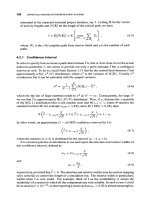
The formula is
the following:
Where:
N
=
the speed of the pump/motor in revolutions per minute
Q
=
the square root
of
the flow in gallons per minute at the
Best Efficiency Point BEP. For double suction pumps, use
'/2
REP Flow.
by the pump at the REP.
NPSHr
=
the net positive suction head required
~~~~ ~~ ~~~
For the purposes of understanding this concept and formula, there's nothing
mathematically significant about the square root of the flow, or the NPSHr to the
3/4
power. These mathematical manipulations simply give
us
Nss values that are easily
understood and recognizable. For example, the health inspector might judge a
restaurant's cleanliness on a scale from
1
to
100.
We might ask
you
to rate this book
on a scale from
1
to 10. Those are easy numbers to deal with. How would
you
rate
this book on
a
scale from 2,369 to 26,426,851?This doesn't make sense. Likewise, the
mathematical manipulations
in
the
Nss
formula serve simply to convert weird values
into a scale from 1,000 to
20,000
that cover most impellers and pumps. Values at
1,000
and
20,000
are on the outer fringes. Most pumps register an Nss between
7,000
and
14,000
on a relative scale that is easily understood and comparable to
other Nss values of competing pumps, similar pumps, and totally different pumps.
The
Nss
value is a dimensionless number relating the speed, flow and
NPSHr into an operating window that can be expected from a pump. It
is
an index or goal used by pump design engineers. Consulting
engineers use the
Nss
when comparing similar pumps for correct
selection into an application. Once the pump is installed,
it
becomes a
valuable tool for the process engineer, and for the operators interested
in keeping the pump running without problems. The
Nss
is an
indication of the pump's ability
to
operate away from its design point,
called the REP, without damaging the pump.
The
Nss
value is really simple, although often
it
is made
to
appear
complicated. The
Nss
is an equation with a numerator and
a
denominator. The
Nss
value is obtained by dividing the numerator by
the denominator.
Know and Understand Centrifugal Pumps
The operator of
a
car
would know the limits of his automobile. He
would
or should
know if the car
is
capable of operating safely before launching out on a cross-country
trip at highway speeds. He should know how much weight the car can carry safely in
the trunk. He should have
a
general idea
if
he’s getting the expected gasoline mileage
from his car. Right? Likewise, the process engineer (and operators) of an industrial
pump should know the operating window of the pump. RIGHT?
In the numerator we have the speed and the flow. If we were comparing
similar pumps into an application, these multiplied numbers would
mostly be a constant. In the denominator we have the NPSHr of the
pump (or competing pumps under comparison for an application).
As
the NPSHr of the pump
goes
down, the Nss value rises.
As
the Nss
value increases,
the
operating window of the pump narrows.
Some pump companies will promote and tout their low Nss values.
Sometimes
a
specification engineer will establish a maximum Nss limit
for quoted pumps. Let’s consider these examples of operating
parameters of pumps, and determine the
Nss.
These values are lifted
from the pump performance curves at the
BEP.
Para meters Example
1
Example
2
Example
3
Centrifugal Pump End Suction pump, End Suction, Single Dual Suction Impeller,
Type/ Liquid
Single Stage, ANSI
Stage,
API
#
610 Single Stage, NFPA
Spec/ Cooling Water SpeclKerosene Code/ Firewater
Pump/Motor Speed 1,750 rpm. 3,500 rpm. 1,780 rpm.
Flow 600 gprn. 1,200 gprn. 4,500 gpm.
NPSHr
a
BEP. 7 feet 30 feet 20 feet
Nss
1750
x
4600
=
9,961
3500
x
=
9,458
1780
x
GO
=
8,928
73/4 303/4 203/4
By
using these Nss values, we can interpret the Nss Graph, and get a
picture of the operating window of these three pumps.
To
interpret the
graph we start on the left column at the flow in gpm. In Figure
6-15,
we draw a line from the flow
to
the Nss value of the pump, and then
reference downward for water, or upward for hydrocarbons.
For the first example, the line terminates at
42%.
This means
DO
NOT
Pump
CI
assi fica
ti
o
n
HYDROCARBONS
MINIMUM CONTINUOUS
FLOW
AS
%
OF
BEP
FLOW
ON NON-TRIMMED IMPELLER.
USE
1/2
BEP
FLOW
FOR DOUBLE SUCTION IMPELLERS
100
200
300
400
500
600
700
800
900
1
.ooo
2.000
3.000
4.000
5.000
6.000
7.000
8.000
9.000
10.000
20.000
30.000
WATER BASED LIQUIDS
MINIMUM CONTINUOUS
FLOWAS
%
OF
BEP
FLOW
ON
FULL
SIZED IMPELLER.
FOR DOUBLE SUCTION IMPELLERS, USE
1/2
BEP FLOW
___
~~~
Figure
6-15
operate this pump
at
less than
42%
of the
REP.
42%
of
600
gpm is
252
gpm. The operator of this pump should not throttle a control valve and
restrict this pump at
less
than
252
gpm. If the operator throttles this
pump
to
240
gpm, and goes
to
lunch, he’ll probably have an
emergency when he returns from his lunch break. Actually this failure
would
be
an operation-induced failure. If you’re mistreating your car,
you cannot blame the mechanic.
In the Second example, the line terminates at
29%.
This means
DO
NOT operate this pump at less than
29%
of the
BEP.
29%
of
1200
gprn
69
Know and Understand Centrifugal Pumps
is
348
gpm. The process engineer should instruct the operators
to
always maintain the flow above
350
gpm unless he's prepared for pump
failure and stalled production.
In the third example, the line terminates at
53%.
This means
DO
NOT
run this pump
at
less
than
53%
of the
BEP.
53%
of
4500
gpm is
2385
gpm. Because this is a firewater pump and because firemen need
to
throttle the nozzles on their fire hoses, then we need
to
install
a
pressure relief valve on this system with a discharge bypass line
so
that
the pump dumps the restricted water (less than
2400
gpm) back into
the suction tank
or
lake. If not, this firewater pump is likely
to
suffer
bearing failure during an emergency.
The operating window is the effective zone around the REP on the
pump curve that must be respected by the process engineer and/or the
operators of the pump. How far away from the
BEP
a pump can
operate on its performance curve without damage is determined by its
impellers suction specific speed.
~
~-
-~
Open impellers
Impellers are also classified as
to
whether they are:
1.
Totally open,
2.
Semi-open (also called Semi-enclosed), and
3.
Totally enclosed.
Most totally open impellers are found on axial flow pumps.
This type of impeller would be used in
a
somewhat conventional
appearing pump
to
perform a chopping, grinding, or macerating action
~ __
Figure
6-16
Pump
Classification
on the liquid. The blade in the bottom of the kitchen blender is
a
macerating axial flow totally open impeller. The totally open axial flow
impeller moves
a
lot of volume flow (gpm), but not a
lot
of head or
pressure. With its open tolerances for moving and grinding solids, they
are generally not high efficiency devices.
~~~~
Semi open impeller
~~ ~
A
semi-open impeller has exposed blades, but with a support plate or
shroud on one side. Some people prefer the name semi-enclosed. These
types of impeller are generally used for liquids with a small percentage
of solid particles like sediment from the bottom of a tank or river, or
crystals mixed with the liquid (Figure
6-17).
__
Figure
6-17
The efficiency of these impellers is governed by the limited free space or
tolerance between the front leading edge of the blades and the internal
pump housing wall. Some pumps have a micrometer gauged jack bolt
arrangement on the axial bearing for performing an impeller setting.
The impeller setting corrects for erosion wear and thermal expansion in
this tight tolerance, returning the pump
to
its original efficiency.
~~
__
~
Totally
enclosed impeller
~~
Totally enclosed impellers are designed with the blades between
two
support shrouds or plates. These impellers are for totally clean liquids
because tolerances are tight at the eye and the housing, and there is no
room for suspended solids, crystals or sediment, see Figure 6-18.
Know and Understand Centrifugal Pumps
._
~
~-
Figure
6-18
Solid contamination will destroy the tolerance between the
OD
of the
eye and the bore of the pump housing.
This specific tolerance governs the efficiency
of
the pump.
The tolerance between the
OD
of the impeller eye and the internal
bore of the pump housing is set at the factory based on the temperature
of
the application and thermal growth of the pump metallurgy. This
tolerance tends
to
open with time for
a
number of reasons.
Among
them: erosion due
to
the passage of fluid, the lubricating nature
of
the
liquid, suspended solids and sediment will accelerate the wear,
cavitation damage, play in the bearings, bent shafts and unbalanced
rotary assemblies, and any hydraulic side loading on the shaft and
impeller assembly.
~~
~~
~~
Wear
bands
~ ~~~
Some pump companies will design replaceable wear bands for the
OD
of the impeller eye and
the
bore of the pump housing. It’s said that the
pump loses
1.5%
to
2%
efficiency points for every one thousandths wear
in a wear band beyond the factory setting. Therefore, by changing wear
bands, the pump is returned
to
its original efficiency. Because of this,
the term wear band is a misnomer.
A
better term would be ‘efficiency
band’ (Figure
6-19).
The replaceable wear bands can also be made in a machine shop in a
pump maintenance function. It is important that the new wear band
material is made of a non-galling, and non-sparking material softer than
the pump housing metallurgy. Plastic, composite, fiberglass and carbon
graphite wear band are perfectly good.
Be sure the material is
compatible with the pump’s metallurgy and the pumped liquid. It’s not
rn
72
7
.
Pump
Classification
\-
Flow
Impeller Wear Band
Figure
6-19
necessary that they be made of metal. Remember that their function is
not
to
wear, but
to
control the tolerance and efficiency of the pump.
Specific speed,
Ns
-
~-
Another distinction in impellers is the way the liquid traverses and
leaves the impeller blades. This is called the Specific Speed, Ns. It is
another index used by pump designers
to
describe the geometry of the
impeller and
to
classify impellers according
to
their design type and
application. By definition, the Specific Speed, Ns is the revolutions per
minute (rpm) at which
a
geometrically similar impeller would run if it
were of such a size as
to
discharge one gallon per minute at one foot of
head.
The equation for determining the Ns is similar
to
equation for the
Nss,
except that
it
substitutes the NPSHr in the denominator with the
pump’s discharge head:
Nx@
H3/4
NS
=
Where:
N
=
the speed of the pump/motor in revolutions per minute
Q
=
the square root of the flow in gallons per minute at the Best
Efficiency Point BEP.
H
=
the discharge head of the pump at the BEP.
The Specific Speed is a dimensionless number using the formula above.
Pump design engineers consider the Ns a valuable tool in the develop-
ment
of
impellers.
It
is also a key index in determining if the pump
For double suction impellers,
use
yz
BEP flow.
73
R
Know and Understand Centrifugal Pumps
SPECIFIC
SPEED
(Ns)
AT FULL
IMPELLER
DIAMETER
AT BEP
500
1.000
1.500
2.000
2.500
3.000
0
5
6
7
8 9
10
11
12
13 14
15
IMPELLER DIAMETER
Figure 6-20
should
be
specified with
the
single volute designed casing, or the
double volute designed casing (Figure
6-20).
Some
pumps are operated
at
or close
to
their best efficiency points.
Other pumps must run far
to
the
left
or right
of
their best efficiency
RADIAL FORCE VS. DESIGN CAPACITY
WITH
A SINGLE AND DOUBLE VOLUTE
0
25 50 75 100 125 150
Yo
DESIGN
CAPACITY
Figure 6-21
74
Pump
Classification
points. Pumps operating away fiom their best efficiency points tend to
develop hydraulic side loads that can
stress
the shaft, damaging the
bearings, wear bands, and mechanical seal (Figure 6-21).
There
is
more information on this in Chapter
9.
Dual volute casings
tend
to
equalize the radial hydraulic forces around the pump impeller,
thus expanding the operating window
of
the pump. The
Ns
is a guide
in selecting the adequate volute design.
The Ns is useful in analyzing a problematic pump and in purchasing a
new pump.
When
the parameters of a new pump are determined, the
speed, flow, and head can be worked through the
Ns
formula
to
give a
value indicating a certain type impeller design.
See
Figure 6-22.
Ns
=
500
to
1500
VALUES OF SPECIFIC SPEEDS
SINGLE SUCTION IMPELLER
Axial
b-'
centwli"e
a-
Csnteriine
Ns
=
1500 to
7000
Ns
=
7000
to
20000
-
-
Figure
6-22
Pumps should be considered when their impeller profile corresponds
to
the calculated
Ns
value.
Radial vane impellers
(Ns
values between
500
and
1,500)
generate head
with pure centrifugal action. In Francis and Mixed vane impellers
(Ns
values between
1,500
and
S,OOO),
some head is developed by
centrifugal action and other head is developed by the impeller's design.
These impellers are popular in multi-stage vertical turbine pumps.
Also
with these designs, the wider impellers vanes indicate that these pumps
are better with developing flow and not
so
much head. Axial flow
impellers
(Ns
above
8,000)
are almost exclusively specified in high flow
applications with little head.
Understanding
Pump Curves
Pump performance curves
Pump performance curves are the least used, least consulted, least
appreciated, and least understood aspect of the world of industrial
pumps. The plant personnel who most need their pump curves,
mechanics and operators, generally don’t have the curves and
accompanying information at their disposal. The people who control
the performance curves store them in
a
file,
in a drawer, in
a
cabinet
that’s almost never opened. They don’t share the information
contained in the curves with the people who need
it.
Maybe it’s because
they themselves don’t understand the information
to
share it. In the
next few paragraphs and pages, we’re going
to
explain the pump
performance curves. This might be the most important chapter of the
book.
In reality, the performance curve is easy
to
understand.
It
isn’t rocket
science. The performance curve indicates that the pump will discharge
a
certain volume or flow (gpm) of a liquid, at a certain pressure or head
(H),
at
an indicated velocity or speed, while consuming
a
specific
quantity of horsepower (BHP). The performance curve is actually four
curves relating with each other on a common graph. These four curves
are:
1.
The Head-Flow Curve. It is called the
H-Q
Curve.
2.
The Efficiency Curve.
3.
The Energy Curve. It records Brake Horsepower, BHP.
4.
The Pump’s Minimum Requirement Curve. Its called Net Positive
Suction Head required, NPSHr.
Think of the pump curve like the dashboard or control panel of a car.
No one would operate
a
car without the dash instrumentation panel.
Understanding Pump Curves
The information on the dash panel is located right in front of the eyes
of the operator of the car. It’s
a
shame that most pump operators don’t
have their control panel
(the
curve) before their eyes, or even within
reach, as they operate the pumps. This is the source of many problems
with pumps.
.
~
History
Some three thousand years ago, the ancient Romans and Greeks
understood the hydraulic laws that govern today’s modern pumps.
They had already calculated the physics and math required
to
bring
water from
the
mountain streams, down through giant aqueducts and
underground clay pipes, and spray
a
stream of water
12
fi
up into the
air in the fountain at the public square. They understood the laws of
gravity and the concept of atmospheric pressure. They knew at what
volume, and at what speed,
the
water had
to
fall through the troughs in
the aqueducts,
to
arrive into
the
heart of the cities and supply the needs
of
the
growing population.
About
2,200
years ago,
a
Grecian named Archimedes, developed the
first practical pump.
He
took
a hollow tree trunk, and carved an
internal spiral corkscrew type groove from one end of
the
trunk
to
the
other. By lowering one end of the tree trunk into a mountain lake and
rotating the trunk (on its axial centerline), the water flowed upward
through the spiral groove and dropped out of the upper end of the tree
trunk.
By
positioning the upper end of the tree trunk over a trough of
an aqueduct, the water began flowing down the aqueduct
to
irrigate
crops, or
to
supply the city below with fresh water.
In
those
days, there were no oil refineries, nor bottlers of carbonated
soda, nor sulfuric acid plants. There was only one liquid
to
consider,
and move in large quantities
fresh water from the mountains. With
only one liquid under consideration, fresh water, and no sophisticated
instrumentation, they measured the water’s force, or pressure, in terms
of elevation. It is for this reason that today all over the world, pump
manufacturers use
the
term ‘Head’ measured in meters or feet of
elevation
to
express pressure or force. The term ‘flow’ expresses volume
over time, such as gallons per minute, or cubic meters per second.
__
Head versus pressure
There’s a language barrier between
the
pump manufacturers and the
pump users. They use different terminology. Pump users, the operators
and mechanics, use pressure gauges that read in psi, pounds per square
77
w
Know and Understand Centrifugal Pumps
inch (or kilograms per square centimeter, in the metric system). The
pump manufacturer denotes pressure in feet of head (or meters
of
head). The pump operator needs a pump that generates 20 psi. The
manufacturer offers a model that generates
46
fi
of head.
To
understand pumps and analyze their problems, its necessary to
dominate the formula that changes feet of head
(H)
into psi. This is
explained in Chapter 2, but here is a brief review:
The formula is:
H
(Head
in
feet)
x
sp.
gr.
2.31
Pressure
in psi
=
And in
the
other direction:
si
x
2.31
SP.
gr.
Head
in
Feet
=
p
If the liquid is water, the specific gravity is 1.00.
We
see
that
two
factors
separate ‘psi’ from ‘head in feet’. First is
the
2.31 conversion factor, and
second, the specific gravity.
The pump companies develop their curves using head in feet
(H),
because when they make a new pump, they don’t know the ultimate
service of the pump (they don’t know the liquid that the pump will be
pumping), but they do know how many feet of elevation the pump can
raise that liquid. This is why it’s necessary
to
spec$ pumps in feet of
head and not in psi. Let’s begin by exploring the
H-Q
curve of the
pump, using feet of head.
H-Q
~ ~~~~~~
The matrix of the pump curve graph is the same as the mathematical
‘x-y’
graph. On the horizontal line, the flow
is
shown normally in
gallons per minute or cubic meters per second. The vertical line shows
the head in feet or meters.
See
Figure
7-1.
By definition, the pump is a machine designed
to
add energy
to
a
liquid
with the purpose of elevating it or moving it through a pipe. The pump
can elevate a liquid in a vertical tube up
to
a point where the weight of
the liquid and gravity will permit no more elevation. The energy
contained in the liquid’s weight is the same as the energy produced by
the pump. This point on the pump curve would be the ‘shut-off head’.
Shut-off head is the point of maximum elevation at zero
flow.
It’s
seen
in Figure 7-2.
Understanding
Pump
Curves
H
Feet
Q
GPM
~~ ~~
Figure
7-1
Once again, imagine starting a pump and raising the fluid in
a
vertical
tube
to
the point
of
maximum elevation. On the curve this would
be
maximum head at zero flow. Now, rotate the running pump on its
centerline
90°,
until the vertical tube is now in a horizontal position.
The very action of rotating the running pump on its centerline would
trace the pump’s curve. Any elevation in feet would coincide with a
flow in gallons per minute. Consider the graph show in Figure
7-3.
On the graph, if point
‘A’
represents
10
ft
of head
at
0-gpm, and if
point ‘F’ represents
10
gpm at
0
fi
of
head, then point ‘C’ on the curve
represents
8
fi
of
head at 6-gpm. Here we
see
that the pump is always
on
its
curve. The pump can operate at any point on this curve from
point
‘A’
to
point ‘F’. At any specific head, this pump will pump
a
specific flow, or gpm corresponding
to
the head.
H
Feet
0
Fiaure
7-2
Shut
off
’
head
0
Q
GPM
Know and Understand Centrifugal Pumps
A
0
6
10
GPM
Figure
7-3
__~
~ ~
impossible to operate
between shut-off head
The pump can be to
, ,
,
.
.
I
cc
.I
assembled parts and toleranc
the pump.
.
-~~
Pump
efficiency
Let’s talk about the pump efficiency. Imagine a small pump connected
to
a
garden hose squirting a stream of water across the lawn.
You
could
direct the flow from the hose
up
into the air at about
a
45-degree
angle, and the stream would arc upward and attain its best distance of
reach from the nozzle or launch point. The stream of water would
attain
a
specific height into the air and a specific distance. The efficiency
curve of a pump is seen as the trajectory or arc of a stream of water.
When squirted from a hose, the elevation
that
attains the best distance,
when plotted onto the pump curve,
is
called the best efficiency point
(REP).
On the pump curve,
it
is seen as in Figure
74.
Understanding
Pump
Curves
H
Feet
Fiaure
7-4
"P
Q
GPM
__
~~~
~~
The
energy
(BHp)
curve
~-
~~
Next, let's consider the energy curve, the brake horsepower (BHp),
required by the pump. This curve is probably the easiest
to
interpret
because
it
is practically
a
straight line. Consider the following:
the
pump
consumes
a
certain quantity of energy just
to
maintain shut-off head.
Then, as flow begins and increases, the horsepower consumption
normally increases. (On certain specific duty pumps, the BHp may
remain mostly flat or even fall with an increase in flow.) The BHp curve
is normally seen this way (Figure
7-5).
Know and Understand Centrifugal Pumps
Y
The pump’s minimum requirements
(NPSH)
The last component of the pump performance curve is the curve of the
minimum requirements, or NPSH. Actually, the reading on the pump
curve is the NPSHr, the Net Positive Suction Head required by the
pump. There is a complete discussion on NPSHr and NPSHa, and the
result of not respecting or understanding them in Chapters
3
and
4.
Basically, the NPSHr curve, beginning at
0
flow, is mostly flat or
modestly rising until
it
crosses through the
BEP
zone. As the NPSHr
curve crosses through the
BEP
of
the
pump, the curve and values begin
rising exponentially. Normally
it
is seen this way (Figure
7-6).
HI
The NPSHr curve
is
a flat
to
modestly
rising curve.
It
begins
rising
sharply
as
the pump crosses thru
its
BEP.
Feet
0
Q
GPM
Review
See Figure
7-7
for the pump performance curve components.
As you can
see
in the four components of the pump curve:
w
At point
‘A’
on the
H-Q
curve, the pump is pumping
Q
gpm
(gallons per minute),
at
H
feet of head. This point on the curve
corresponds
to
the best efficiency, and
it
is also seen
at
approximately the middle of the energy curve, and also on the
NPSHr curve where
it
begins its sharp rise.
At point
‘B’,
the flow is reduced and
the
head is elevated on the
H-
Q
curve. The pump is being operated
to
the left of its best efficiency
zone. Note that the pump has lost efficiency at this point. The
minimum requirements of the pump, the NPSHr, and the
horsepower consumption, BHP, have also been reduced, but with
the efficiency drop and reduced flow, the pump is vibrating and
heating the pumped liquid. The shaft is under deflection, causing
stress
to
the bearings and mechanical seal (or shaft packing rings).
82
Understanding
Pump
Curves
B
Figure
7-7
At point
‘C’,
the flow is high and the head (pressure) is low on the
H-Q
curve. This pump is operating with reduced efficiency, this
time
to
the right of the optimum efficiency point. The
BHP
is rising
and may overload the installed motor. The NPSHr has risen
to
the
point that the pump is being strangled; the liquid is leaving the
pump faster than
it
can come into the pump. The pumped liquid is
prone
to
vaporize or boil. This is the zone where classic
vaporization cavitation occurs. And,
the
shaft is under a deflection
load, stressing the seal and bearings.
Let’s
see
these four elements, as they appear on the same graph (Figure
You can
see
in Figure
7-9
that the pump should run at or near zone
‘A’,
its best efficiency point,
the
BEP.
This is the preferred sweet or
happy zone. The pump should be specified and operated in this zone.
7-8).
H
Feet
0
0
Q
GPM
-
~ ~~~
Figure
7-8
~
83
n