Know and Understand Centrifugal Pumps Episode 8 ppsx
Bạn đang xem bản rút gọn của tài liệu. Xem và tải ngay bản đầy đủ của tài liệu tại đây (621.94 KB, 20 trang )
Know
and Understand Centrifugal Pumps
Second,
one single pump operating
to
the right of the BEP indicates
that the pump will consume more energy and may require
a
more
powerful motor. For example, if
two
parallel pumps running together
consume
19
horsepower (BHp) of energy,
it
would seem natural to
install a 10-Hp motor on each pump, where the individual
consumption would be
9.5
horses each. But operating one pump
to
the
right of its BEP, indicates that this pump might consume
11
or 12
horsepower. Therefore, it might require a
15
horsepower motor
installed for running solo. Operating together, the
two
parallel pumps
will only burn
9.5
horses each for a
total
of
19
BHp.
The
solution is:
Be prepared
to
step-up the horsepower on
the
motor of
one solo pump in a parallel system.
Third,
you would suppose that parallel pumps are identical, that they
were manufactured and assembled together. But
it
is possible that one
pump of the pair is the dominant pump and the other is the runt pump.
If you start the dominant pump first in the parallel system, and then
decide
to
add the runt pump of the pair, the weaker pump may not be
able
to
open the check valve. The pump operator perceives that the
flow meter on the second pump is stuck or broken. This is because the
second pump might be ‘dead heading’ against a closed check valve,
maintained that way by the dominant pump. If this situation exists, it
may result in premature failure of bearings and seals, leading
maintenance and operations personnel thinking that parallel pumps are
problematic.
The
solution is:
Identify the dominant and weak pump should they
exist.
To
do
this, take pressure gauge readings with the pumps running
at shut-off head. Verify that the impellers are the same diameter, and
that the wear bands and motor speeds are equal. If you can identify one
pump in the pair as dominant, always start the weak pump first and
then add the dominant pump in parallel with the weaker. The dominant
pump coming on stream will push open the check valve. It may be
necessary
to
override a sequential starter.
Once these three points are understood regarding parallel pumps, these
pumps give good service in systems that demand more than one single
pump can deliver.
Pumps
running in series
~~
Let’s begin by viewing an arrangement of pumps running in series,
followed by the development of the series curve (Figure 8-28).
Series pumps theoretically offer twice the pressure at the same flow
(Figure 8-29). The second pump takes the discharge head of the first
The
System
Curve
Figure
8-28
H
FEET
PUMP CURVE
A
or
0
1
GPM
SERIES PUMPS PROVIDE
2TlMES PRESSURE
C,
ATSAMEFLOW
PUMP CURVES
A
AND
B
IN SERIES
-~
Figure
8-29
~~~~ ~~~~ ~ ~ ~~ ~~~~ ~~~~ ~~~ ~
pump and jacks up the head again. However, because the system design
includes
4
'T'
connections,
6
valves, and at least
6
pipe elbows right at
the pumps, the actual pressure is not quite doubled because the Hf is
significant through the arrangement. The same tips that apply
to
pumps
in parallel, also apply
to
pumps in series. Depending on the profile of
the system curve, one solo pump running in a series arrangement may
be running
to
the
left
of
its
BEP
or even at shut-off head. If it is
running at shut-off head, you don't really have the option
of
running
one solo pump.
Use
double mechanical seals.
It
will be necessary
to
identifjr and trace the elements
of
the TDH, and match the TDH
to
the
curve of
the
pumps running in series.
Combined parallel and series pump operation
~~
Finally, we consider an arrangement
of
pumps running in combination
Know and Understand Centrifugal Pumps
~~~
Figure
8-30
c
$3
3
*
a
BEST
H
EFF.
ZONE
FEET
f
Hp
high
Hs
high
I
Hp
low
Hs
low
0
0
-
-
Q
GPM
0
Figure
8-31
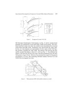
parallel and series. Notice that this system design requires
12
gate
valves,
2
check valves,
10
‘T’
connections, and
20
elbows. Because of
the high Hf in the area
of
the pumps, the actual head and flow
characteristics may be
less
than
the
theoretical characteristics. It appears
as in Figure
8-30.
The
same previously mentioned critical tips apply, plus one more. Upon
observing the system curve, with the pump curves,
it
appears that the
operator can operate any one pump, or any
two,
or any three or four
pumps. Actually there is no option
to
run three pumps in this
The
System
Curve
arrangement. Any three pumps, by the system design, indicate that
you’ll
be
operating
two
pumps on one side of the system and one pump
on the other side. The third pump will not
be
able
to
open the check
valve with
two
pumps keeping
it
closed.
So
in practice, you can operate
any one pump, or any
two
pumps (with the aforementioned hints from
the parallel operation section), or four pumps, but not three pumps.
The curve, shown in Figure
8-3
1,
is indicative
of
this operation.
Shaft
Deflect
ion
Introduction
Along with the sounds, evidence and signs of cavitation, there is
a
broad range of other information and signals available
to
the
maintenance mechanic. Almost all mechanics have seen the gouge and
scratch marks, and signs of heat on the pump when disassembled in the
shop. Sadly, most mechanics are never trained
to
interpret these marks.
This brings us
to
failure analysis of the pump, or performing an autopsy
on a broken pump. You must stop throwing away used and worn pump
parts, or sending them
to
the machine shop. This action destroys the
evidence needed
to
repair and resolve pump problems. There are
too
many mechanics wasting their careers changing parts and not really
repairing anything.
Let's begin with a discussion and explanation on how a volute
centrifugal pump works.
60"
and
240"
The volute type pump has its impeller mounted eccentrically within the
volute. The degree of eccentricity governs the pressure that the pump
can generate. If the impeller were concentric inside the volute, or
equidistant, the pump would generate flow, but not much pressure or
head (Figure
9-1).
The impeller throws the liquid against the volute wall
at
a constant
speed, the speed of the electric motor. The internal diameter of the
volute wall converts the velocity into head or pressure (Figure
9-2).
See
Table opposite for what is happening inside the pump around the
internal volute wall.
Shaft
Deflection
Distance
X
e
Y
-
Impeller mounted excentrical in the volute
Figure
9-1
-
C
G
__
D E
HARMONY AROUNDTHE VOLUTE CHANNEL
Figure
9-2
-
AT POINT PRESSURE
VELOCITY
AREA
A LO
w
HIGH
LITTLE
B
HIGHER
LOWER
MORE
C HIGHER
LOWER
MORE
D
HIGHER
LOWER
MORE
E
HIGHER
LOWER
MORE
F
HIGHER
LOWER
MORE
G HIGHER
LOWER
MORE
H THE MOST PRESSURE THE LEAST VELOCITY
THE MOST AREA
129
Know and Understand Centrifugal Pumps
Presssures are Equal.
-
~~~
Figure
9-3
With the pump running
at
its Best Efficiency Point, and all valves in the
system open, the factors of pressure, velocity, and area
are
in harmony
at
all points around the volute. All radial loads are in equilibrium
(Figure
9-3)
If a discharge valve should be throttled (increasing the resistance head,
Hf),
the pressure gradients around the volute would tend
to
equalize
toward discharge pressure. In
a
worst-case scenario, if a valve should
close completely, the pressures around the volute would become
discharge pressure. The pump would move
to
the left of its BEP on the
curve. The velocity would become zero because no fluid is moving
through the pump. The only remaining variable is the area, which is
greater through the E-F-G-H arc of the volute circle (Figure
94).
P=
V=
to the
left
of
the
The
Area
is
greater
in the
E-F-G-H-
arc
of
the
volute circle.
Zero
velocity
130
-
Shaft
Deflection
With pressures equal and more area in the E-F-G-H arc
of
the volute
circle, a tremendous radial force is created that will distort and deflect
the shaft toward a point approximately
60"
around the volute from the
cutwater. This radial force can destroy the mechanical seal or packing
rings, bearings, and deform and even break the shaft. The evidence
would be rub or scratch marks around the circumferences of close
tolerance rotary elements, such as the outer diameter on open or semi
open impellers
(see
Point
A
in the next illustration, Figure
9-5),
the
wear rings on closed impellers
(see
Point
B,
next illustration),
the
shaft
or sleeve at the restriction bushing in the bottom of the seal chamber or
stuffing box (see Point
C),
or on the posterior
of
the mechanical seal
(Point
D).
The scratch marks on the circumference of these close tolerance rotary
parts will correspond to scratch marks on close tolerance stationary
parts at approximately
60"
around the volute from the cutwater. These
marks will be visible on the back plate with open impellers, or on the
wear rings of pumps with enclosed impellers, or the
ID
bore of the
restriction bushing
at
the
bottom of the seal chamber where the shaft
passes through, or the
ID
of
the seal chamber bore at the back end of
the
mechanical seal (Figure
9-6
and Figure
9-7,
next page).
B-
A
h
/
A
-
Impeller
OD
B -Wear Band
C
-
Restriction Bushing
D
-
Seal
Posterior
Figure
9-5
~~~
STRICT TOLERANCE
~
_~_
Know and Understand Centrifugal Pumps
180"
270"
240"
~~
Figure
9-6
~.
~-
~ ~
__
Figure
9-7
The other case is when there is
too
much flow through the pump. The
pump is operating
to
the right
of
the
BEP on its curve (Figure
9-8).
The same problem occurs, but now in
the
other direction. With the
severe increase in velocity through
the
pump,
the
pressures fall
dramatically in the E-F-G-H arc of the volute circle (Bernoulli's Law
says
that as velocity
goes
up, pressure comes down). Now the shaft
deflects, or even breaks in the opposite direction
at approximately
240"
around the volute from the cutwater.
Shaft
Deflection
with high velocity there
IS
a
low
pressure zone in
the
E-F-G-H-
are
of
the
P
=
Low
pressure
V
=
High
velocity
Figure
9-8
Depending on the pumps available in your manufacturing or process
plant, you will experience:
Broken Shafts.
rn
Premature Bearing Failure.
Premature Mechanical Seal Failure.
Premature Packing Failure.
rn
Worn and Damaged Shaft Sleeves.
High Maintenance Costs on your Pumps.
You
can’t begin
to
resolve problems in your centrihgal pumps,
bearings and mechanical seals, until you learn the numbers
60°,
and
240°,
with respect
to
your pump cutwater.
~ ~~~
Operation, design and maintenance
~ ~~~
Once again, when the pump is operating at its
BEP,
all forces within the
volute (velocity, pressure, and the area exposed
to
velocity and pressure)
are in equilibrium and harmony. The only load on the bearings is the
weight of the shaft. The pump, the mechanical seal, and the bearings
will run for years without problems. When problems arise that cause
high maintenance costs with the pump (remember that seals and
bearings are the principal reason that pumps
go
into the shop) these
problems normally originate from one of three sources:
Know and Understand Centrifugal Pumps
H
Problems induced by Operations.
Problems induced by Design.
H
Problems induced by Maintenance.
Let's analyze the evidence that pump mechanics have seen
so
many
times. Consider the difference between a deflected shaft and
a
bent
shaft.
A
bent shaft is physically bent and distorted. Placing the shaft into
a
lathe
or
dynamic balancer and rotating
it
will reveal the distortion. If a
bent shaft is installed into a aupp and run, it will fail prematurely,
leaving evidence and specific signs on the circumference of close
tolerance stationary parts around the pump's volute circle. The shaft
will exhibit a wear spot on its surface where the close tolerance parts
were rubbing.
A
deflected shaft is absolutely straight when rotated in a lathe or
dynamic balancer. The deflection is the result of a problem induced
either by operation or system design. The deflected shaft also will fail
prematurely in the pump, leaving similar, but different evidence on the
close tolerance rubbing parts in the pump. The next
two
pictures show
how a bent shaft appears when rotated
180
degrees (Figure
9-9
and
Figure
9-1
0).
The basic difference between a bent shaft and a deflected shaft is the
following.
A
bent shaft spinning inside close tolerances leaves a scratch
mark around the circumference of stationary elements corresponding
to
a damaged spot on the shaft.
A
deflected shaft spinning within close
n
___~
Figure
9-9
U
Figure
9-10
134
Shaft
Deflection
n
LJ
LJ
Fiqure
9-11
Fiqure
9-12
tolerances leaves a scratch or gouged circle around the rotary element,
and a gouged or damaged spot on the stationary elements.
It
is
absolutely necessary
to
distinguish and recognize these significant
differences.
If the pump is put into service with
a
bent or unbalanced shaft
assembly, its premature failure can be traced
to
inadequate maintenance
practices. The evidence does not lie. However, if the premature failure
leaves evidence of a deflected shaft, this would be an operations or
design failure. All
too
often, the mechanic is blamed. The
two
pictures
above show how a deflected shaft appears when rotated
180
degrees
(Figure
9-11
and Figure
9-12).
Shaft deflection is the result of an external radial load. The external
radial loading originates with the pump operator or process when the
pump runs away from its best efficiency point on the curve. The
resistance
to
deflection is a function of the shaft’s overhang length and
its diameter. The deflection resistance, also called the flexibility factor, is
known as the L/D factor.
The L/D indicates length/diameter. Because pumps are manufactured
with certain dimensional standards (ANSI, API, DIN, and ISO), the
L/D factor can and should be specified
at
the moment of specifying the
pump. The design engineer could request that
the
pump manufacturer
quote a pump based on its flow, head, metallurgy, and L/D factor,
awarding bonus points for
a
low
L/D,
indicating a high deflection
resistance. The high deflection resistance is an index of how far the
pump can be run away from its
BEP
on
the curve without damaging
the mechanical seal and bearings.
1
__
135
Know and Understand Centrifugal Pumps
Rarely
do
design engineers request the
L/D
factor in their quotes.
Some engineers don’t know they have the option. Most pumps are
bought based on price, and because a high deflection resistance (low
L/D
Factor) indicates a larger diameter shaft with oversized bearings;
these type pumps don’t normally win a competitive bid process.
If
you suspect, or know, that you have a deflected shaft, or know that
standard operating procedure in your plant requires controlling the
flow in the pipes by opening and closing valves, then you have three
options
to
reduce shaft deflection:
Use
a
larger diameter shaft.
rn
Use
a shorter shaft (this may affect
the
motor mounts, and/or
piping mounts).
rn
Change the shaft metallurgy (this will change the elasticity modulus
and may even start a round of galvanic corrosion).
Increasing the shaft diameter is the most logical solution. This can be
done with some pump models by simply replacing sleeved shafts with
solid shafts, or by increasing the diameter of the solid shaft with
a
small
modification
to
the seal chamber bore. With the pump disassembled on
the shop table, the mechanic can identifjr the source of the problem in
the pump.
Signs
of shaft deflection
~~
Most pumps have tight tolerances in the following rotary elements:
rn
The
OD
of the blades on open and semi open impellers.
rn
The wear bands on pumps with enclosed impellers.
rn
The shaft under the restriction bushing at the bottom of the
stuffing box or seal chamber.
rn
The
OD
of the posterior end
of
the internally mounted mechanical
seal.
These tight tolerance rotary elements have corresponding tight
tolerance stationary elements. These are:
rn
The internal volute wall and/or back plate on pumps with open and
semi open impellers.
Stationary wear band bores on enclosed impellers.
The restriction bore at the bottom
of
the stuffing box or seal
chamber where the shaft passes through.
rn
Shaft
Deflection
The seal chamber internal bore corresponding
to
the posterior of
the mechanical seal
OD.
Interpreting the evidence
~
Let's interpret the physical evidence that you might
see
at these close
tolerances and their source.
To
begin:
1.
You might
see
gouge or wear marks all around the circumferences
of close tolerances on the rotary elements, and a corresponding
wear spot
at
approximately
60"
from the cutwater on the stationary
elements.
This would
be
induced or caused by operation, if the plant
operators strangle valves
to
control production flow. Any other
discharge flow restriction (clogged filter, pipe obstruction, or
un-calibrated automatic valve) would produce the same
evidence. Talk with the plant engineer about this situation and
show him the evidence on the pump.
This could also
be
induced
by
design, if the pumps are
oversized, or by high velocity and friction head in discharge
piping of inferior diameter.
This could be induced or caused
by
maintenance in cases where
the mechanic installs a check valve in reverse,
or
uses inadequate
practices when rebuilding valves, cutting and placing flange ring
gaskets at pipe joints, or exchanging and replacing incorrect
valves. Our recommendation is
to
always use good maintenance
practices.
L
I
Of
the three sources
of
problems, design, operation and maintenance, the mechanic
is
really responsible
for
a small part. The truth is that the majority
of
pump problems
begin with changes to design, and plant operations after the system
was
commissioned.
If the condition should be occasional, the solution could
be
to
install a variable speed motor. If the condition is permanent, the
solution could be
to
reduce the impeller diameter, replace the
pump, or increase the diameter of the pipe. If normal operations
require living with the condition, then increase the diameter of the
pump shaft
to
improve the
L/D
factor.
Know and Understand Centrifugal Pumps
2.
You
may
see
the same evidence all around the circumference of the
close tolerance rotary elements, with
gouge
or wear spots on the
stationary elements
at
about
240"
from the pump cutwater.
These marks are caused or induced by operations or by design.
This evidence is revealed when operating the pump
too
far to
the right of the
BEP
on its curve. Perhaps the pump is
inadequate and doesn't meet the flow and head requirements of
the system. It could also be that there is a loss of resistance in
the discharge piping.
A
big hole in
the
discharge piping could
present the same evidence.
If you must live with this condition, you need
to
increase the
diameter of the shaft
to
improve the
L/D
factor and deflection
resistance.
3.
If you
see
the same evidence,
gouge
and wear marks around the
circumference
of
close tolerance rotary elements, and spots or arcs
on the close tolerance stationary elements at about
180"
from the
cutwater, or straight down:
This would be a problem induced by inadequate design, caused
by pipe strain probably in a high temperature (thermal
expansion) application. The volute of the pump and the
stationary elements are growing up from the floor due
to
thermal expansion, against the rotary elements.
You
need
to
speak with the plant engineer and show him the evidence.
A
possible solution is
to
change your ANSI standard pump for
a
'High Temperature' or API design in this application.
See
the following graphs, Figure
9-1
3,
depicting thermal expansion.
The picture on the left shows an ANSI pump where thermal growth is
straight up from the base. On the right we
see
a high temperature
pump where thermal growth occurs
360
degrees around the volute.
Shaft
Deflection
The coefficient of thermal expansion of
316
stainless steel is
9.7
x
10-6
in/in per degree Fahrenheit. The metric equivalent is
17.5
x
10-6
mm/mm. per degree Centigrade.
See
the next Table and note the
expansion on a pump whose centerline is
10
inch above its base.
ATEMPERATURE ATEMPERATURE THERMAL EXPANSION
F"
c"
Inches Millimeters
100
"F
55
"C
0.0097 0.245
200
"F
110
"C
0.01 90 0.490
300
"F
165
"C
0.0291 0.735
400
"F
220
"C
0.0388 0.900
500
"F
275
"C
0.0485 1.230
600
"F
330
"C
0.0582 1.470
As
you can
see,
the pump casing will grow against its shaft almost
0.030
inches with an increase of 300°F. There are many tolerances in a pump
that are tighter than
0.030
inches. This means a rotary element will
scrape and rub a stationary element.
You
may even
see
the same evidence of
gouges
and wear around the
circumference of strict tolerance rotary elements, leaving a corres-
ponding spot on the stationary elements
at
any other point around the
volute circle of the pump.
This condition is probably misalignment, indicating a maintenance
problem. The mechanic should be trained
to
correct this. Follow
correct alignment procedures, as well as correct bolt torque procedures.
Inspect gasket surfaces for knots and irregularities.
Look
for bent dowel
pins and misaligned jack bolts, dirt and any other factor that might lead
to
misalignment.
Next we'll discuss evidence marks and prints that arc different, but
to
the untrained eye, they may appear the same.
You
may
see
a spot or arc
of
wear and gouging on the rotary elements, and a circumferential wear
circle on the bore of the close tolerance stationary elements. This is a
maintenance-induced problem. This is the sign of
a
physically bent
shaft, or a shaft that is not round, or a dynamic imbalance in the shaft-
sleeve-impeller assembly. The solution is
to
put the shaft on
a
lathe or
dynamic balancer, verify its condition, and correct before the next
installation.
The next condition and physical evidence we'll mention is rare, but
we
need
to
cover
it
in case you should ever
see
it.
You
might
see
scratch
and
gouge
marks all around the circumference of strict tolerance rotary
element
ODs,
and stationary element bores alike. This condition and
marks is evidence of a
'Lack
of
Control'.
It could be from any of the
139
Know and Understand Centrifugal Pumps
aforementioned reasons up
to
this moment, and even including
vibration, damaged and misapplied bearings.
The problem could
be
maintenance, operation, or design, or
a
combination of any or all these factors. In all honesty, you should never
see
this set of evidence marks because it indicates a lack of control. Now
because the mechanic cannot control operational problems or design
problems, the first phase
to
correct this situation is
to
control the
mechanical maintenance factors, like alignment, proper bolting and
torque sequences, be sure shafts are straight and round, and
dynamically balance all rotary components. Reinstall the pump and wait
for the next failure. Once the maintenance factors are under control,
there should appear a clear vision and path
to
resolve any operational
and/or design weaknesses.
The
sweet
zone
Consider the following graph, Figure
9-14.
Radial loading on the shaft
rises if the pump is operated
too
far
to
the left
or
right of the best
efficiency zone. Another interpretation of the same concept is
to
say
that the maintenance and problems rise when
the
pump is operated
away from its
BEP.
Many pumps have a rather narrow operational
window. These pumps can be very efficient if they are correctly
specified and operated. This is discussed completely in Chapters
7
and
8
Pump Curves and System Curves.
B.E.P.
FLOW
I
GPM
-
Figure
9-14
Shaft
Deflection
~-
The
dual
volute
pump
~
Some pump manufacturers use a different tactic
to
expand the
operating window of their products. This is why the dual volute pump
exists. The dual volute pump is designed
to
operate over
a
wide range
of
flows and heads.
In the casting procedure of the dual volute pump, a second cutwater is
designed
180"
opposite the first cutwater and another volute channel
added. This way, all areas exposed
to
velocity and pressure around the
volute casing are equal.
All
forces around the volute are equalized or
cancelled (Figure
9-15).
The second cutwater and volute channel create an additional
obstruction
to
the flow through this pump, and for that reason it robs
some energy from the fluid. This
will
reduce the efficiency
to
a small
degree, but the operational range of these pumps is quite broad as you
can
see
in the graph. The dual volute design casing is an optional cost
accessory with
some
pump companies, and offered standard with
others.
100%
Radial loading
IS
highest at
shut
-
on
head
1
001
0
50
100
150
Yo
Design
capacity
DUAL VOLUTE PUMP DESIGN
Figure
9-1
5
F-
141
Pump and Motor
Alignment
___
-
I
n trod
uction
Pump shaft and driver shaft alignment is very important for long useful
equipment life, and
to
extend
the
running time between repairs.
Besides, good alignment reduces
the
progressive degradation of the
pump.
I
Why do we use the word driver? We tend to think that pumps are powered by electric
motors. However, some pumps are powered by internal combustion engines, or with
turbines or hydraulic motors. Not always are pumps and drivers connected with a
direct coupling. Some pumps are coupled through pulleys, chain drives, gearboxes or
even transmissions.
If the pump shaft and impeller assembly were perfectly balanced and
aligned,
it
would rotate in
a
perfect orbit around the shaft centerline.
This condition is practically impossible. There is always some imbalance
in the shaft and impeller assembly due
to
its casting and machining
process, and perfect alignment doesn’t exist. Because of this, the shaft
spins eccentrically around
the
centerline.
We
could call this movement
‘eccentric rotation’. The implications of a pump exhibiting rotary
assembly imbalance (eccentric rotation) include:
Excessive running noise.
Vibration and excessive loads on
the
bearings causing premature
failure.
Rapid wear
of
the
coupling and eventual premature failure.
Premature packing or mechanical seal failure.
142
Pump and Motor Alignment
Wear and rubbing between close tolerance rotary and stationary
elements in the pump leading
to
their failure.
Premature driver bearing failure.
Increased energy consumption.
One of the most important and least considered points of correct
alignment is the relationship with the power transmitted from the
motor
to
the pump.
An
almost perfect alignment
(0.003
inch) with an
adequate and new coupling transmits almost
100%
of the motor’s
power (there will always
be
some small losses). The Pump performance
curve identifies the
BHP
or brake horsepower required for the pump
to
perform at its duty point.
The next graph (Figure
10-1)
indicates the expected continuous
running time of rotating equipment with increasing misalignment.
As
you soon
see,
the alignment improves and
so
does
the service time.
Excessive operating temperatures and lubricant failure.
1000.0
z
0
100.0
F
n
0
0
10.0
2
W
U
v)
I
I-
z
0
I
0
3
5
1.0
E
Z
0
0
0.1
Fiaure
10-1
ROTATING MACHlN ERY FA1 LU RE TIM
E
DUE TO MISALIGNMENT
0.002
0.050
0.050
0.100
TOTAL MISALIGNMENT
IN
INCHES
I
-
143