Know and Understand Centrifugal Pumps Episode 13 ppsx
Bạn đang xem bản rút gọn của tài liệu. Xem và tải ngay bản đầy đủ của tài liệu tại đây (507.41 KB, 20 trang )
Know and Understand Centrifugal Pumps
ir"
U
Ficlure
14-24
Install the pump back plate and seal chamber assembly. Mount the dial
indicator on the shaft and place the needle onto the outer diameter
of
the lip or face
of
the seal chamber (Figure
14-24).
An
alternate method
would be
to
place the indicator needle inside the seal chamber bore.
Rotate the shaft. This will verify that the shaft is concentric with the seal
chamber bore. If
it
is not concentric, the seal may rub against the bore
when the pump is started.
With the indicator still in this same position, place the needle onto the
lip or face
of
the seal chamber (Figure
14-25).
Rotate the shaft. This
Fiaure
14-25
224
Failure Analysis
of
Mechanical Seals
will verify the perpendicularity of the seal chamber
to
the shaft. If the
chamber is not perpendicular
to
the shaft,
the
seal’s faces and springs
will have
to
flex
twice with every revolution
to
maintain contact. This
will lead
to
fretting corrosion, a damaged pump shaft or sleeve, and
rapid failure of the seal.
225
Common Sense
Fa
i
I
u
re An
a
I
ys
i
s
h
Pump maintenance files
In most places, the available information about any pump, such as the
manufacturer, year of purchase, model and serial number is placed in a
file for general accounting purposes. In other plants, such as a
manufacturer, the model, lubricant and lubrication frequency is placed
in a lubrication schedule. In either case, additional key information can
be stored with a little more effort.
The complete maintenance record of a pump, when filed in an
accessible available place, is a valuable tool for diagnosing problems,
ordering parts for repair, and establishing lubrication and maintenance
schedules.
Also,
these maintenance files are valuable in determining the
performance
of
the pump during process changes. The comments on
the work orders, such as the list of materials or parts used, can define a
good
preventive frequency, a predictive and/or a planned maintenance
repair. Equipment records with good information can help extend the
period of inspection or identify specific checkpoints. In other pumps,
the records can indicate frequent failures. These they can be classified as
failures due
to
materials (incorrect parts), installation, maintenance
and/or operation. Good and precise information in the record of the
pump encourages applying a Root-Cause-Failure Analysis method. The
result of this analysis can suggest more inspections and repairs as well as
changes in operation procedures, frequency of lubrication or better
inspection procedures from project inspectors when accepting
a
new
installation. Organizing the data in chronological format is useful
to
diagnose problems, visualize what happened before
it
broke down and
who carried out the repair. Keeping simple and complete maintenance
records of each pump is more economical than trying
to
solve problems
without information using the method of trial and error.
With an appropriate record of repairs, you can use this information
to
226
Common Sense Failure Analysis
develop a correct parts inventory that is based on actual parts
consumption and not on recommended parts provided by the
manufacturer. The frequent replacement of worn parts can indicate
a
possible substitution of materials from the original OEM part.
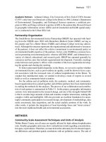
Record keeping is critical in those industries whose production requires
the
use
of many pumps. The record of the pump should have the
complete information on the installation, application and maintenance.
Space should be provided in each card, using both sides,
to
keep a
complete record during a two-year period, and in some cases, for the
whole life of the pump.
Failure analysis on centrifugal pumps
~~
Many times, the broken part of a pump is replaced when
it
fails without
an effort
to
understand why the situation happened. Any corrective
action that takes place is usually a temporary arrangement. The
probability is quite high that the pump will fail again for the same
reason. This part replacement with no analysis practice is not acceptable
due
to
the high cost of the maintenance, parts, time and lost
production.
It is interesting
to
note that some pump users literally know that their
pumps will fail after
a
specific time period. They understand that the
running time of the pump should be maximized
to
have an acceptable
yield in the process. This type of strategy is expensive since
it
raises a
doubt of the continuity of the pump performance.
To
compensate,
some plants install back up or redundant pumps.
In order
to
solve a pump failure, we have
to
identify the cause. Once
this is known, the problem can be dealt with and a permanent solution
can be found. A logical thought process (common sense)
to
identify the
problem is as follows:
1.
Ask ‘What’s making this happen?’
-
It is likely that what
we
call the
problem is actually the symptom. Example: ‘Low discharge
pressure’, ‘failed mechanical seal’, ‘the pump makes noise.’
2.
Look for the evidence
-
The evidence is the manifestation of the
symptoms. The evidence indicates that there is a problem with the
pumping system. Example: ‘the discharge gauges indicate
a
low
pressure’.
3.
Verify evidence
-
Example: ‘Is the gauge calibrated and accurate?’
Eliminate or cancel other reasons
or
possibilities for the evidence.
Example: ‘The pump is not pumping enough pressure and we’re no
longer able
to
fill
that tank.’
227
Know and Understand Centrifugal Pumps
4.
Identify the causes supporting the evidence. Example: What could
cause low pressure? The cause is the origin of the failure.
The causes of low pressure, for example, could be either hydraulic
or
mechanical. In many cases of failure analysis, asking ‘Why?’ and ‘What?’
and answering those questions, until you can
no
longer ask ‘why’, will
almost always get you
to
the answer.
If all evidence leads
to
a
mechanical reason for the failure,
the
problem is probably maintenance
induced. If the evidence leads
to
a hydraulic reason for the failure, the
problem is either operations
or
design induced. In cases where the
‘reason for failure’ was not determined, a more extensive analysis is
necessary. The additional analysis
is
recommended
to
take advantage of
the pump supplier experience in identifying the root cause.
ped properly. The pump axial
t
)ration.
It
was replaced with ai
so
failed. All pump component
~
A paper mill was using an ANSI en
The motor was desig
three months of ope
three months and al
they complied with the specificatioi
as a cause.
All the failed parts in the unit were
according to specifications. This ste
The maintenance team, that is to sa
followed the correct maintenance p
by maintenance.
Although the pump was being run
designed for this type of service.
outside
of
the Sweet Zone.
There remains only one cause to er
was contacted and their design grolrp
stuoIcu
tf1C
>IWdLIUII.
DV
UUCIIIIIU
UdtdllCC
IIUIC~
on the face of the impeller, they
manufacturer also incorporated a
flin!
to cool the oil and improved the oi
failure of the pump since !the redesigned pump was
ir
It
4
reduced the heat generated by
70°F.
The
jer ring lubrication system, a bigger oil reservoir
I
circulation. The plant has not experienced a
ed pump was installed.
d suction process pump with clear water service.
,hrust bearing ran hot, failing after
i
identical bearing. This ran during
s
were investigated and found that
ns.
These facts eliminated the defects
of
materials
inspected to assure that they were manufactured
p eliminated defects from the factory.
~y,
the mechanics, were found competent and they
rocedures. This information eliminates the defects
at
25%
of the
BEP
(Best Efficiency Point),
it
was
This eliminated improper operation or running
:plore, the design of the pump. The manufacturer
a A:-A
&I
-:& A:
D
_
:
L-t
-_
L-t
Why
is
this pump
in
the shop?
Did you ever notice that the building or area in the plant called the
‘maintenance shop’, is actually the Pump Hospital? The shop may have
twelve workbenches, but ten benches have a pump in some stage
of
surgery. You
go
into the shop and ask someone ‘Why is this pump in
228
Common Sense Failure Analysis
the shop?’ And someone says, ‘Because it was making noise’, or ‘The
seal failed’.
The noise and the
seal
failure are actually symptoms and not the
problem. This is like the electrician blaming the
fuse
for an overloaded
electrical circuit. The problem is the overloaded circuit and the
symptom is the burned
fuse.
Likewise, in the maintenance shop, the
noisy pump, the failed seals and bearings are the ‘Symptom’ of a
problem that probably occurred outside the pump.
In this book, we’ve dedicated whole chapters
to
seals and bearings.
However, there are some other complaints (symptoms) that send
pumps into the shop.
We
have listed below some of those reasons.
We
present them in table form with the symptom and the possible
hydraulic and/or mechanical cause for the symptom.
We
hope this
helps someone.
SYMPTOMS
AND
POSSIBLE ROOT-CAUSES
Symptom
Possible Hydraulic Cause Possible Mechanical
Cause
Noisy Pump.
Not enough discharge
flow
No discharge pressure.
Pressure Surge.
Inadequate Pressure.
Excessive Power
Consumption
Cavitation
Aspirated Air
Excessive Suction Lift
Not enough NPSHa
Excessive discharge Head
Not enough NPSHa
Pump improperly primed.
Inadequate Speed.
Not enough NPSHa.
Not enough NPSHa.
Not enough velocity.
Air or gases in pumped
liquid.
Head too small, excess flow.
High specific gravity or high
viscosity.
Bent Shaft
Bound Rotor
Worn Bearings
Worn or damaged impeller
Inadequate foot valve size.
Air aspiration or air pocket
in the suction line.
Plugged impeller or piping
Plugged impeller or piping.
Incorrect rotation.
Closed discharge valve
Air aspirated or air pockets
at the suction line.
Air aspirated or air pockets
at the suction line.
Entrained Air.
Plugged impeller.
Impeller diameter too small
Worn or damaged impeller
Incorrect rotation
Bent shaft.
Bound shaft.
Incorrect rotation.
229
Know and Understand Centrifugal Pumps
Although about half of all pumps manufactured in the world are
centrifugal (the other half are positive displacement), industry tends
to
use a higher quantity of centrifugal pumps. For that reason, much of
this book has dealt with pump theory, applications, and problems, from
a centrifugal point of view.
You
may think that we have abandoned
PD
pumps in this book.
You
would
be
wrong.
Actually, everything we said about bearings, mechanical seals, piping,
TDH,
system curves and mating the pump curve
to
the system curve,
the affinity laws, cavitation, horsepower and efficiency are as applicable
to
PD
pumps as centrifugal pumps.
So
in this chapter of failure analysis and corrective methods, we decided
to
consider some problems, symptoms, and remedies particular
to
I’D
pumps. We’re using
two
tables. The first table lists the few symptoms
that send a
I’D
pump into the shop. These symptoms are mated
to
another column of possible causes listed in numerical order. The
numerical causes are on the second table starting with the source of the
problem in the left column and the probable cause/suggested remedy
in the right column.
As
you
go
through the list, you’ll
see
again that
PD pumps and centrifugal pumps have a
lot
in common. Enjoy.
SYMPTOMS AND CAUSES
OF
FAILURE FOR POSITIVE DISPLACEMENT PUMPS
Symptom Possible Cause
Pump fails to discharge liquid.
Noisy pump. 6,10,11
,I
6,17,18,19
Pump wears rapidly. 11,12,13,16,20,23
Pump not up to capacity.
Pump starts, then loses suction.
Pump consumes excessive power. 14,16,17,20
1,2,3,4,5,6,8,9
3,5,6,7,9,21,22
1,2,6,7,10
Source
of
Problem Suggested CauselRemedy
1. Suction problem.
2. Suction problem
3. Suction problem.
4.
Suction problem.
5. Suction problem.
6. Suction problem.
7. Suction problem.
Not properly primed
Suction pipe not submerged
Clogged strainer
Foot valve leaks
Suction lift too high
Air leak in suction piping
Suction piping too small
Common Sense Failure Analysis
Source
of
Problem Suggested CauselRemedy
8.
9.
IO.
11.
12.
13.
14.
15.
16.
17.
18.
19.
20.
21.
22.
23.
System problem.
System problem.
System problem.
System problem.
System problem.
System problem.
System problem.
System problem.
Mechanical problems.
Mechanical problems.
Mechanical problems.
Mechanical problems.
Mechanical problems.
Mechanical problems.
Mechanical problems.
Mechanical problems.
Wrong rotation
Low
speed
Insufficient liquid supply
Excessive discharge pressu relresista nce
Grit or dirt in liquid.
Pump running dry
Viscosity of liquid being pumped is higher
than specified.
Obstruction in the discharge line
Unbalanced
or
misaligned coupling.
Bent motor shaft
Chattering relief valve
Pipe strain distorting the pump casing.
Air aspiration thru the packing/seal.
Inadequate relief valve.
Packing is too tight.
Corrosion.
I
Oh
yes,
'Comm
on
Sense
Maintenance' is likely to be the title
of
our
next book.
231
Pumps
Introduction
Avo
i
d
i
n
g
We
a
r
in
Centrifugal
In the moment of starting a new pump, that pump is headed for the
day when
it
will need repair even if the design and operation is correct.
One factor that determines the repair is internal wear. Imagine an ideal
application where the pump is operating at its BEP and the system is
stable.
Does
this condition ever exit? If you answer yes, you are one
of
fortunate few. However
at
some point, even if
it
does not break, the
pump
will
go
to
the shop because of internal wear. This chapter
presents different sources of internal wear and suggestions
to
extend
the useful running time of the pump.
Erosion
Erosion is the wear of the pump internal parts by suspended solid
particles contained in the fluid being pumped. The most affected parts
are: wear rings, shaft sleeves, packing, mechanical seal faces, lip seals,
the pump casing and the impeller.
Erosion can be caused by small particles not visible
to
the human eye,
like dissolved minerals in ‘hard water.’ Larger solids like sand, boiler
scale, and rust can also cause serious erosion inside the pump.
The fluid being pumped is often not well defined. Terminology like
well water, industrial effluent, raw water, boiler feed water, condensate
water, etc., is usually the only definition we have of the fluid being
pumped.
Any
of these fluids can contain several concentrations of solids
that cause erosion and wear inside the pump.
When the liquid being pumped is known
to
have a large concentration
of
solids, the materials inside the pump should be changed
to
more
Avoiding Wear in Centrifugal Pumps
resistant materials. Materials such as carbon steel, high chrome iron,
harden stainless steel or hard coatings
like
ceramic or tungsten alloy are
some of the most used.
Corrosion
Corrosion is caused by a chemical or electrochemical attack on the
surface of the metals.
It
is increased when there is an increase in
temperature and/or presence of oxygen in the fluid or the surface of
the fluid.
We can aggravate the corrosion effect if misaligned parts have relative
movement, such as loose
fit
bearings or rapid changes in
the
system.
Cavitation, erosion and high fluid velocity advance the corrosion
process.
Cast Iron is
a
widely used material for centrifugal pump housings. It is
used when the fluid
PH
is
6
or higher (not acid). Cast Iron corrodes
and forms a protective coating on
the
surface of the metal. This
graphitized surface protects the metal fi-om further corrosion as long as
the coating is intact. High velocity fluids, cavitation, metal
to
metal
contact and erosion can affect this protective coating.
If corrosion exists, the pump-wet parts can be changed for other
materials such as stainless steel or composite material. Impellers can
be
replaced by bronze cast impellers or other materials.
Wear
rings
Wear rings provide for a close running, renewable clearance, which
reduces the amount of liquid leaking from
the
high pressure zones
to
the low pressure zones in the pump. They are commonly fitted in the
pump casing and on
the
impeller (Figure
16-1,
next page).
These wear rings are lubricated with the fluid being pumped.
Eventually they will wear. Tolerances open and more liquid passes from
the discharge end back
to
the suction end of the pump. The rate of
wear is a function of the pumped liquid’s lubricity.
When
the wear is
excessive, the pump suffers degradation in its performance. This is
particularly true with small pumps running at high speed. The strict
tolerance in the replaceable wear rings governs the efficiency of the
pump. When the pump
goes
to
the shop, these wear rings should be
changed.
You can expect the pump
to
loose
1.5
to
2%
efficiency points for each
one thousandths
(0.001
inch) wear in a wear ring beyond
the
original
Know and Understand Centrifugal Pumps
t
Tolerance
Impeller
Wear Ring
factory setting. This setting is based on the operating temperature of
the application. Let’s consider how much money the lost efficiency
costs.
We
will
use
some formulas from Chapter
5
in this book on useful
work and efficiency.
0.000189
x
GPM
x
TDH
x
$Kwh
x
sp.gr.
x
8,760
Eff.
Pump
x
Eff.
Motor
Cost per year
=
where:
0.000189
=
Conversion factor
GPM
=
Gallons per Minute
TDH
=
Total Dynamic Head
$Kwh
=
Cost per Kilowatt-hour
sp.gr.
=
Specific Gravity
8,760
=
Hours in a year
Eff.
Pump
=
Pump Efficiency
Eff.
Motor
=
Motor Efficiency
To
show cost increase, consider this newly installed pump in a properly
designed system.
We
have the following values:
GPM
=
2,000gpm
TDH
=
120ft.
$Kwh
=
$0.10
Eff.
Pump
=
77%
sp.gr.
=
1
(water)
Eff.
Motor
=
93%
The electricity cost
to
run this pump for a year is
$55,450.80.
Mer being in line for six months, this pump is disassembled and
it
is
noted that the tolerance in the wear bands has opened
0.004
inch from
234
Avoiding Wear in Centrifugal
Pumps
the original factory setting. This wear represents an
8%
decrease in
efficiency. Now the pump is
69%
efficient. Let’s do the math with all
other factors constant. This reduction in the efficiency represents an
annual electricity cost of
$61,845.60.
The additional electricity is six
thousand
three
hundred ninety four dollars and eighty cents. Four
thousandths wear
(0.004
inch) has cost us almost
$6,500.00
per year
for just one pump. Just
to
mention, a new wear ring may cost up
to
$60.00
plus the labor
to
change
it
(this will never add up
to
$6,500.00).
Effective and well planned maintenance can reduce the operating cost
of your pumps and other equipment as this example demonstrates.
With differential pressure gauges on
the
pump, an amp meter and flow
meter you can determine if strict tolerance parts are worn. This
indicates the need
to
take the pump into the shop for corrective
procedures. If you don’t do
it,
you are wasting your annual operating
budget.
As
we mentioned in Chapter
6,
the Wear Rings should be
called Efficiency Rings. Now you know why.
Fluid velocity accelerates wear
Small impellers with high motor speeds may produce the necessary
pump pressure. This type of combination produces high fluid velocities
that will wear pump parts much faster than desirable. This is in the
Affinity Laws. In addition the impeller suffers rapid wear due
to
high
tip velocities. When
a
pump is disassembled and excessive wear is found,
95%
of the time high velocity fluid is
to
blame.
Tu rbu
I
en ce
Uneven wear in parts is often due
to
turbulence. Bad piping designs or
poorly sized valves can cause turbulence and uneven wear in pumps.
Whenever possible, use straight pipe sections before and after the
pump. Uneven flow creates turbulent flow and excessive wear occurs.
It
is not recommended
to
place an elbow at the suction of any pump
(Figure
16-2,
next page). This will cause a turbulent flow into the
pump. If elbows are needed on both sides of the pump, you should use
long radius elbows with flow straighteners. You should have
10
pipes
diameters before the first elbow on the suction piping (Example: If the
pump has a
4
inch suction nozzle, you should respect
40
inch of
straight pipe before the first suction elbow.) Short radius elbows cause
vibrations and pressure imbalances that
to
lead
to
wear and
maintenance on the pump.
235
Know and Understand Centrifugal Pumps
SUCTION
BEARING
DOUBLE SUCTION
ATTHE
E
OF
THIS
PUMP
RESS
IN THE BEARINGS
AND WEAR RINGS
MOTOR
Fiaure
16-2
A
pipe size increaser can be used in the discharge piping. This will
reduce the fluid velocity and friction
losses.
An
isolation valve with
a
low loss characteristic such as
a
gate valve should be placed after the
increaser and check valve.
Th
rott
I
i
ng
A
centrifugal pump should never be operated continuously at or near
the shut off head. This normally happens when a tank or vessel is near
the maximum capacity and an operator or level sensor starts closing the
discharge valve while the pump is running. This is similar
to
activating
your car brakes while the gas pedal is
to
the metal. All this wasted
energy is transferred
to
the fluid being pumped. This type of operation
shortens the life of the pump and increases the downtime. This energy
is converted into heat and vibration raising the fluid temperature. Some
pump casings can dissipate the heat. Other casings contain heat
switches that
will
trip-out and 'shut off the pump.
An
intensive radial load is created when operating near the shut-off
head and the shaft deflects at about
60"
from the cut-water. This
concept is explained in Chapter
9
'Shaft Deflection'. The pump will be
noisy, will vibrate and maintenance on seals, bearings and shaft sleeves is
expected.
Pumps are usually over-designed. From the initial specification stages,
future needs are taken into consideration, maximum flow is overrated
and operating conditions are uncertain. Design engineers following a
Avoiding Wear in Centrifugal Pumps
PROCESS
PRESSURE
RELIEF VALVE
k
I
I
I
Figure
16-3
financial guide
to
lower future capital investment do this. With this in
mind, no wonder we have
to
extensively throttle the discharge in order
to
achieve our necessary flow rate.
Yes,
this saves future capital
investments, but creates present problems with the daily maintenance
budget. Excessive throttling of the discharge valve results in severe
punishment
to
the pump.
Consider Figure
16-3.
This pump is draining a tank and discharging
into the process stream. If a control valve should be strangled
to
a
certain predetermined pressure (resistance), the pressure relief valve
automatically opens and
the
excess discharge pressure recirculates back
to
the suction tank. The pump never knows that the discharge control
valve is throttled. If this situation exists in your plant or if the operators
regulate the flow by manipulating control valves, this will be the proper
design
to
extend the useful life of your pump.
237
Pump Piping
I
n trod uction
We all know that piping is integral
to
the pump system. Because
it
is
connected
to
the suction and discharge, the piping affects the health
and well being of the pump. Incorrect pipe installation prejudices the
pump’s
useful
life.
In this chapter, we present graphic information on inadequate and
correct piping arrangements.
Piping design to drain tanks and sumps
When draining a tank with
two
pumps, you should not use a
‘T’
with
two
connections.
The
dominant pump may asphyxiate the other pump.
Each pump needs its own supply pipe (Figure
17-1).
INCORRECT CORRECT
Figure
17-1
PUMP
FMp
PUMP
E
PUMP
238
Pump Piping
INCORRECT CORRECT
eMp
PUMPP
Fiaure
17-2
The in-flow pipe should not cause interference with the drain pipe
(Figure 17-2).
INCORRECT
Figure
17-3
CORRECT
Drain pipe design must respect proper submergence (Figure
17-3).
The submergence laws appear later in this chapter.
INCORRECT CORRECT
Figure
17-4
-
Use vortex breakers (Figure
174).
239
Know and Understand Centrifugal Pumps
INCORRECT CORRECT
\t7
PUMP
&
PUMP
Design the level indicators
to
respect
the
proper submergence (Figure
17-5).
BUIBBLES
Figure
17-6
Inadequate sump design leads
to
entrained air bubbles and turbulence.
This will damage the pump (Figure
17-6).
240
Pump Piping
-
n
Figure
17-7
A
submerged
PREFERRED
DISCHARGE
POSITION
BAFFLE
STOPS
BU~BLES
TURBULENCE
AND BUBBLES
in-flow pipe and tank baffles prevent turbulence and
bubbles frgm entering thhe suction piping (Figuk
17-7).
f
Figure
17-8
-
The suction bell reduces entrance losses and helps
to
prevent vortices.
If you
use
a basket strainer, the screen area should be four times the
area of the entrance pipe. Avoid tight mesh screens because they clog
quickly (Figure
17-8).
241
Know and Understand Centrifugal
Pumps
AIR ASPIRATES PUMP
THROUGHTHE DISCHARGE
SUCTION
-1
BY-PASS
\
PACKING
Figure
17-9
Avoid high speed suction flow (Figure 17-9). This causes air
entrainment.
Also,
a
high suction
lifi
produces the same effect.
I
I I
~~
Figure
17-10
These are the dimensions
to
respect for proper sump design (Figure
17-10).
The submergence laws are independent
of
the pumps NPSHr.
The submergence laws are presented later in this chapter.
242
Pump Piping
Finlire
17-11
This aspirated air vortex is the result
of
not respecting adequate
submergence (Figure
17-1
1).
The submergence laws follow.
The
Submergence
Laws
Fluid Velocity
in Suction Pipe
In Feet per Second.
16
12
8
4
0
Minumum Submergence in Feet
Figure
17-12
-
243