Cardiac Catheterization in Congenital Heart Disease: Pediatric and Adult - Part 3 pps
Bạn đang xem bản rút gọn của tài liệu. Xem và tải ngay bản đầy đủ của tài liệu tại đây (866.67 KB, 95 trang )
CHAPTER 5 Catheter manipulations
179
If none of these maneuvers facilitates entrance into
the right ventricle and after no more than two or three
attempts, the most reliable means of advancing a catheter
from the right atrium to the right ventricle is with the use
of a deflector wire as described in the next chapter
(Chapter 6). When there is a large dilated right atrium or
ventricle or when the catheter is relatively straight to
begin with, experienced operators often resort to one of
the deflector-wire techniques as the very first alternative
in order to accomplish an expedient entrance into the
right ventricle before attempting any “flailing” around in
a large right atrium.
Right ventricle to pulmonary artery
After maneuvering the 180° loop into the right ventricle,
the next step of turning the tip of the catheter cephalad
and maneuvering a catheter from the right ventricle into
the pulmonary artery is often a very significant challenge,
particularly when the tip of the catheter has become
straight or soft. Significant dilation of the right atrium
and/or the right ventricle also makes this maneuver
more difficult. Maneuvering into the pulmonary artery
is considerably more straightforward when the catheter
has retained some of the stiffness of its shaft and some
of the right-angle curve at its distal end.
When the catheter does enter the right ventricle, particu-
larly from the femoral approach and after rotating a 180°
loop from the right atrium into the ventricle, the tip of the
catheter is usually directed caudally and toward the apex
of the right ventricle (Figure 5.18a). This caudal curve can
usually be straightened somewhat and directed laterally
(patient’s left) and toward the septal wall of the ventricle
by withdrawing the catheter in small increments while
continuing small to-and-fro movements and small rota-
tions of the proximal shaft of the catheter (Figure 5.18b).
Clockwise torque is applied to the catheter while all of the
time using tiny, to-and-fro motions on the proximal shaft
of the catheter. The to-and-fro motions allow the shaft
of the catheter within the body to rotate freely and keep
the tip moving in and out of the many trabeculations in
the right ventricle, while the torquing rotates the curved
tip posteriorly along the septal wall of the right ventricle
(Figure 5.19, a and b). With the tendency of the catheter
to straighten and point cephalad, the continued torque
along with the to-and-fro motion “walks” a curved tip of a
catheter up the posterior, septal wall of the right ventricle,
over the crista and into the posteriorly directed pulmon-
ary artery (Figure 5.19c).
Occasionally, with a large and hypertrophied right vent-
ricle or in the presence of an inlet (atrioventricular canal)
type ventricular septal defect, the initial rotation of the
catheter needs to be counterclockwise instead of the usual
clockwise. In the presence of a very large crista, the tip of
Figure 5.17 Maneuver of loop from right atrium to right ventricle. Loop
directed medially with tip of catheter against tricuspid apparatus (position
a); careful slight withdrawal of proximal catheter allows loop to open
slightly and drop into the right ventricle (position b).
Figure 5.18 “Straightening” the 180° loop in RV. Position of tip of catheter
in RV after rotating 180° loop into ventricle (position a); straightening of
catheter across RV by withdrawing shaft of catheter (position b).
CHAPTER 5 Catheter manipulations
180
the catheter must first be rotated anteriorly and out from
under the crista with the counterclockwise rotations of the
shaft of the catheter. Once the tip of the catheter has
“popped” anteriorly and out from under the crista, the
catheter is advanced while the rotation of the catheter
shaft is simultaneously reversed to a clockwise direction.
This redirects the curved tip from facing anteriorly to
posteriorly and cephalad (and over the crista) toward
the pulmonary valve.
In the presence of a significant inlet ventricular septal
defect, there is no posterior wall of the right ventricular
septum. The usual clockwise rotation of the shaft of the
catheter turns the curved tip posteriorly in the right ven-
tricle and, as a consequence, directs the tip back through
the atrioventricular valve and usually directly into the
left atrium. In the presence of an inlet ventricular septal
defect, once the tip of the catheter has been advanced from
the right atrium into the right ventricle, the initial torque
on the shaft of the catheter along with the usual short to-
and-fro forward motions should be counterclockwise. This
maneuver will “walk” the curved tip anteriorly, over the
free wall trabeculations of the right ventricle, cephalad
and toward the patient’s left. Once the tip has advanced
as far as possible cephalad and laterally in the ventricle,
the torque on the catheter is reversed to clockwise along
with the continued to-and-fro motions, in order to redirect
the tip posteriorly, over the crista and toward the main
pulmonary artery.
When the right ventricle is very large or there is not a
good curve on the end of the catheter, then various wires
or deflector techniques (Chapter 6) are used to manipulate
the catheter from the right ventricle into the pulmonary
artery.
Utilizing purposeful loops on the catheter for
manipulations
With advanced skill and familiarity with specific cath-
eters, their feel and their characteristics, large loops formed
on the catheter can be used to the operator’s advant-
age for entering difficult locations. When loops are
formed, the operator must be sure that the shaft of the
catheter is free in the particular chamber and has room to bend
or loop within the particular cavity or large vessel when
forward force is applied to the proximal end of the catheter.
Otherwise, if the shaft of the catheter is constrained, the
forward force applied to make the bend or loop will be
directed only in line with, and to the tip of, the catheter
(and possibly through the heart or vessel wall!). Several
examples of the use of these back loops are detailed:
1 The use of a large 180° loop formed in the right atrium
to enter the right ventricle was described previously in
this chapter. Starting with the tip of the catheter against
the lateral wall of the atrium as described previously,
and with care taken that the catheter tip is against a free
wall and not burrowed into the right atrial appendage,
a loop is formed by advancing a soft catheter against the
resist-ance of the wall (Figure 5.15 a, b). Once the loop is
formed and using continual, fine, to-and-fro motions of
the catheter, the shaft of the catheter is torqued either
clockwise or counterclockwise until the whole loop of the
catheter rotates (Figure 5.16). The tip and the whole
loop of the catheter are observed intermittently in both
the PA and LAT fluoroscopic planes during the entire
rotation. As long as the tip remains free, the catheter
is rotated in small increments until the loop rotates 180°,
resulting in the distal curve of the catheter’s facing an-
teriorly and to the patient’s left, and usually, as a conse-
quence, the actual tip will be pointing away from the
tricuspid valve. Once the distal loop is directed toward
the valve, the loop tends to open and direct the distal
end and the tip toward the tricuspid valve, in which
case the catheter’s shaft is alternately advanced and
withdrawn slightly, which, in turn, pushes the tip caud-
ally and through the tricuspid valve and into the right
ventricle (Figure 5.17). Usually the tip of the catheter
continues caudally and anteriorly toward the apex of
the right ventricle. Once the tip has been secured in the
apex, the shaft of the catheter is withdrawn slowly until
the 180° curve in the shaft of the more proximal catheter
within the right atrium straightens gradually, while at
the same time still keeping the tip of the catheter within
the right ventricle (Figure 5.18). As the catheter straight-
ens and courses directly from the IVC to the right
Figure 5.19 “Walking” catheter from IVC up wall of RV. Catheter tip in
apex of RV (position a); catheter tip advanced cephalad along septal wall of
RV (position b); catheter tip rotated and advanced further cephalad into
right ventricular outflow tract (position c).
CHAPTER 5 Catheter manipulations
181
Figure 5.20 Use of 360° loop to enter right ventricle from right atrium
and inferior vena cava approach. (a) Forming laterally directed 360° loop in
right atrium; (b) advancing 360° loop into right ventricle; (c) continuing to
advance catheter into pulmonary artery using 360° loop in right atrium/right
ventricle.
ventricle, the tip becomes directed cephalad and more
toward the outflow tract (Figure 5.19).
2 A large 360° loop formed on the catheter in a very large
right atrium can be used to enter the right ventricle/
pulmonary artery. The tip of the catheter is maintained
pointing laterally in the right atrium (toward the patient’s
right) when forming the atrial loop. By continuing to
advance the catheter in the right atrium with this “laterally
CHAPTER 5 Catheter manipulations
182
directed” loop, the catheter eventually approaches a com-
plete 360° loop within the atrium. This loop, which began
heading toward the lateral wall of the right atrium, now
directs the distal end of the loop and the tip medially,
toward the patient’s left and roughly toward the tricuspid
valve (Figure 5.20a). With the proximal loop still directed
to the patient’s right in the atrium, the catheter shaft is
moved to and fro further and, if necessary, torqued
slightly, in which case the tip of the catheter becomes
directed toward the patient’s left, slightly anteriorly and
toward the tricuspid valve. Further simultaneous torque
and fine to-and-fro motion on the catheter direct the tip
across the tricuspid valve and into the right ventricle, now
with the curved tip directed cephalad (Figure 5.20b). By
advancing the catheter further, the tip advances directly
into the great artery which arises cephalad off the right
ventricle (Figure 5.20c).
3 Similarly, the coronary sinus is entered more easily
from the femoral approach with a loop formed on the
catheter in the right atrium similar to the 360° loop
which has just been described. With the tip directed later-
ally (to the patient’s right) and slightly anteriorly when
forming the right atrial loop, as the catheter is advanced
further in the right atrium, the catheter again completes
a 360° loop. However, by reversing the previous torque
on the catheter as it is advanced, the torque results in
the distal portion of the loop and the tip of the catheter
pointing posteriorly. When advanced further with very
slight torque and to-and-fro motions, the tip enters the
coronary sinus and is directed in the course of the coro-
nary sinus. Lateral fluoroscopy is extremely helpful
(essential) in accomplishing this maneuver. The 360°
loop is useful as a way of entering the coronary sinus, par-
ticularly for performing electrophysiologic procedures.
This entry into the coronary sinus may occur inadver-
tently during attempts at entering the right ventricle with
the 360° loop and should be considered when the distal
portion and the tip of the catheter are constrained in their
lateral movement.
4 When attempting to advance a catheter from the
femoral approach, even with the catheter passing straight
from the right atrium into the right ventricle and into the
pulmonary artery, entrance into the right pulmonary
artery is often difficult to negotiate, particularly when
the catheter has straightened and/or when there is a
large dilated right ventricle. The right pulmonary artery
has a more proximal take-off and is even more acutely
angled off a dilated or displaced main pulmonary artery.
With the tip of the catheter fixed against the wall in the
main pulmonary artery, the soft catheter can be care-
fully and continually advanced against the resistance of
the tip until a curve, and eventually a 360° back loop,
is formed on the more proximal shaft of the catheter,
which is still in the right atrium. This 360° loop on the
more proximal shaft of the catheter redirects the tip of the
catheter, which, hopefully, is still in the pulmonary artery,
toward the patient’s right and caudally. Further advanc-
ing the catheter with this 360° loop directs the tip from
the main pulmonary artery into the right pulmonary
artery. A 360° loop formed in the right atrium initially
as described above in (2) (Figure 5.20c) often produces
the same effect on the tip of the catheter after it enters
the main pulmonary artery, directing the tip slightly more
rightward and caudally and, in turn, directly into the right
pulmonary artery.
5 Although it is safer and more direct to use a preformed,
stiff end of a wire to deflect the tip of a catheter from
the atrium into the ventricle, occasionally it is desirable
to back a loop that is more proximal on the shaft of the
catheter, through the atrioventricular (AV) valve. In this
way, the tip of the catheter, which is following the more
proximal loop into the ventricle, will be facing the oppo-
site direction from the loop entering the ventricle. By
“backing” a narrow 180° loop at the distal end of the
catheter into the ventricle, the tip of the catheter “follows”
the loop into the ventricle and will be directed toward the
outflow tract and the semilunar valve. A loop can be
backed into either ventricle through either atrioventricu-
lar valve from the connected atrium using a relatively soft,
easily bendable catheter (any woven dacron catheter after
it has been in the body more than 15 minutes).
To create the initial loop in the left atrium, the tip of
the soft catheter is directed against the cephalad and
either right or left wall of the left atrium. The catheter
is slowly and carefully advanced against this fixed tip
of the catheter. This creates a slight loop or bow in the
catheter shaft just proximal to the tip and within the
left atrium. The loop usually forms caudally and toward
the AV valve. Further advance of the proximal end of
the catheter bows the catheter and pushes the loop
through the atrio-ventricular valve into the ventricle. It
is usually necessary to stiffen or support the apex of the
loop in the catheter with the stiff end of a spring guide
wire with a very slight and long curve formed on the
stiff end of the wire (see Chapter 6). As the loop that
is near the distal end of the catheter advances into the
ventricle, the tip follows the loop into the ventricle (with
or without the help of a stiff wire) but now with the tip
pointing “backward” or cephalad. Once in the ventricle,
the loop of the catheter is pushed toward the apex by
slight rotation of the catheter or loop while the tip is
still directed toward the outflow tract. As the catheter is
advanced further into the ventricle or is advanced off the
supporting wire, the tip advances away from the apex of
the loop and through the more cephalad semilunar valve
arising from the ventricle.
6 When the catheter is introduced from a superior vena
cava approach, a loop is often formed in the right atrium
CHAPTER 5 Catheter manipulations
183
in order to advance a catheter from the right atrium into
the right ventricle and, from there, into the pulmonary
artery. With a catheter introduced from the jugular, sub-
clavian or brachial vein, it usually passes directly from
the superior vena cava, through the tricuspid valve and
into the apex of the right ventricle (Figure 5.21). From
this position and when directed caudally toward the apex,
the tip of the catheter can seldom be manipulated toward
the right ventricular outflow tract and into the pulmonary
artery without significant or traumatic manipulations
or the use of deflector wires. This is particularly difficult
when the catheter has straightened or has become very
soft.
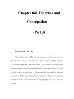
As an alternative, the tip of the catheter is initially
directed from the superior vena cava toward and against
the lateral wall of the right atrium. By further advancing
the catheter, a large 180+° loop is formed within the right
atrium until the tip of the catheter is pointing cephalad
(Figure 5.22a). By rotating the whole 180+° loop in the
catheter (Figure 5.22b), the tip of the catheter is rotated
in the right atrium from laterally to medially and toward
the tricuspid valve (Figure 5.22c). With this rotation, the
distal end of the loop and the tip of the catheter tend
to flop through the tricuspid valve, with the tip of the
catheter pointing directly at the right ventricular out-
flow tract/pulmonary artery (Figure 5.22d). Advancing
Figure 5.21 Catheter introduced via the superior vena cava passed directly
from the right atrium into the right ventricle and apex of the ventricle.
the catheter with minimal torque or manipulation pushes
the tip of the catheter into the main and usually the right
pulmonary arteries, usually without the use of deflectors
or other wires (Figure 5.22e).
7 Loops are occasionally made in the great arteries in
order to redirect the tip of the catheter 180° (or more) for
selective entrance into side branches, which arise at very
acute angles off the central vessel. Such loops are used for
entering the brachiocephalic branches off the aortic arch,
for entering collaterals off the descending aorta, and for
entering branch pulmonary arteries. Usually, for these
purposes, a 180+° loop is formed with an active deflector
wire within a very soft catheter as described in Chapter 6.
The loop is formed distal to the origin of the branch/side
vessel to be entered. Once the loop has been formed, the
catheter with the loop maintained in its distal end is
withdrawn within the central vessel until the “backward
facing” tip is drawn into the side vessel. Once the tip
catches in the orifice of the branch vessel, as the catheter is
withdrawn further, the tip of the catheter will advance at
least for a short distance into the side vessel.
8 Loops in the distal end of a catheter introduced from a
retrograde approach can be used to cross the semilunar
valve from the aorta. Occasionally, the tip of the retro-
grade catheter continually drops into the sinus of the
semilunar valve and, even without stenosis of the semi-
lunar valve, will not pass readily through the valve.
When the catheter has become very soft, often a loop
will form at the distal end of the catheter when the tip
is pushed into the sinus of the semilunar valve. Such
a loop will direct the tip of the catheter cephalad and
away from the semilunar valve. In that circumstance,
the valve orifice can be probed with the loop in the
catheter, which extends several centimeters in front of the
tip of the catheter. The apex of this loop now extends
across the lumen of the aorta, which centers the apex
of the loop across the center of the valve annulus, which,
in turn, allows the loop to pass through the central orifice
of the valve.
9 A loop that has passed retrograde through the semi-
lunar valve is very useful for purposefully crossing a
perimembranous and/or high muscular interventricular
septal defect and for entering and crossing the semilunar
valve arising from the ventricle on the opposite side of
the ventricular septal defect
2
. As a loop at the distal tip
of the catheter is backed through the semilunar valve into
the ventricle, the tip of the catheter tends to align trans-
versely across the outflow tract. By torquing the catheter
and, in turn, rotating the loop very slightly in the outflow
tract, the tip of the catheter will flop through the ventri-
cular septal defect while still tending to point somewhat
cephalad. When the catheter is advanced with the curve
at the distal end passing through, and resting on, the
lower margin of the ventricular septal defect, the tip is
Figure 5.22 Utilizing a 180° to 360° loop to enter the right ventricle
and pulmonary artery from the superior vena cava approach;
(a) Forming a loop against the lateral wall of the right atrium;
(b) rotating the 180+° loop in the right atrium; (c) 180+° loop directed
toward tricuspid valve after rotation; (d) loop advanced into right
ventricle and directed toward RVOT; (e) loop advanced into main
pulmonary artery.
CHAPTER 5 Catheter manipulations
185
directed further cephalad and into the semilunar valve
at the other side of the ventricular septal defect.
If the loop was not backed through the semilunar valve,
and in order to manipulate the tip of the catheter through
a ventricular septal defect and/or into the semilunar
valve on the opposite side of the defect, a loop or curve can
be formed at the tip of the catheter with an active deflector
wire while the tip of the catheter is in the outflow tract
of the ventricle just below the semilunar valve. This is
described in Chapter 6, “Guide and Deflector Wires”.
Non pressure monitored catheter manipulations
In exceptional occasions and in experienced hands, the
catheter can be disconnected from the proximal flush/
pressure line and capped with a syringe, while very
specific and complex maneuvers of the catheter are being
performed. This removes the additional resistance to
torque caused by the connecting tubing at the proximal
end of the catheter but, at the same time, removes the pro-
tection and reassurance of knowing exactly where the
catheter tip is located, which are provided by the moni-
tored and visualized pressure from the tip of the catheter.
This technique is most commonly utilized when manipu-
lating the tip of the catheter within large veins or great
arteries in order to cannulate side vessels very selectively.
It is the preferred technique for the selective cannulation
of the coronary arteries. This technique is used only when
the catheter is moving very freely within the sheath and
vascular system so that all movements and all sensations
of resistance are transmitted from the tip and the shaft
of the catheter to the fingers which are maneuvering the
catheter. The capping syringe on the proximal hub of the
catheter is filled with contrast material, which is used to
perform small injections of contrast periodically in order
to confirm the position of the tip of the catheter. Only very
experienced and skilled operators should attempt this
technique when it is utilized for manipulation within
cardiac chambers.
Since even more precise and difficult maneuvers of
the catheter can be accomplished using deflector wires
within the catheter, catheters are often detached from the
pressure/monitoring system when wires are used in the
catheter to deflect the tip. With most catheter/wire com-
binations, pressures can still be obtained simultaneously
while there is a wire in the catheter by introducing the
wire through a wire back-bleed valve with a flush port
and attaching the flush port to the pressure system. When
a tight, Tuohy™ type of valved/side port is used with a
Mullins™ deflector wire, very accurate pressures can be
recorded while the wire is in place in the catheter. The
techniques, advantages and dangers of the deflector wire
techniques are detailed in Chapter 6 on “Guide Wires and
Deflection Techniques”.
Preformed catheters
There are thousands of different catheters available, most
of which have very special, fixed, preformed curves at
their distal ends for the purpose of selectively cannulating
very specific vessels or orifices. Many of these catheters
are in the standard armamentarium of the adult catheter-
ization and the vascular radiology laboratories. These
catheters are extremely effective for the cannulation of
specific vessels and particularly in a usual sized patient
where the basic structures and anatomy are located
normally and predictably. Unfortunately, none of these
prerequisites apply very often in pediatric/congenital
heart patients. Preformed catheters are often useful in a
pediatric/congenital patient, but are usually used in an
entirely different location or for an entirely different pur-
pose than that for which the specific curve was designed
and manufactured.
Even preformed coronary catheters, which make can-
nulation of the coronary arteries in the adult patient an
almost automatic and unconscious procedure, are usually
not very useful for cannulation of the coronary arteries in
children and congenital patients. The different diameters
of the aortic root, the markedly different lengths from the
aortic sinuses to the aortic arch in younger patients, and
the frequent aortic arch and coronary artery anomalies in
congenital heart patients compared to the usual adult
coronary patient preclude the automatic use for even the
coronary arteries in pediatric/congenital patients.
These same selective “coronary curves”, however, are
often useful for the selective cannulation of branch vessels
off the descending aorta and off the main or the right or
left pulmonary arteries. A small “right coronary artery
curve” is very useful for directing a wire from the right
ventricle to the exact center or opening of an atretic/
stenotic pulmonary valve. Once an abnormal and difficult
course to an unusual location or a branch vessel is defined,
there is often a preformed catheter that can facilitate the
selective cannulation of that vessel/location with either
the catheter itself or with a wire passed through the
catheter. Unfortunately, it is impossible to maintain a
complete or even a very large inventory of very many of
these very specific catheters.
Complications of catheter manipulations
There are a very few complications that are a consequence
of the manipulation alone of standard catheters. Certainly,
direct perforation of a vascular and/or cardiac structure is a
common fear, but in actuality it is extremely unusual and
unlikely
3
. Most cardiac catheters that are manipulated
within the heart or vascular system are somewhat “soft”
and very flexible. As a consequence, when a catheter tip is
forced into or against a structure and/or wall, the catheter
CHAPTER 5 Catheter manipulations
186
shaft bends or bows to one side and dissipates any for-
ward push or force sideways and away from the tip.
The exception, when a catheter can be pushed through an
intracardiac or vascular structure, is when the shaft of the
catheter is confined or restrained within a vessel or chamber
or has already bowed sideways to the limits of the walls
within the chamber or vessel. In that circumstance, all
additional forward force on the catheter will be transmit-
ted longitudinally along the shaft of the catheter and
directly to the tip of the catheter, which, in turn, can force
the tip through a wall.
Perforation of a vessel by a catheter occurs most com-
monly in the peripheral venous system. In that area, the
shaft of the catheter is constrained very tightly by the lat-
eral walls of the small peripheral veins at the introductory
site and, at the same time, the veins themselves are very
thin walled, almost “friable”, they have many small tribu-
taries which arise tangentially, and the tributaries narrow
rapidly when they are any distance from the main chan-
nel. This combination of factors makes it easy to trap the
tip of a catheter in a branch/tributary and to deliver sig-
nificant forward force to the tip because of the side-to-side
restraint of the catheter within the small more central vein.
Other, more serious examples of vascular perforation
occur when the tip of a catheter is wedged into an atrial
appendage in conjunction with a 180–360° loop that has
been formed on the shaft of the catheter and already
extends around the widest circumference of the atrial
chamber, or when the tip of the catheter is buried in a
sinus of the aortic valve while the shaft of the catheter is
pushed tightly against the outer circumference of the aor-
tic arch. When additional force is applied to advance the
catheter forward in either of these circumstances, the shaft
of the catheter has no further lateral or side-to-side space
to bow away from the force. As a consequence, all of the
forward force is transmitted to the tip. These are rare cir-
cumstances which can be avoided by awareness of the
potential problem, careful observation of the entire course
of the catheter during all manipulations, and avoidance of
all significant force applied to the catheter during manipu-
lations. The management of cardiac wall perforations is
covered in detail in the chapters dealing with specific pro-
cedures where perforations are more likely (Chapter 8,
“Transseptal Technique” and Chapter 31, “Purposeful
Perforations”).
Probably the most common adverse event/complica-
tion of catheter manipulations is the creation of ectopic
beats or sustained arrhythmias. Isolated, or even short,
self-limited, runs of ectopic beats are a part of catheter
manipulations within the heart! Fortunately most pediatric/
congenital heart catheterizations, although in complex
defects, are carried out in younger patients who have nor-
mal coronaries and healthy myocardium. In these patients,
when ectopy does occur, it is not sustained nor does even
a sustained arrhythmia usually result in a deterioration of
the hemodynamics. When older or adult congenital heart
patients are catheterized, they do not necessarily have this
protection of underlying healthy myocardium and/or a
margin of safety in their hemodynamic balance and, as
a consequence, far mare attention must be paid to even
isolated ectopic beats in such patients. Occasionally, an
ectopic beat in a pediatric or congenital patient triggers
a sustained run of tachycardia and very, very rarely, even
fibrillation and/or heart block, any of which can cause
hemodynamic instability. This can occur in any patient
but is far more common in patients with myocardial dis-
ease, older patients, and patients with defects associated
with ventricular inversion.
When a catheter manipulation does result in multiple
ectopic beats, the manipulation is stopped and/or changed
to allow the heart rhythm to stabilize. The appropriate
medications and a defibrillator are always available. A
printed medication sheet, which has the exact dose of each
emergency medication pre-calculated in both milligrams
and milliliters for each individual patientaas described in
Chapter 2a certainly facilitates the rapid administration of
medications. The defibrillator is preset for each individual
patient at the onset of the procedure and is immediately
available close to the catheterization table for the conver-
sion of an arrhythmia.
Thrombi and/or air flushed from the catheter during
the manipulation of any catheter creates the potential for
catastrophic problems, but problems which should be
avoidable. In many congenital heart patients, “right heart”
catheterizations have the same potential for catastrophic
systemic embolic phenomena as “left heart” manipulations
because of the frequency of intracardiac communications
and/or discordances. As a consequence, all catheteriza-
tion procedures in pediatric/congenital heart patients are
considered “systemic”. Catheters are always allowed to
bleed back and/or blood is withdrawn with an absolutely
free flow before anything is introduced into and/or flushed
through a catheter and/or sheath. Wires are always intro-
duced into catheters through back-bleed valves with flush
ports, and catheters with wires in them are maintained on
a flush to keep thrombi from forming on the wire within
the catheter. Pediatric/congenital heart patients under-
going cardiac catheterizations should all be systemically
heparinized in order to reduce the likelihood of thrombi
formation in catheters and/or on wires. When catheters
are manipulated with guide or deflector wires within them,
the procedures do become potentially more hazardous.
The complications associated with wires are covered in
Chapter 6.
Catheters easily can become kinked and even knotted
unknowingly whenever loops or bends are formed in
them, particularly when they are not observed closely.
This occurs most commonly in the inferior vena cava
CHAPTER 5 Catheter manipulations
187
when a very soft catheter is being manipulated against a
curve and/or resistance within the heart and the inferior
vena cava is out of the field of visualization. Knots and/or
kinks occur most commonly with flow-directed balloon
tipped catheters and woven dacron torque-controlled
catheters, which become very soft in the warmth of the cir-
culation. The treatment of kinks and knots is prevention.
The catheterizing physician must always be aware of
the presence of and the position of the entire catheter. A
to-and-fro or rotational movement performed on the
proximal catheter outside of the body should always be
transmitted to a similar (identical!) movement at the tip of
the catheter and in a “one to one” relationship. If the prox-
imal end of the catheter is advanced 6 cm, the distal end
and tip of the catheter within the cardiac/vascular silhou-
ette should move forward a comparable 6 cm. When the
proximal shaft of the catheter is rotated properly, the tip
of the catheter within the heart/vasculature should rot-
ate proportionately. Whenever these “one to one” move-
ments of the proximal and distal ends of the catheter do
not occur, the entire length of the catheter/wire should be
visualized immediately.
A catheter with a “simple” kink or twist in its shaft usu-
ally can be straightened and/or withdrawn directly into
and through the introductory sheath. If the kink or twist
is the consequence of a prior 360° loop, the shaft of the
catheter on one side of the twist becomes offset from the
shaft at the other side of the twist, and cannot be with-
drawn through a sheath of the same size without first
“unwinding” the twist. “Unwinding” the kink or twist is
accomplished by re-advancing the catheter and rotating
the loop that has formed in the opposite direction to the ini-
tial twistaall very carefully and under direct vision. The
stiff end of a spring guide wire with a slight 30–45° curve
preformed at the stiff end is introduced into the twisted
catheter and advanced to the area of the twist/kink. This
curve on the wire is transferred to the shaft of the catheter
and usually helps to begin opening the loop and unwind-
ing the twist.
Usually, if a knot has not been tightened by totally
uncontrolled maneuvering, it can be untied by advancing a
spring guide wire into the catheter while simultaneously
advancing the catheter in the area of the kink/knot. Either
the soft end or a slightly curved stiff end of the wire, when
advanced adjacent to the knot, is often sufficient to change
the angle of the shaft of the catheter entering the knot
enough to allow the straight portion of the catheter imme-
diately adjacent to the knot to be pushed into, and loosen,
the knot enough to begin untying it. If the knot cannot
be loosened completely with the wire within the catheter
itself, a second sheath is introduced into a separate vein
and an end-hole catheter advanced to a position adjacent
to the knot. A 0.025″ tip deflector wire with a 1 cm curve at
the tip is advanced through the second catheter. With the
aid of biplane fluoroscopy, the tip of the wire is manipu-
lated into and through the loop in the knot. Once the tip of
the wire has advanced into the knot, the tip of the deflector
wire is deflected tightly. This grasps one edge of the loop
of the knot in the catheter, allowing the knot to be teased
apart by the combination of pushing on the wire that is
within the lumen of the knotted catheter while gently
pulling on the loop of the knot with the separate deflector
wire
4
.
A third alternative for “untying” knots that have
become very tight is to use a bioptome as the second
catheter instead of the deflector wire. When a wire cannot
be passed through a loop in the knot, one edge of the
catheter within the knot is grasped with the jaws of the
bioptome while pushing the knot apart with a stiff wire
within the lumen of the knotted catheter. If a knot cannot
be “untied”, a significantly larger sheath is introduced
into the second vein, the tip of the knotted catheter is
grasped with a snare introduced through the larger
sheath, and the knotted catheter is withdrawn into the
larger sheath. Once the whole knot is within the larger
sheath, the proximal end of the knotted catheter must be
amputated to allow it to be withdrawn into the venous
system and out through the larger sheath.
As with all complications, prevention is the best treat-
ment. With catheter manipulations in particular, the proper
handling and maneuvering of catheters can prevent most,
if not all, complications.
References
1. Gensini GG. Positive torque control cardiac catheters.
Circulation 1965; 32(6): 932–935.
2. Mullins CE et al. Retrograde technique for catheterization of
the pulmonary artery in transposition of the great arteries
with ventricular septal defect. Am J Cardiol 1972; 30(4):
385 –387.
3. Lurie PR and Grajo MZ. Accidental cardiac puncture during
right heart catheterization. Pediatrics 1962; 29: 283–294.
4. Dumesnil JG and Proulx G. A new nonsurgical technique for
untying tight knots in flow-directed balloon catheters. Am J
Cardiol 1984; 53(2): 395–396.
188
Introduction
There are numerous times when neither precise catheter
manipulation utilizing a torque-controlled catheter or
blood flow using a balloon flow-directed catheter will
direct the catheter to a specific location. Even when the
catheter starts with a preformed curve at the tip, the warm
body temperature within the circulation tends to soften
and, in turn, straighten the curves at the tip of many
catheters. The repeated “pushing” of a straight catheter
(“straight wire, catheter, anything”!!), even with a balloon
at the tip, only results in the linear object advancing in a
straight line. No matter how many pushes and rotations
are attempted the straight tip does not change its direc-
tion. There is frequently the need for the tip of the catheter
to “reverse” direction as much as, or even more than, 180°
in order to cross a valve or enter a branch or side vessel.
The importance of selectively entering stenotic, distal or
branching vessels is intensified by the added necessity of
securing extra stiff guide wires far distally in these vessels,
which has become imperative with the advent of balloon
dilation and intravascular stent implant in these lesions.
Fortunately, there is now a large variety of special wires
to assist in directing the catheter precisely to the specific
area, no matter how small and tortuous the course may be.
With these special adjunct wires and the specific tech-
niques for their use, there is little excuse for the statement
“can’t be entered” in the sophisticated biplane pediatric/
congenital catheterization laboratory of the twenty-first
century.
Back-bleed/flush devices for wires
All wires when used within a catheter should be used in
conjunction with a valved wire back-bleed valve/flush
device attached to the proximal end of the catheter in
order to prevent blood loss and to allow flushing to
prevent thrombosis around the wire. This is vitally import-
ant when the wires are to remain within the catheters for
any length of time. These back-bleed/flush devices not
only eliminate blood loss through the catheter and around
the wire, but allow continual or intermittent flushing
through the catheter. The flushing prevents thrombus
formation around the wire within the catheter
1
. This is
equally as important when the wire/catheter combination
is used in a low-pressure venous system as it is in a high-
pressure area (e.g. in a ventricle or great artery), where the
blood bleeding back into the catheter around the wire is
more forceful and more obvious. The continual flush also
lubricates wires within catheters, making any manipula-
tions of them smoother. This is important particularly
when using catheters manufactured of extruded plastic
materials, when using wires that have a tight tolerance
within any type of catheter, and when using any of the hy-
drophilic coated, “glide” type wires within any catheter.
By interruption of the continual flushing, intermittent
pressure monitoring can often be accomplished through
the side port, even with a wire within the catheter. Pres-
sure monitoring helps to identify the location of the tip
of the catheter when it is in an area that it is essential
or particularly difficult to enter. The back-bleed valve/
flush system also allows the capability of injecting small
amounts of contrast through the catheter around the wire.
This is extremely helpful for verification of the location
of the tip of the catheter during maneuvers where a wire
is being used in the catheter to assist the positioning of
the catheter. With the more sophisticated, rigid, “Y”-
connectors with Tuohy type of compression wire back-
bleed valves, pressure injections of contrast for angiograms
can be performed with the wire in place within the catheter.
A wire maintained within the catheter is very often essen-
tial to stiffen the catheter and to keep it in its exact position
during some high-flow pressure contrast injections.
There are several types of specific wire back-bleed/
flush devices, which are effective for controlling bleeding
while wires are passing through them. Unfortunately,
6
Special guide and deflector wires and
techniques for their use
CHAPTER 6 Guide and deflector wires
189
none of the catheter back-bleed valves that commonly are
available on the hubs of sheaths are effective at all at
preventing bleeding around wires passing through
them. The simplest wire back-bleed device is a rubber
or latex “injection” port with a “Y” or “T” side arm (Coris
Corp., Miami Lakes, FL). These rubber ports are com-
monly available in neonatal and intensive care units for
intravenous injections into existing lines. They were
designed to be used attached to the hub of intravenous
lines and used primarily for the repeated insertion of
needles through the rubber port for the purpose of injec-
tions of medications into the lines. At the same time, these
injection ports make very simple, inexpensive, yet very
effective wire back-bleed valve/flush ports to prevent
bleeding around wires and allow the flushing of catheters
that have wires within them. The simplest of these wire
back-bleed valve/flush ports has a straight slip-lock con-
nector with a proximal rubber valve and a side port of a
short length of connecting plastic tubing attached to the
side of the valve apparatus.
The wire back-bleed valve apparatus is attached to the
catheter hub, the wire is introduced through the rubber
port (initially usually through a needle, a wire introducer
or “Medicut” canula which has punctured through the
rubber valve) and the side arm is attached to the
flush/pressure system. This simple device effectively pre-
vents bleeding and allows intermittent pressure recording
alternating with the flushing of the catheter. These simple
rubber valves do not allow pressure injections of contrast
around the wire, and occasionally the pressure curves that
are transmitted through them are dampened.
A more effective, yet still simple type of back-bleed
device is a small “Y” Luer-Lok connector with a Tuohy™-
type compression grommet/valve on the straight arm
of the Y (Merit Medical Systems, Salt Lake City, UT; B.
Braun Medical Inc., Bethlehem, PA; and C.R. Bard, Inc.,
Covington, GA). This grommet is tightened around the
wire to produce a tight seal. This tight seal and the rigid
side arm permit very accurate pressure recordings, flush-
ing of the catheter, and, when maximally tightened, allow
a pressure injection through the side port with the wire
still in place in the catheter. A direct connection of the pres-
sure recording tubing to the female Luer-Lok connection
off the side of the Y allows more accurate pressure record-
ings as well as pressure injections through the side port.
Sophisticated (and expensive) variations of this Y type
of Tuohy™ valve with rotating Luer connectors have been
developed for coronary angiography and can be used
with any of the wire uses that will be described. All of the
Y–Tuohy™ systems can be used for pressure injections
during angiography while none of the non-Tuohy™
hemostasis devices are useful for pressure contrast injec-
tions. With all of these valve/side port devices, care is
taken that the side port and the valve “chamber” are flushed
free of any entrapped air before the valve/side port is
attached to the catheter and that the chamber within the
back-bleed valve/flush port is cleared of air and clot
before flushing through the valve to the patient. Negative
pressure never should be applied to, nor an attempt made
to withdraw blood through the side port of, a hemostasis
valve of any type when it is attached to the catheter and
there is a wire passing through the valve of the back-bleed
device. When any suction is attempted through the side
port of a back-bleed valve through which a wire is pass-
ing, air is preferentially drawn in through the valve around
the wire along with any blood that is being withdrawn
through the catheter.
In the absence of a commercially available Y or T wire
back-bleed device, and in order to prevent massive blood
loss during the use of a wire within a large catheter or
sheath that is positioned in a high-pressure system, a very
simple, makeshift back-bleed device can be improvised.
The latex plug taken off an injection port of an intravenous
(IV) fluid bag can be used to produce an effective back-
bleed plug. The valve from the IV bag is removed from the
bag while it is still sterile, when the covering package of
the IV fluid bag is first opened. When the fluid bag is not
opened on the sterile field, a latex plug from another bag
can be used. If the bag is not maintained sterile when
opened, the latex plug must be removed from the bag and
sterilized separately in a gas sterilization system and
saved in a sterile package in anticipation of such a use.
The latex plug fits into the female Luer™ hub and folds
securely over the rim of the hub of the catheter. The rim or
edge of the plug is rolled over the lip of the catheter hub to
create a tight seal. The plug allows the introduction of the
wire through it and effectively prevents bleeding around
the wire.
This make-shift hemostasis plug, however, does not
allow flushing nor continuous pressure monitoring and,
consequently, is not recommended for routine use. Since
it does not allow flushing of the catheter, the plug should
be used only for short periods of time, the wire should
be removed every few minutes, and the catheter cleared
and flushed repeatedly
2
. The large dead space within the
catheter and around the wire when the catheter is not on a
flush can, and usually does, result in a large thrombus
developing in this space within a short period of time. On
removal of the wire when using this or any other plug or
back-bleed valve, the system is cleared carefully of air and
clots by a thorough withdrawal of blood directly from the
hub of the catheter before the catheter is flushed.
Heparin
Because of their “rough” invaginated surfaces, all spring
guide wires have the potential to be quite thrombogenic
CHAPTER 6 Guide and deflector wires
190
within the circulation. Some spring guide wires have
some type of “heparin coating” or binding, which report-
edly reduces (but does not eliminate) their thrombogenic-
ity. Teflon coatings, which reduce the “stickiness” of wires
within catheters, possibly enhance thrombogenicity
1
. The
original recommendations for the use of guide wires in the
circulation were that they should never be left in a catheter
and/or within the circulation for more than several min-
utes without withdrawing the wire and cleaning it and
also clearing and flushing the catheter every several min-
utes! In the era of complex and very long interventional
procedures, which are often performed over hours and
require “supporting” spring guide wires during the entire
procedure, this recommendation is certainly not reason-
able and the notion on which it is based has been dis-
proved clinically, if not scientifically. At the same time
thrombi do occur on intravascular guide wires and all
possible measures should be used to eliminate the forma-
tion of thrombi and embolic phenomena from wires.
Always introducing and using wires through back-
bleed valves with flush ports and maintaining the lumen
of any catheter that contains a wire on a “continual” flush
with a heparinized flush solution appears to be sufficient
to prevent thrombi from forming around wires within the
catheter. Not leaving the wire “bare” in the circulation
any longer than necessary by keeping a wire completely
within the catheter and on the continual flush whenever
possible (e.g. when not actually maneuvering the wire
ahead of the catheter or after positioning a wire for a bal-
loon dilation with a guide catheter, but while preparing
the balloon and before introducing the balloon) will
reduce the “free wire” time in the circulation. Finally, all
patients in whom guide, support or deflector wires are
used (all patients?) should receive 100 units/kg of intra-
venous heparin prior to any maneuvers in the circulation
with wires.
Standard spring guide wires
Spring guide wires, as their name implies, are tubular
spring wires made of an extremely uniform winding of
a very fine, usually stainless steel wire. The winding
of wire is hollow and the lumen within this tubular wind-
ing of wire contains at least one length of very fine flexible
ribbon wire, which is welded at both ends of the tubular
winding and serves as a safety wire to prevent the wind-
ings of the wire from pulling apart. Many spring guide
wires have an additional, stiffening or core wire, which
also runs most of the length within the outer winding of
the wire. At the distal end of the tubular wire the stiffer,
central core wire is usually 1–10 cm shorter than the wound
wire, or the central wire tapers to a very fine, flexible wire
for that distance at the distal end. In either case, the core
wire adds stiffness to the length of the wound spring
guide wire except at the distal tip, where it either is absent
or tapers, which results in its remaining very flexible or
even floppy.
Spring guide wires are available in an almost infinite
combination of diameters, lengths, stiffness, tip configura-
tions and coatings. The wires that are packaged with per-
cutaneous introduction sets are usually 45–80 cm in
length while most wires for use within catheters or the
exchange of catheters are between 150 and 400 cm in
length. There are wires as small as 0.014″ and as large as
0.045″ and each diameter comes in various degrees of stiff-
ness. Most of the spring guide wires will support the pas-
sage of catheters through tortuous courses within the
vascular system, at least to some degree. The flexible dis-
tal ends of the wires vary in length from 1 to 10 cm and, in
addition, vary from slightly flexible to very soft and flex-
ible. Some spring guide wires are coated with teflon or
with heparin with the intent of increasing lubricity within
polyurethane catheters and decreasing thrombogenicity,
respectively
1
.
Spring guide wires, including those with special
modifications, are probably the most commonly used
expendable items in the catheterization laboratory. Spring
guide wires are used for the percutaneous introduc-
tion of all sheaths/dilators and catheters. They are used
extensively for the selective cannulation of side or branch
vessels as well as for crossing valves during both pro-
grade and retrograde approaches. Spring guide wires
are now used to support diagnostic catheters during com-
plex manipulations, to support the delivery of therapeutic
sheaths/dilators, and to support all varieties of balloon
dilation catheters during dilation procedures.
Standard spring guide wires have been used in the
catheterization of pediatric and congenital heart patients
for over three decades. The wires are used for routine
catheterization procedures as well as for entering loca-
tions where the usual or standard catheter manipulations
are unsuccessful
2
. Guide wires are advanced out of the
tip of the catheter and into a desired location, after which
the wire is advanced over the catheter into the chamber/
vessel. Wires of various sizes with straight soft tips,
curved tips or J tips are advanced out of the tips of either
straight or curved, end-hole catheters and then the wires
are directed selectively into specific areas or orifices. Once
the wire is secured distally in the area or orifice, the
catheter is advanced over the wire into the area
2
.
This use of spring guide wires is particularly useful
when, after some time within the body, the catheter
becomes soft, and even though the catheter is pointing
directly at the desired location it forms back loops rather
than advancing when forward motion is applied to the
CHAPTER 6 Guide and deflector wires
191
proximal catheter. In this circumstance, a standard spring
guide wire with a soft or J tip is introduced through a wire
back-bleed valve/flush port into the catheter and ad-
vanced through the catheter and, from the distal end of
the catheter, the tip of the wire is advanced beyond the
catheter tip and quite easily into the desired opening.
Occasionally some curve at the distal end of the wire is
helpful in directing the wire, but usually when using stand-
ard spring guide wires, the direction of the wire toward an
orifice is accomplished by changing the location/direc-
tion of the tip of a slightly curved catheter.
Whenever a wire is advanced out of the distal tip of a
catheter, only very soft, flexible tipped and/or J tipped wires
should be used. The shaft of the catheter always must be
free and able to move away (back) from the direction of the
tip as a wire is extruded from the tip of a catheter. If the tip
of the catheter is confined within the walls of a vessel or in
a small chamber and the shaft of the catheter is constrained
in the vessel/chamber so that the catheter cannot move
freely and the tip of the catheter cannot move readily
away from a wall or surface, the wire will be forced
through the wall of the vessel/chamber as it is extruded!
(Figure 6.1a). If, on the other hand, the catheter is not con-
strained and is free to move from side to side in the vessel,
the tip of the wire that is pushing against the vessel/
chamber wall will push the tip of the catheter away and
allow the wire to deflect (Figure 6.1b).
Often the additional stiffness provided to the shaft of a
very soft catheter by a wire within its lumen is sufficient to
allow the otherwise soft, non-maneuverable catheter to be
maneuvered forward purposefully. A short segment of an
exposed soft tip of the wire, which is beyond the tip of the
catheter, can also add some directional control to the tip,
while the presence of the stiffer portion of the wire within
the shaft of the catheter allows more of the torque applied
to the proximal end of the catheter to be transmitted to the
distal end and tip of the catheter. This alone often facilit-
ates the manipulation of the catheter tip into the desired
location or to be advanced off the wire into the desired
location.
Torque wires
Materials
A torque wire is a special guide wire that has a very rigid
core wire, which provides a “one to one” (or very close to
“one to one”), rotation or “torque ratio” between the prox-
imal end and the distal tip of the wire. Torque wires all
have very floppy distal tips of various lengths beyond
their stiff shaft. Torque wires either are spring guide wires
with the special core wire or are manufactured of a fine,
uniform Nitinol™ metal shaft with a softened tip. Both
Figure 6.1 (a) Catheter constrained within walls of vesselAwire pushing into and through vessel wall when advanced out of catheter; Perf., site of
perforation. (b) When catheter is not constrained within walls of vessel, it can push away from the wall as wire is advanced.
CHAPTER 6 Guide and deflector wires
192
types of torque wire are available in various diameters
and lengths with a relatively stiff shaft and a long, floppy
distal end and tip. The entire floppy portion of these wires
is often made of a different material that is extra dense
when visualized on fluoroscopy. These extra dense tips
allow better visualization of the specific maneuvers of the
tip as a result of torquing. The floppy distal segments of
spring guide torque wires are initially straight and usu-
ally 5–10 centimeters in length, but can vary in length
from a few centimeters to 15 cm. A slight curve must be
formed on the distal tip of a wire before its use as a torque
wire, in order that any torque or rotation applied to the
proximal straight shaft of the wire has “an angle to turn”
at the tip of the wire.
The connection or “transition” portion between the stiff
shaft of the spring wire and the floppy distal portion is
usually quite abrupt. This abrupt change in stiffness along
the wire creates a significant problem with most of these
torque wires. While the curved, floppy portion of the wire
can almost always be maneuvered into virtually any
desired opening or orifice (Figure 6.2a), the stiff portion of
the wire proximal to the transition area often will not fol-
low the floppy segment through angles or bends that are
at all acute. As the stiffer shaft of a torque or other guide
wire that has had the soft tip successfully positioned in a
side branch, is advanced further toward the orifice of a
side branch, and as the transition area of the wire reaches
the orifice, unless this “following” stiff portion of the wire
is aligned exactly with (parallel to) the distal softer portion
of the wire, the transition and stiff portions of the wire
usually will not follow the floppy portion of the wire into
the orifice (Figure 6.2b). Usually the stiff portion of the
wire continues in a straight direction, which withdraws
the previously positioned floppy portion out of the area or
vessel (Figure 6.2c).
The wires are supplied with small, finger comfortable,
vice-like devices which clamp on the proximal portion
of the wire to facilitate the torquing of the wire. The 1:1
torque characteristics of these wires allow a curved tip
of the wires to be directed in very specific directions by
fine precise rotation (torquing) along with simultaneous,
short to-and-fro motions of the proximal wire. As during
the maneuvering of all catheters or wires through long
channels (vessels, sheaths or catheters), in addition to the
torque applied to the proximal end of the wire, the wire
must be kept in this constant, slight, to-and-fro motion.
There are many torque wires available. Those most
frequently used in pediatric and congenital patients are
the Wholey™ wires (Advanced Cardiovascular Systems
[ACS], Santa Clara, CA), the Platinum Plus™ and Magic™
wires (Boston Scientific, Natick, MA), the Ultra-Select™
and HyTek™ wires (ev3, Plymouth, MN)) and the Nitinol
Glide™ wires (Terumo Medical Corp., Somerset, NJ and
Boston Scientific, Natick, MA).
Figure 6.2 (a) Soft wire advanced out of tip of catheter into perpendicular side branch/orifice; (b) “transition” or stiff portion of wire does not follow soft tip
of wire into orifice of a side branch when the wire is not advanced directly in the direction of the side branch; (c) curved catheter continues to advance along
the wall of the vessel and pulls the soft wire out of the side branch when an attempt is made to advance a stiff curve in the catheter over the soft portion of the
wire entering a side branch/orifice.
CHAPTER 6 Guide and deflector wires
193
Technique using torque wires
All torque wires must have at least a slight curve on the
distal, soft tip in order to have something to “turn” when
the proximal wire is rotated. Rotating a perfectly straight
object (or wire) does not alter the direction of a straight tip
at all. Torque wires are maneuvered with the soft end
of the wire advanced out of and well beyond the tip of an
end-hole catheter. The wire is then manipulated with its
floppy tip totally exposed in a cardiac chamber or vessel.
As with other wires used through catheters, it is essential
to introduce the torque wire through a wire back-bleed
valved/flush device. With the tip of the wire still within
the tip of the catheter, the tip of the catheter is maneuvered
to a position as close as possible to, and pointing in the
direction of, the desired orifice or side branch vessel
before the wire is advanced out of the catheter. The tip of
the catheter should never be forced against or into the wall
of the vessel or chamber as the wire is being advanced out
of it, as even the soft tip of a torque wire can perforate
a wall when the catheter is constrained in the vessel/
chamber (Figure 6.1a).
The tip of the wire is advanced out of (beyond) the tip
of the catheter and selectively manipulated into the
desired side branch or orifice by turning (“torquing”) the
proximal end of the wire while simultaneously adjusting
the position of the tip of the catheter toward the orifice
and rotating and moving the wire slightly to and fro.
Maneuvering a torque wire is like maneuvering a torque
catheter, using fine, short, to and fro, but fairly rapid
motions of the wire as it is turned simultaneously within
the catheter. Torquing the wire without the to-and-fro
motion is likely to have no effect on the tip of the wire ini-
tially and then suddenly, several rotations of the previ-
ously applied torque will be transmitted to the tip of the
wire all at once resulting in a propeller-like rapid rotation
of the tip of the wire rather than a precise, controlled turn-
ing of the tip.
Torque wires are very effective for entering side
branches of vessels that arise at an oblique, and not too
acute, angle off the main vessel. The floppy portion of these
wires can almost always be manipulated into the side ves-
sel regardless of the angle of its take-off (Figure 6.2a),
however, the stiffer, supporting portion of the wire often
will not follow if the angle off the main vessel is at all
acute. As much of the distal, soft segment of the wire as is
possible (all of it!) is advanced into the side or branching
vessel before an attempt is made to advance the catheter
over the wire. In order to have all of the soft end of the
wire in the branch vessel, the distal end of the soft portion
of the wire must often be doubled back on itself or actually
wadded up in the side or branch vessel in order to have
the stiff portion approach even near the side orifice. Often,
as the transition or stiff portion of the wire approaches the
take-off of the branch vessel, the straight, stiff portion does
not make the bend to angle into the side vessel. Instead,
the following, more proximal, stiff portion of the wire con-
tinues in a straight direction on past the orifice. As a conse-
quence, instead of the stiff portion of the wire entering
the side vessel, the floppy portion of the wire is pulled
backward or actually flips out of the side branch. A small,
preformed curve on the transition portion of the wire
between the floppy and straight stiff wire assists in the
passage of the stiffer portion around the angle; unfortun-
ately, even a small curve on the stiffer, transition, portion
of the wire will compromise the free rotation of the wire
severely when torquing it within a catheter is attempted.
A standard end-hole catheter will usually not follow
over the soft distal portion of the wire even when it will
readily follow over the stiffer portion of the same wire.
When an attempt is made to advance the catheter over
only the soft portion of the wire, the catheter continues in
a forward direction along the vessel and will pull the wire
out of the side branch/orifice (Figure 6.2c). For this rea-
son, when these wires are used to advance a catheter over
the wire into a specific location, a significant length of the
stiff portion of the guide wire that is proximal to the
floppy tip must be advanced well within the branch vessel
before an attempt is made at passing the catheter over the
wire. With this one, often very frustrating, exception,
these wires are very effective at selectively catheterizing
very small orifices which arise at moderate angles away
from the main direction of the catheter. Torque wires are
also excellent for traversing very circuitous courses
through chambers and vessels.
Once the tip of the torque wire is through the orifice of a
side or branch vessel, the wire is advanced cautiously
until the stiff portion follows the tip and is deep into
the side branch. This often requires several different
approaches to the vessel and may require that a long
floppy portion of a wire be bunched or balled up in the
distal vessel. Once the stiff portion of the wire has been
advanced at least some distance into the side/branch ves-
sel, the catheter is advanced as far as possible over the
wire into the side/branch vessel. Once the catheter has
been advanced over the wire to the desired distal vessel
location, the original torque wire is removed, leaving the
catheter in place in the vessel. With this initial catheter
securely in place, then a larger and stiffer wire can be
introduced through the catheter in order to guide larger
delivery catheters or sheaths into the area for complex
interventional procedures.
With all of the torque wires, care must be taken to avoid
permanent bends, kinks or even permanent smooth
curves on any part of the stiff shaft of the wire. Even a
small acute bend or kink on the shaft of the wire causes
CHAPTER 6 Guide and deflector wires
194
that portion of the wire to conform to the curves of the
catheter within chambers or vessels through which the
catheter is passing, and prevent any purposeful rotation
of the tip of the wire (Figure 6.3). If the wire inadvertently
develops a bend or kink and further torquing or manipu-
lation is required, the wire should be exchanged for a
new one without wasting time and fluoroscopy exposure
trying to torque the bent wire.
Terumo™ “Glide wires”
Terumo™ “Glide wires” (Terumo Medical Corp., Somerset,
NJ) are not spring guide wires but hydrophilic coated,
solid Nitinol™ wires which functions as guide wires. The
Glide™ wires are available in four sizes (0.025″, 0.032″,
0.035″ & 0.038″), in multiple lengths including exchange
lengths, and in standard and extra stiff versions. The
Glide™ wires all have a short soft(er) tip at one end and
are available with a straight or very slight curve on this
soft tip. The Nitinol™ material is almost impervious to
additional bending, forming or kinking and retains or
returns to its straight configuration even after extensive
bending or buckling within the heart or vessels. The solid
wire construction of the Terumo™ wires gives them an
ideal, 1:1 torque ratio. The Nitinol™ is coated with a
hydrophilic material that makes the wires extremely
slippery as long as the surface of the Glide™ wires is kept wet.
These two characteristics give these wires the unique
property of passing (“gliding”) through very small
orifices and often through very tortuous courses through
the heart and great vessels. These wires follow particu-
larly well when they are advanced in the direction of
blood flow and along the course of an existing channel.
The Glide™ wires must be kept very wet at all times.
When the wires begin to dry at all, they become very
sticky and bind within catheters, particularly in catheters
made of extruded plastic. This binding within a catheter is
particularly severe when the internal diameter of the
catheter is close to the outside diameter of the wire.
Although generally considered safe and freely maneu-
verable within vessels and chambers, these wires
definitely have the ability to perforate myocardium and
even vessel walls easily when the tip of the wire is
advanced out of the tip of a catheter that is confined
(restricted in its lateral movement) within a vessel or
chamber and the tip of the catheter is wedged against, or
into, the wall of the chamber or vessel. Because of their
“gliding” and smooth characteristics, there may be little or
no unusual sensation of force as these wires pass through
vessel walls, tissues and/or myocardial walls!
Techniques for the manipulation of Terumo™
Glide™ wires
It is imperative that the Terumo™ wire is prepared by
thoroughly flushing the entire length of the housing of the
wire with saline or dextrose/saline flush solution in order
to wet the entire wire while it is still within the tubular
housing. The Glide™ Wire is introduced directly from
its housing into the catheter as it is withdrawn out of the
housing. The wire is introduced through a wire back-
bleed valve/flush port on the catheter, which is main-
tained on continual flush. Terumo Glide™ wires are all
manipulated beyond the tip of the catheter. The tip of the
end-hole guiding catheter is maneuvered to a location in
the vicinity and direction of the desired opening or orifice
that is to be entered, but at the same time, the tip of the
catheter is not forced tightly against any structure or surface.
The Terumo™ wire is advanced gently beyond the tip
of the end-hole catheter and the wire, which is free in the
circulation, is maneuvered to the desired location.
The Terumo™ wire is maneuvered beyond of the tip of
the catheter with gentle, repeated probing with the wire
as the catheter and wire are torqued and maneuvered
to and fro so that, eventually, the changing directions
of the combination will direct the tip of the wire toward
the desired orifice. The manipulation of the Glide™ wire
is similar to the manipulation of any other torque wire,
i.e. frequent gentle, to-and-fro probes while rotating the
wire or catheter. With each to-and-fro advance of the
wire, the proximal end of a curved tip, Terumo™ wire
is rotated with a torque control device attached pro-
ximally on the wire outside of the catheter. In addition
to changing the direction of the tip of the catheter,
entrance into difficult areas is facilitated by torquing the
wire with multiple repeated passes, each time changing
the angle of both the tip of the catheter and the tip of the
curved wire very slightly. Since the orifice to be entered
cannot actually be visualized on fluoroscopy, there is
still con-siderable random chance to this manipulation.
When the target cannot actually be visualized, multiple,
rapid, but gentle to-and-fro motions along with the
torquing maneuvers are more effective than any attempt
Figure 6.3 An acute kink in a wire within a catheter will
compromise/prevent any movement within the catheter and totally
prevent any rotation (torque) of wire within the catheter.
CHAPTER 6 Guide and deflector wires
195
with slow precise torquing of either the catheter or the
wire.
Once the Terumo™ wire enters the desired orifice, it is
advanced as far as possible into the area before attempting
to advance a catheter over it. Extra care and attention must
be provided to “maintain” the Glide™ wire in any side or
branch vessel. Once in a specific location, the wire must be
purposefully, continuously and firmly held in place with
a conscious effort at maintaining it in its secure location.
The characteristics of the Nitinol™ material of the Glide™
wire predispose it to straightening and spontaneously
working its way back out of side vessels when they arise at
any angle or curve from the straight course of the wire,
unless the wire is purposefully held in place.
Like the other types of torque wire, it is often difficult to
get a catheter to follow into a desired distal location over a
Glide™ wire. With Glide™ wires it is particularly difficult
to keep the wire in the distal location if the course to that
area is at all tortuous. Sometimes it is worthwhile to “over
advance” the wire after it has reached its most distal loca-
tion and to form a large, 360° , more proximal, back loop in
the right atrium or other more proximal chamber. This
large proximal loop provides a longer but smoother curve
along the course of the wire to the tip and allows support
of the free outer circumference of the broad curves of the
loops of the wire against the chamber walls.
Another approach to advancing a catheter into a desired
distal location over the Glide™ wire is to begin initially
with a smaller more flexible catheter over the Glide™
wire. This first requires the removal of the original guid-
ing catheter and replacing it with a smaller more malle-
able catheter, all of the time maintaining extra special
attention and effort to keep the Glide™ wire in place. A
5-French Terumo™ Glide™ Catheter™ (Terumo Medical
Corp., Somerset, NJ) is very effective as the smaller replace-
ment/exchange catheter when there are angled or other
difficult locations to enter. These catheters are quite soft
and flexible and have a hydrophilic internal and external
coating similar to the surface coating of the Glide™ wires.
Like Terumo™ wires, Terumo Glide™ catheters must be
kept wet continuously, both inside and outside. After the
smaller, softer Glide™ catheter has reached the most dis-
tal location, the Glide™ wire is removed and replaced
with a larger diameter, standard or Super Stiff™ teflon-
coated spring guide wire. Extreme care must be taken
during this exchange of wires. Larger, stiffer wires tend to
advance in a straight line at their transition zones and in
doing so can easily displace smaller catheters from even a
far distal location in a side branch. For a very circuitous
location this often requires the repeated exchange of several
sequentially larger wires or catheters. Once a sufficiently
large or stiff wire is in place, the smaller catheter is re-
moved over the wire and the larger, desired sheath, dilator
or therapeutic catheter is passed over the stiffer guide wire.
Deflector wires
Deflector wires, as their name implies, are wires used
to bend or “deflect” the tips of catheters purposefully and
in a particular direction. There are two major types of
deflector wire used in the cardiac catheterization laborat-
ory; “active” or “controllable” deflector wires and “pas-
sive” or “rigid” deflector wires. When using any deflector
wire, the catheter is advanced until its tip is in a position
adjacent to or just past the desired orifice and then the
deflector wire is introduced into the catheter (Figure 6.4a).
As the rigid deflector is advanced to the tip of the catheter
or a controllable deflector wire is activated at the tip of the
catheter, the tip of the catheter is deflected (bent) toward
the desired orifice with the deflector wire (Figure 6.4b).
The curved deflector wire then is fixed in position while the
catheter is advanced off the wire (Figure 6.4c). If the deflector
wire is advanced with the catheter or allowed to move as
the catheter is being advanced, this will move the whole
catheter and the contained wire. More specifically, the
whole fixed curve at the tip of the catheter is pushed for-
ward in the direction of motion of the catheter, and the tip
of the catheter is moved away from the desired orifice
(Figure 6.4d).
All pediatric/congenital heart interventionalists per-
forming cardiac catheterizations, particularly interven-
tional procedures on very complex pediatric or congenital
heart defects, should be proficient in the use of both types
of deflector wire in order to assure that all catheters and
devices can be maneuvered to all locations in these com-
plex hearts. When either type of deflector wire is used, it
is used while it remains completely within the lumen of
the catheter. Once the deflector wire has deflected the tip
of the catheter toward the proper location, the catheter
is advanced off the wire into the orifice or opening (Fig-
ure 6.4c). In contrast to the use of torque-controlled guide
wires, where the wire is pre-positioned into an orifice or vessel
and then an end-hole (only) catheter is advanced over the
wireaas described earlier in this chapterawhen using
deflector wires, any type of catheter (including closed-end
angiographic catheters) can be directed and maneuvered
into difficult areas.
Deflector wires are routinely introduced and manipu-
lated through wire back-bleed valves, which remain
attached to the hub of the catheter and which contain a
side port for flushing. The wire hemostasis valve prevents
excessive back bleeding into and through the catheter,
while a continual flush through the side port during the
use of the wire prevents thrombosis around the wire and
“lubricates” the lumen of the catheter to facilitate the
movement of the wire within the catheter. When a
deflector wire is used within a catheter positioned in the
systemic arterial system and/or in a high-pressure cham-
ber and/or vessel, the use of a wire back-bleed valve is
CHAPTER 6 Guide and deflector wires
196
even more essential to prevent excessive blood loss
around the wire.
Although it is always preferable to use wire back-bleed
valves with wires within catheters, there are a few occa-
sions when a “simple deflection” is accomplished without
the use of a back-bleed valve/flush system. The catheter
should be in the low-pressure, systemic venous side of the
circulation and only used in patients with no intracardiac
shunts, and it should be anticipated that the deflection can
be performed rapidly (in less than 1–2 minutes). The ideal
situation for the use of a deflector wire without the use of a
back-bleed/flush valve is when it is anticipated that the
Figure 6.4 (a) The angled tip of a rigid deflector wire distorts and displaces the catheter as the stiff curve is being advanced within the pre-positioned
catheter; (b) a curved deflector wire that is positioned properly within a catheter and deflecting the tip toward the desired orifice; (c) the catheter is advanced
correctly off the wire and into the orifice while the wire is fixed in position; (d) the catheter and deflector wire are advanced together incorrectly, which merely
pushes both the wire and the catheter away from the desired orifice.
CHAPTER 6 Guide and deflector wires
197
procedure can be performed very rapidly and the wire can
be removed and the catheter cleared by withdrawing
blood (and air and clots) within a few minutes. However,
when deflection of the catheter begins in a low-pressure
system, but the catheter is being directed into a high-
pressure chamber or vessel (e.g. from left atrium to left
ventricle), the deflector wire should always be used
through a back-bleed valve. In this circumstance, once the
catheter enters the high-pressure area with a wire in it,
there otherwise will be excessive blood loss, or the manip-
ulations to position the catheter in the high-pressure
system would be compromised because of the urgency
imposed by the excessive bleeding.
When any wire is withdrawn completely out of a
catheter, whether it is a torque wire used beyond the tip of
the catheter or any type of deflector wire, and whether the
wire was used with, or without, a back-bleed valve/flush
port, blood is always and immediately withdrawn into a
syringe from the hub of the catheter in order to be abso-
lutely sure that the catheter is free of clots and air. Only
after the catheter unequivocally has been cleared com-
pletely of any air and clots, is it attached to the flush-
pressure system and flushed thoroughly.
Amplatz™ (“controllable” or “active”)
deflector wires
The most commonly used type of deflector wire is
the “active”, “controllable” or “variable” tip, Amplatz™
deflector wire (Cook Inc., Bloomington, IN). These
deflector wires are absolutely indispensable items in the
inventory of the pediatric/congenital catheterization labor-
atory. They are most useful in softer catheters and when
it is necessary to negotiate only a single curve to enter
a specific location. Active deflector wires will bend or
deflect the tip of the wire/catheter purposefully only in a
single direction. A properly functioning active deflector
wire bends or deflects the tip of the catheter only in the
direction of any pre-existing more proximal concave
curve on the catheter/wire. The direction of the deflection
only will increase the direction of the concave curve
toward the concavity and usually only in the one direction
of the catheter immediately proximal to the area being
deflected and already formed on the catheter from its
course through the vasculature. Active deflector wires
complement rigid or fixed deflector wires in the catheter-
ization laboratory; the latter, which can produce com-
plex curves on a catheter, are discussed subsequently in
this chapter.
Materials
The Amplatz TDW™ (Cook Inc., Bloomington, IN) is
an active deflector wire that has a special, flexible spring
guide wire with a second, partially movable, stiff, core
wire within the outer spring wire. The movable core wire
is attached within the tip of the wire distally and to the
activator handle proximally. An active curve is formed on
the wire in order to deflect the catheter by applying trac-
tion to the core wire through the special handle. The angle
of deflection can be changed by applying variable degrees
of force on the deflecting handle. Tension on the handle
reduces the length of the second, inner, core wire, the
shortening of which causes the tip of the spring wire to
bend or deflect. When the tip of the deflector wire is posi-
tioned at the tip of a catheter that is not too stiff, tension on
the handle at the proximal end of the deflector wire
deflects the tip of the catheter along with the tip of the wire
into a predetermined concave curve. Amplatz TDW™
deflector wires are available in multiple lengths, in wire
diameters of 0.025″, 0.028″, 0.035″, 0.038″ and 0.045″, and
with three different tip curvesaof 5, 10 and 15 mm diam-
eterawhich can be formed at the tip of the wires with
deflection of the proximal handle. The current Amplatz™
deflector wires are available only as a disposable unit con-
sisting of the wire and a permanently attached disposable
handle. The deflector wires of the disposable units sup-
posedly are identical to the original Amplatz TDW™
deflector wires, however, the disposable, plastic and
permanently attached deflector handle has replaced the
original, detachable, reusable, all stainless steel handles.
The disposable units function in the same way, however
the disposable handles/wires appear to be slightly less
“robust” than the original reusable handles, which were
available separately from the individual wires and could
be re-sterilized. There may be a few of these reusable
handles still available throughout the world, but the
separate wires are no longer manufactured for use with
them.
The Amplatz TDW™ deflector wire in its non-deflected
state has the advantage of being a straight wire with a rel-
atively soft, flexible tip as it is introduced into the catheter.
This flexible, soft wire can be advanced easily to the tip of
the catheter without displacing the tip of the catheter out
of often relatively precarious positions, even when the
catheter passes through a very tortuous course. This is
particularly important when there is significant tortuosity
with multiple curves along the course of the catheter prox-
imal to the area where the curve is to be formed for the
deflection of the catheter. Often, a rigid deflector wire (dis-
cussed later in this chapter) cannot be advanced to the tip
of the catheter through the curves in the catheter without
pulling the tip of the catheter out of its critical position.
The flexible tip of the Amplatz™ deflector wire can usu-
ally be advanced easily through these same curves.
The degree of deflection and the angle of the tip in a sin-
gle plane are changed by changing the force on the handle.
This is accomplished without having to remove, re-form
or reintroduce the particular deflector wire. A relatively
CHAPTER 6 Guide and deflector wires
198
strong deflection force can be produced at the tip of the
catheter with the larger diameter, active, deflector wires.
This force and, in turn, the degree of deflection are in
direct proportion to how hard the handle is squeezed up
to the limits of each wire. In softer catheters (e.g. a floating
balloon catheter or a “warmed” woven dacron catheter),
a 180° deflection can easily be achieved at the tip of the
catheter with the thicker diameter Amplatz™ deflector
wires.
Technique
The catheter that is to be deflected is first maneuvered into
a position adjacent to the orifice or branch vessel that is to
be entered. Assuming that the desired direction of
deflection is similar in direction to the most distal and
adjacent concave curve that is already present on the
catheter just proximal to its tip, the deflector wire with the
appropriate diameter curve and of the largest diameter
wire which the catheter will accommodate, is introduced
into the catheter through a valved wire back-bleed/flush
device and advanced to the tip of the catheter. The tip
is deflected by a controlled but strong squeeze on the
deflector handle. In general and within the limits of each
deflector wire, the greater the force on the handle, the
more acute is the curve that is formed at the tip. The
handle is squeezed until the deflected tip of the catheter
is directed exactly at the desired orifice. This curve on the
deflector wire is maintained while the proximal wire
extending out of the hub of the catheter along with the
squeezed handle is fixed on the tabletop or against the
patient’s leg. With the proximal wire fixed securely in this
position so that the wire does not move forward or back-
ward, the catheter is advanced off the wire into the desired
orifice. The degree of angulation of the tip can be con-
trolled and varied somewhat by the strength of the de-
flection, while the exact location of the tip of the catheter,
which is pointing at the vessel or orifice, can be varied
slightly by advancing, withdrawing and/or rotating the
catheter and the wire together very slightly.
Several common applications for deflecting the tip of a
catheter with active deflector wires are as simple as
deflecting the tip of the catheter from the right atrium
toward the right ventricle (in the presence of a very large
right atrium or significant tricuspid regurgitation) or even
more commonly, deflecting a catheter from the left atrium
into the left ventricle. Another very common use of the
active deflector wire is when advancing a prograde
catheter from the body of the left ventricle toward, and out
through, the semilunar valve, which arises off the ven-
tricle. The tip of a catheter entering the left ventricle from
the left atrium usually points toward the left ventricular
apex, which is 180° away from the direction of the outflow
tract. Once the catheter is well within the left ventricle, the
tip of the catheter is deflected by 180° and pointed toward
the semilunar valve arising from the left ventriclea
whether it is the aortic valve or the pulmonary valve in a
transposition of the great arteries. The active deflector is
also invaluable in deflecting catheters into specific side
branches or into collaterals that arise at an acute angle off
the aorta. A single Amplatz™ deflector wire can often be
used for multiple different deflections in different loca-
tions during a single case.
There are, unfortunately, several disadvantages to the
controllable Amplatz TDW™ deflector wires. The active
deflection produces a curve only in a single directionai.e. in
the direction of the adjacent, immediately proximal, concave
curve or course of the catheter. Thus, the adjacent more
proximal curve that is created on the catheter (and the con-
tained deflector wire) by their passage through the adja-
cent more proximal chamber or vessel, determines the
only direction in which the tip of the wire/catheter can be
directed with the active deflector wire. Also the curve on
the catheter/wire formed with the active deflector wire is
difficult to torque from side-to-side away from the initial
direction of the curve. Both the catheter and the deflector
wire (and handle!) within the catheter must be torqued
and moved to and fro together. The active deflector wires
are not teflon coated, and tend to bind within catheters
when the internal diameter of the catheter is even close to
the external diameter of the wire. This is particularly true
when the active deflectors are used within catheters manu-
factured from extruded polyurethane materials. Severe
binding of the wire within the catheter lumen can prevent
the catheter from being advanced off the wire once the tip
has been directed accurately toward a particular area.
The most serious potential problem of these wires is a
result of one of their advantagesathe strong force of the
deflection. When applying a strong force on the handle
in order to produce the curve at the tip, there is no way of
discriminating between the resistance to the deflection,
which is due to the stiffness of the catheter, from the resist-
ance that is created by an intact wall of a vessel and/or
chamberai.e. whether the active deflection is toward an
orifice or actually through some intact and critical wall or
structure!! This must be considered with every deflection
with the Amplatz™ deflectors, but particularly when de-
flecting within cardiac chambersafor example near an atrial
appendage and/or within the trabeculae of a ventricle!
One additional disadvantage of active deflector wires is
the higher cost of the controllable Amplatz™ deflector
wires compared to the simpler, rigid deflection wires.
Some of the current disposable active deflector wires do
tend to lose their capability for deflection or actually break
after several deflections within the same patient. Even a
slight kink along the course of the shaft of the deflector
wire can prevent the deflection function, or occasionally
the internal wire that creates the tension to produce the
curve, will snap after several deflections.
CHAPTER 6 Guide and deflector wires
199
The effective use of active deflector wires requires some
experience, but once this is achieved, they represent
an absolutely indispensable item in a pediatric/congenital
catheterization laboratory. Although they represent an
extra piece of relatively expensive consumable equip-
ment, the time saved by the judicious use of active
deflector wires easily compensates for their extra cost.
Rigid (static) deflector wires
The second type of deflector wire is the rigid or “static”
deflector wire. The rigid deflector wire is a much simpler
apparatus and is available in every catheterization laborat-
ory as it can be formed from the stiff end of a standard
spring guide wire. They are, however, capable of far more
complex uses. A rigid deflector wire basically is a stiff wire
that is pre-formed outside of the body into specific and
often compound curves, which correspond to the desired
course and direction of the catheter within the body. The
stiff, preformed wire is introduced into the catheter with
the purpose of deforming (deflecting) the tip of the
catheter into a curve or curves that correspond(s) to the
curves on the wire. The preformed wire is advanced
within the catheter until the curve in the wire is just within
the tip of the catheter where the deflection of the tip is
desired. As with active deflector wires, the entire pre-
formed curve of the rigid deflector wire remains within the
catheter while the catheter is advanced off the wire. These
rigid deflector wires are a complement to active deflector
wires and are indispensable items in the inventory of the
pediatric/congenital catheterization laboratory.
Either the stiff end of a standard spring guide wire or
a specialized, straight, stainless steel, Mullins™ wire
(Argon Medical Inc., Athens, TX) can be used to form the
rigid deflecting curves for this type of deflection. Each
curve is preformed on the stiff wire to conform precisely
to the size of the patient’s heart and the specific direc-
tion(s) in which the tip of the catheter is to be deflected.
The curves in the stiff wires are formed by manually bend-
ing them smoothly around a finger or a small syringe. Extra
care must be taken not to create any kinks or sharp angles
in the wires during the formation of the curves. Even a
very slight acute kink in the wire is likely to prevent it
from being advanced through the catheter. The curves are
formed slightly tighter than the curves that it is desired to
form in the catheters within the structures where they will
be used. The “tighter” curves on the wire allow for some
straightening of the wire and widening of the curve in the
catheter due to the stiffness of the catheter itself. Once
the pre-curved wire is introduced into the proximal end
of the catheter and while the portion of the catheter with
the combination catheter/wire is still outside of the body,
the curves in the wire can be tightened further or retight-
ened by re-bending the curves in the wire along with the
portion of the catheter that is still outside of the introduc-
tory site.
Like all other wires, rigid deflector wires are used
through a wire back-bleed valve/flush port on the hub of
the catheter. When the pre-curved wire is introduced into
the catheter and when the curve in the stiff wire is posi-
tioned at the tip of the catheter, the stiff, curved wire
deflects the distal end and tip of the catheter to conform to
the curve of the wire. The stiffer the wire that is used to
form the static deflector curves, the more precisely the tip
of the catheter will be deflected. However, a tight, stiff
curve on a stiff wire is often difficult to advance through
a catheter without the wire causing the tip of the catheter
to be withdrawn. Often a compromise must be made
between the use of a very stiff wire, which would produce
the acute, precise deflections, and a slightly softer wire,
which would allow the stiff deflector curve to advance
to the tip of the catheter but might not deflect the tip as
precisely.
Rigid deflector wires do have multiple advantages.
Curves away from the concave course of the catheter and
purposeful, side-to-side, “three-dimensional” curves can
be formed on the wire, and in turn on the distal end of the
catheter away from the original direction of the catheter.
Thus, curves can be formed which will direct the catheter
not only cephalad or caudally, but anteriorly or poster-
iorly at the same time. This allows very precise deflection of
the tip of the catheter to point in any “three-dimensional”
desired direction. The stiff ends of the spring guide wires
and the straight Mullins™ deflector wires are both shaped
and used with similar techniques.
Standard spring guide wires as rigid deflectors
The stiff ends of many spring guide wires make very effect-
ive “static tip deflector wires” for catheters. The stiff end
of a spring guide wire can be formed into any desired
smooth curve, including very acute, compound or three-
dimensional curves. Standard 0.035″ or 0.038″ wires are
the most useful for this purpose, although wires of almost
any diameter can be used depending upon the size of the
catheter that is to be deflected. For large or stiff catheters,
even extra-stiff wires are occasionally used, while at the
other extreme, smaller (0.025″) diameter wires are used
for 4- and some 5-French catheters. Spring guide wires
that have an antithrombus coating (heparin or teflon)
have the advantage of sliding more easily through cath-
eters and, theoretically, of reducing thrombus formation
around the wires while they are within the catheter.
Mullins deflector wires™
Mullins™ deflector wires (Argon Medical Inc., Athens,
TX) are straight, smoothly polished, relatively stiff, stainless
CHAPTER 6 Guide and deflector wires
200
steel wires, which are available in several diameters and
all of which have a tiny, polished, welded “bead” at each
end of the wire. The tiny bead is only slightly larger than
the actual diameter of the wire and serves only to decrease
the sharpness or “digging” characteristics of the fine stiff
wire itself. Mullins™ wires are available in three sizes:
0.015″, 0.017″, and 0.020″, with 150 cm lengths in all three
diameters of the wires.
The use of Mullins™ wires to deflect catheters is ident-
ical to the use of a pre-curved, stiff end of a spring guide
wire. Mullins™ wires have the advantage of being very
smooth, single, stainless steel strands of polished wire,
which potentially are less thrombogenic and definitely
have a smaller diameter than a spring guide wire of
comparable stiffness and deflection capability. With the
smaller diameter of the wires compared to a spring guide
wire, better pressure tracings can be obtained through
the catheter and angiograms can be performed with
Mullins™ wires in place. The diameter of the Mullins™
wire that is used, is chosen appropriately for the size, type
and stiffness of the catheter that is to be deflected or
supported, i.e. a 0.015″ wire is used for a 5- or 6-French
catheter, a 0.017″ wire for a 7-F or thin-walled 8-F catheter,
and a 0.020″ wire for a standard 8-French or larger catheter.
When used as a deflector, the tip of the wire is select-
ively shaped or formed exactly as with the formation of
the curves on the stiff end of a spring guide wire.
Mullins™ wires are also used to stiffen the shafts of very
soft catheters (e.g. warmed woven dacron or balloon flow-
directed catheters) in order to facilitate catheter maneu-
vering or to support the position of a soft catheter in order
to prevent the recoil of the catheter during a power injec-
tion of contrast.
Forming curves on rigid deflector wires
A catheter is manipulated to a site until its tip is adjacent
to the orifice or branch vessel that is to be entered or to the
valve that is to be crossed. Once it is determined that a
rigid deflector wire will be desirable or necessary to enter
a particular area, a mental note is made of the “three-
dimensional” angles and directions from the tip of the
catheter to the desired location. These angles and direc-
tions of the eventual curves in the wire are determined
from one or more biplane angiograms in the area. The
directions and dimensions of the curves that need to be
formed in the wire are determined from this angiographic
information according to the precise anatomy as well as
the body and heart size of the patient.
A smooth, three-dimensional curve, which is slightly
tighter (smaller), but corresponds to the desired angles
and directions, is formed on the stiff end of the spring
guide or either end of the Mullins™ wire. This is accom-
plished by bending the wire manually and very smoothly
with the fingers or by winding the wire around a small
syringe with a slightly smaller diameter than the diameter
of the desired curve(s). The curve(s) in the wire is/are
formed in small increments, always being sure to keep
them very smooth. The technique of “pulling” one surface
of the wire across a sharp surface, which is used to form
curves in the floppy tips of spring guide wires and which
is similar to “curling” a decorative “holiday ribbon”, is
not used for forming curves on the stiff ends of either
spring guide wires or Mullins™ wires.
The curve formed on the wire is created significantly
tighter than the bend or curve desired for the tip of
the catheter since the wire within the catheter will be
straightened significantly by the stiffness of the catheter.
This straightening of the wire by the catheter is over-
compensated for by forming the curve(s) on the end of the
wire approximately 50% smaller (or tighter) and extend-
ing 50% further round the circumference than the antici-
pated final curve or deflection that is desired for the tip of
the catheter. That is, if the desired diameter of the curve
within the heart is judged to be 3 cm, the curve on the wire
is formed 2 cm or less in diameter. If it is desirable to
deflect the catheter 90° off its straight axis, the curve at the
tip of the wire is formed so that it curves or bends 130° off
the straight or long axis, i.e., somewhat back on itself.
When a three-dimensional curve is necessary on the tip of
the catheter, the same degree of over-curvature or over-
tightening is applied to the secondary anterior–posterior
curve as well as to the right or left curve.
It is extremely important that no sharp bends, kinks or
angles are created anywhere along rigid deflector wires,
and particularly not in the newly formed curve(s). Even
very small but sharp bends or kinks in the wire will bind
the wire within the catheter at the location of the kink as
the wire is introduced or is being advanced. Occasionally
an unwanted kink can be straightened when the wire is
outside of the catheter by using two pairs of forceps like
pliers on the wire; however, once an acute bend or kink
has been formed inadvertently, it is usually simpler and
more expeditious to use a new wire. When a sharp kink or
bend occurs owing to overaggressive introduction of the
wire, the kinked wire is withdrawn, the desired curve is
formed in a new wire and the introduction is started all
over rather than fighting against a kink in the wire within
the catheter.
Technique for the use of rigid deflector wires
The catheter being deflected can be either an end-hole or a
closed-end catheter since the deflector wires will not be
advanced out of, or beyond the tip of, the catheter. The tip
of the catheter is positioned adjacent to or slightly past the
orifice or side branch to be entered. With the catheter tip in
position and the desired curve formed on the wire, the
curved, stiff end of the wire is introduced through a back-
bleed valve/flush port on the catheter. Because of the tight
CHAPTER 6 Guide and deflector wires
201
curve at the tip of the wire and after being introduced into
the back-bleed valve, often the tip of the wire will not pass
into or through the hub of the catheter even with the use of
a “wire introducer”. In that circumstance, the wire back-
bleed valve is removed from the catheter and the curved,
stiff tip of the wire passed all of the way through the back-
bleed valve. The back-bleed valve is withdrawn several
centimeters back on the wire. The curved tip of the rigid
wire itself is then manipulated through the hub of the
catheter and well into the catheter. The back-bleed valve
chamber is then placed on a continuous flush and re-
advanced onto the hub of the catheter.
With or without removing the back-bleed valve
from the hub of the catheter, the manipulations that are
required to introduce the curved, stiff end of the wire into
the catheter often straighten or distort the carefully pre-
formed curves on the wire. When this occurs, the remain-
ing curve of the wire is advanced beyond the reinforced
hub of the catheter and into the catheter shaft, which is
still outside of the body. With the wire now within the
lumen of the catheter, the wire and catheter are “re-bent”
to re-form the original curve while the “curve” on the
catheter and wire is still outside of the introductory site
into the vessel. With the wire in the lumen of the catheter,
it is often easier to form even tighter, smoother curves
than it is to form the same curve on the wire alone.
The properly curved wire is advanced into the catheter
in very small increments (1–2 cm at a time) with the
fingers pushing the wire while gripping the wire very
close to the hub of the catheter. Gripping the wire close to
the hub and pushing in small, very careful, increments are
necessary to prevent inadvertent “Z-bends” from being
created on the wire just proximal to the hub as an attempt
is made to push the wire into the catheter with excessive
force. Even a single acute kink or sharp bend in the wire
makes advancing it through the catheter any further very
difficult, if not impossible. If there is significant resistance
while advancing the wire with the fingers alone, the
tip and entire length of the wire are visualized under
fluoroscopy to be sure that the wire has not dug into the
wall of the catheter and that the catheter is not kinked
somewhere along its course, blocking further advance-
ment of the wire. With tight deflector curves formed on
larger diameter rigid wires, and when used within stiffer
catheters, a needle holder or Kelly™ clamp is substituted
for the fingers and used as a pliers to grip and push the
wire in order to introduce and advance it. The wire is
advanced through the catheter very carefully and in very
small (0.5–1 cm) increments.
During the stepwise introduction of the wire, the hub of
the catheter is held securely against the surface of the
catheterization table or the patient’s leg to ensure that the
tip of the catheter does not advance or withdraw inadvert-
ently. The shaft of the catheter, which extends from the
hub to the introduction site into the skin, should be
maintained parallel to the long axis of the body and in as
straight a line as possible. Any angle or bend away from
the long axis of the body increases the resistance and
decreases the forward motion on the wire as it is advanced
within the catheter. Keeping the portion of the catheter
that is still outside of the body as straight as possible,
while allowing the catheter to flex or bend as the curves of
the wire pass through any one segment of the catheter,
facilitates the introduction of the wire. Slightly greater
resistance is encountered as the wire passes through the
straight sheath at the skin–vein junction, and as the wire
passes through other rigid or fixed and straighter areas of
the pelvic or abdominal venous system.
As the bends in the tip of the wire advance through
the more proximal shaft of the catheter, the distal end of
the catheter within the thorax is checked intermittently to
ensure that it is not being withdrawn or advanced by the
manipulations on the more proximal shaft of the catheter.
As long as the tip of the catheter remains in position, the
hub of the catheter remains fixed in place on the tabletop
and the wire moves smoothly, it is not necessary, nor
desirable, to watch the tip of the wire and shaft of the
catheter continuously on fluoroscopy as the curved wire is
being advanced through the pelvis and inferior vena cava.
This merely increases radiation exposure unnecessarily to
the abdominal/pelvic area of the patient. It is necessary
to watch the proximal end of the wire visually where it is
still outside of the body and proximal to the hub of the
catheter, paying very careful attention not to kink, or
bend, the wire as it is pushed into the catheter.
Whenever the tip of the wire approaches curves
closer to the distal end of the catheter in the course of the
catheter, the tips of both the catheter and wire do need to
be observed frequently in both the PA and LAT planes.
There is a tendency, particularly with soft catheters, for
the tight curvature of the wire to pull the tip of the catheter
back away from its original position or direction or even
out of its original chamber/vessel unless special care is
taken during this phase of the introduction (see Figure
6.4a). When the catheter had been advanced through tight
curves in its course to the desired location, this maneuver
with the rigid deflector wire often takes some complic-
ated, combined to-and-fro maneuvering of the wire and
the catheter together, particularly with very soft catheters.
When an end-hole catheter is being used, care must be
taken not to allow the stiff end of the wire to pass beyond
the tip of the catheter.
Once the rigid deflector wire has reached the tip of
the catheter, the catheter tip should point directly at the
desired side branch or orifice (see Figure 6.4b). When the
deflector wire has bent or curved the tip of the catheter
toward the orifice or valve to be entered, the proximal end
of the deflector wire, which still is outside of the hub of the
CHAPTER 6 Guide and deflector wires
202
catheter, is fixed firmly against the surface of the catheter-
ization table. While keeping this proximal portion of the
wire fixed and straight against the table, the catheter is
advanced off the wire into the desired location and as far
as possible into the vessel or chamber (see Figure 6.4c).
When using any type of deflector wire within a catheter,
the catheter always is advanced off the wire into the desired
orifice! During this maneuver, if the catheter and wire are
advanced together without fixing the wire, the entire
curve of the catheter (with the enclosed curved deflector
wire) will be advanced linearly within the original cham-
ber/vessel in a direction aligned with the vessel. The
curved tip of the catheter would then move past rather
than into the desired orifice (see Figure 6.4d).
When the catheter is advanced off the wire that is
directed toward the orifice or valve, it goes directly into
the vessel/chamber. Once the catheter has entered the
target vessel or chamber, it is advanced off the deflector
wire into the desired position within the vessel or chamber
while the wire is still in place supporting the more prox-
imal catheter. The curved deflector wire is then withdrawn
very slowly and carefully. The distal end of the catheter
should be observed carefully on fluoroscopy until the
deflector wire is well out of the field and away from the tip
of the catheter to be sure that the acute, rigid curvature of
the wire does not displace the catheter tip during the with-
drawal of the wire.
Any type of soft tipped wire advanced beyond the end
of the catheter and utilizing specifically formed curves
or torque control can be used to advance the catheter
even further out into the branch vessel or into an even
more secure very distal location in a cardiac chamber.
Occasionally a deflector wire with a different curve at the
tip will be useful or necessary to reposition the tip of the
catheter into a more desirable very distal location, particu-
larly when the catheter is not an end-hole one. The routine
use of a back-bleed/flush device on the hub of the catheter
eliminates all rushing and urgency in maneuvering the
catheter and wire into the desired location, even a high-
pressure location.
With this combination of maneuvers and patience on
the part of the operator, all branch vessels and chambers
should be accessible. The advantage of using a wire with a
preformed curve is that it deflects the tip of the catheter
directly at and into vessel orifices or at and through valves
that are at awkward angles to the long axis of the catheter.
The angle to be deflected can be as much as 180° away
from the original direction of the tip of the catheter!
The ability of rigid deflector wires to deflect the distal
tip of the catheter effectively in three dimensions depends
upon the even more proximal curve(s) in the course of
the catheter/wire to hold or force the distal curve into its
desired three-dimensional direction. The more proximal
curves on rigid deflector wires are formed purposefully to
conform to the more proximal curves in the course of
the catheter within the heart. For example, creating a long
sweeping proximal curve on the wire, which corresponds
to the course from the inferior vena cava, through the right
atrium and to the left atrium, forces a more distal curve
that is angled acutely caudal and anteriorly (toward the
mitral valve) to deflect the tip of the catheter caudally and
specifically in the anterior direction. A similar (or any)
bend on the proximal shaft of a torque wire would pre-
vent the tip of that wire from rotating at all within a
catheter.
Rigid deflector wires have several advantages over the
“controllable” catheter tip deflector system. As just dis-
cussed, they have the ability to actually deflect the tip of a
catheter purposefully in three dimensions, i.e. with a rigid
deflector wire, the tip of the catheter can be bent or curved
not only from right to left or anteriorly and posteriorly,
but simultaneously from right to left and selectively either
anteriorly or posteriorly. Unlike the active deflector wire,
which will only accentuate the more proximal concave
curve on the wire/catheter, with rigid deflector wires the
tip of the catheter can be deflected away from the concave
curve of the more proximal course of the catheter.
The rigid deflector system is maneuvered entirely
within the catheter. The curve created on the catheter is
“passive”, allowing the catheter to follow the wire rather
than forcing the tip of the catheter, which is very safe.
If the tip of the catheter is against a wall or in a fixed
“crevice” rather than properly toward an orifice, as the
stiff curve on the rigid deflector wire approaches the tip of
the catheter to deflect the catheter, the tip of the catheter
is merely pushed away from the wall/crevice rather than
through it. Likewise, when the catheter is advanced off
the wire, the tip of the catheter is relatively soft and blunt
and maintains little of the forward force so that the wire
and catheter are pushed back and away from any rigid
obstruction before the catheter can penetrate any solid
structure. For example, a rigid deflector wire with a 180°
tight curve formed at its tip and advanced to the tip of a
straight catheter that is wedged in the trabeculae of the left
ventricular apex, will push the shaft of the catheter away
from the apical position and not dig into the trabeculae.
The Mullins™ rigid deflector wire has several addi-
tional advantages. It is much stiffer than a spring guide
wire with a comparable diameter. The smaller diameter
of the Mullins™ wire allows better pressure recordings
while the wire is still within the lumen of the catheter and
allows for larger volume, faster contrast injections with
the wire still in place in the catheter. With its small diame-
ter and polished smooth surface, it presents less resistance
while passing through catheters, including catheters with
walls of extruded polyurethane materials. The Mullins™
wire, with no spring coiled wire within the catheter has
less potential for creating thrombi.
CHAPTER 6 Guide and deflector wires
203
Disadvantages of “rigid” deflector wires
Preformed, “rigid” deflector wires do have some disad-
vantages. It takes knowledge of the anatomy, experience
and practice to form smooth and exactly appropriate
curves for each individual location and every size of
patient. Even in experienced hands, when complex
deflections are required, the wire often has to be with-
drawn from the catheter to re-form the curve several times
to achieve the ideal curve(s) on the catheter. The precise
wire curve is formed outside of the body and must be
advanced to the tip of the catheter through the length and
various bends in the course of the catheter within the heart
and vascular system. The wire easily loses some of its
precise preformed curvature and tends to straighten out
while being introduced into the proximal end of the
catheter or while being advanced through the catheter.
When there are tight preformed curves on the wire, it is
frequently difficult to advance the curved wire through a
tortuous course of the catheter en route to the tip of the
catheter. When the tight preformed stiff curve of the rigid
deflector wire approaches the tip of the catheter, it can
very easily dislodge the tip away from a location, chamber
or direction that the catheter was pointing directly at
before the introduction of the wire. When the catheter is
relatively stiff, the wire may not be strong enough to
deflect the catheter sufficiently.
Examples of common uses of rigid deflector wires or
unique preformed curves for entering specific
locations
Curve #1dstiffening a soft catheter
One of the simplest but very effective uses of rigid
deflector wires is to support or straighten, rather than
deflect, otherwise very soft or malleable catheters.
Because of its small diameter and smooth surface, the
Mullins™ wire is particularly useful for this purpose.
When used for supporting a catheter, the size of the rigid
wire and the appropriate stiffness of the wire are deter-
mined according to the size of the catheter. The wire is
introduced through a back-bleed valve/flush device
attached to the flush/pressure system. When used with
the Tuohy™ type back-bleed/flush device, accurate
pressures can be recorded through the catheter, and
angiograms can be performed through the catheter with
the wire remaining in place to support the catheter.
The rigid wire is used to stiffen catheters that have
become soft and pliable after being at body temperature
for some time. For this use the wire can either be straight,
or have a very slight (10–20°), long, gentle curve formed
at the tip. Stiffening the catheter with a wire is useful or
essential for wedging catheters into the pulmonary arter-
ial or pulmonary vein capillary wedge positions, particu-
larly in the presence of pulmonary hypertension.
The tip of the catheter must be observed very carefully
as the stiff wire is being introduced when using these
wires in end-hole, wedge type catheters. The end opening
of the end-hole catheter can allow a very stiff deflector
wire to extend beyond the catheter tip. The correct proced-
ure is to advance the wire so that its tip stops 1–2 mm
proximal to the tip of the catheter. The Mullins™ wire
adds sufficient support to the remaining shaft of the
catheter to achieve and maintain the wedge position,
while a Tuohy™ type back-bleed valve with the Mullins™
wire allows very accurate pressures to be recorded and
wedge angiocardiograms to be obtained with the wire
remaining in the catheter.
Angiographic catheters that have passed through sig-
nificant curves within the heart or great arteries, have
a great tendency to recoil during high-pressure power
injections. A Mullins™ wire used with a Touhy™ back-
bleed device “stiffens” and straightens these catheters
sufficiently to keep them securely in position during pres-
sure injection while not significantly interfering with the
flow rate of the contrast.
Curve #2ddeflection from descending to ascending aorta
Often the tip of a catheter is too straight or becomes
straightened after introduction into the femoral artery and
does not advance readily around the aortic arch and all of
the way into the aortic root. Even with a great deal of
catheter manipulation, extensive and traumatic buckling
of the catheter tip against the arterial wall or branch ves-
sel, and excessive fluoroscopy time, a relatively straight
catheter often cannot be maneuvered around the arch into
the aortic root.
To accomplish the passage of any retrograde catheter
easily and very quickly around the aortic arch from the
femoral approach, a rigid deflector wire with an acute
curve at the tip is used within the catheter to form an acute
bend on the tip of the catheter. A relatively short (1–2 cm),
smooth, 90–180° curve is formed on the tip of the stiff end
of a spring guide wire or on one end of a Mullins™ wire.
The curve formed on the wire should be smaller (tighter)
in diameter than the diameter of the curve of the aortic
arch. With the tip of the straight catheter in the dorsal or
descending limb of the transverse aorta, the wire is intro-
duced through a back-bleed valve to the tip of the catheter.
This “automatically” deflects the tip of the catheter 90+°.
In this circumstance, the wire and catheter are advanced
together while rotating the combination slightly. Within
seconds, the tip of the catheter/wire falls into the trans-
verse arch and heads toward the ascending aorta or aortic
root. From there, the wire is held in place and the catheter
only is advanced off the wire and further into the aortic
root. The wire is withdrawn from the catheter, the catheter
is cleared of air and clots by a purposeful withdrawal
directly from the hub of the catheter and the catheter is