SolidWorks Tutorial - Part 9 doc
Bạn đang xem bản rút gọn của tài liệu. Xem và tải ngay bản đầy đủ của tài liệu tại đây (1.66 MB, 49 trang )
SolidWorks
®
Tutorial 9
AXLE SUPPORT
Preparatory Vocational Training
and Advanced Vocational Training
To be used with SolidWorks
®
Educational Edition Release 2008-2009
SolidWorks for VMBO en MBO
Tutorial 9: Axle Support
2
© 1995-2009, Dassault Systèmes SolidWorks Corp.
300 Baker Avenue
Concord, Massachusetts 01742 USA
All Rights Reserved.
U.S. Patents 5,815,154; 6,219,049; 6,219,055
Dassault Systèmes SolidWorks Corp. is a Dassault Systèmes
S.A. (Nasdaq:DASTY) company.
The information and the software discussed in this document
are subject to change without notice and should not be consi-
dered commitments by Dassault Systèmes SolidWorks Corp.
No material may be reproduced or transmitted in any form or
by any means, electronic or mechanical, for any purpose
without the express written permission of Dassault Systèmes
SolidWorks Corp.
The software discussed in this document is furnished under a
license and may be used or copied only in accordance with
the terms of this license. All warranties given by Dassault
Systèmes SolidWorks Corp. as to the software and documen-
tation are set forth in the Dassault Systèmes SolidWorks
Corp. License and Subscription Service Agreement, and
nothing stated in, or implied by, this document or its contents
shall be considered or deemed a modification or amendment
of such warranties.
SolidWorks® is a registered trademark of Dassault Systèmes
SolidWorks Corp.
SolidWorks 2005 is a product name of Dassault Systèmes So-
lidWorks Corp.
FeatureManager® is a jointly owned registered trademark of
Dassault Systèmes SolidWorks Corp.
Feature Palette™ and PhotoWorks™ are trademarks of Das-
sault Systèmes SolidWorks Corp.
ACIS® is a registered trademark of Spatial Corporation.
FeatureWorks® is a registered trademark of Geometric Soft-
ware Solutions Co. Limited.
GLOBEtrotter® and FLEXlm® are registered trademarks of
Globetrotter Software, Inc.
Other brand or product names are trademarks or registered
trademarks of their respective holders.
COMMERCIAL COMPUTER
SOFTWARE - PROPRIETARY
U.S. Government Restricted Rights. Use, duplication, or dis-
closure by the government is subject to restrictions as set
forth in FAR 52.227-19 (Commercial Computer Software -
Restricted Rights), DFARS 227.7202 (Commercial Comput-
er Software and Commercial Computer Software Documen-
tation), and in the license agreement, as applicable.
Contractor/Manufacturer:
Dassault Systèmes SolidWorks Corp., 300 Baker Avenue,
Concord, Massachusetts 01742 USA
Portions of this software are copyrighted by and are the
property of Electronic Data Systems Corporation or its sub-
sidiaries, Copyright© 2009
Portions of this software © 1999, 2002-2009 ComponentOne
Portions of this software © 1990-2009 D-Cubed Limited.
Portions of this product are distributed under license from
DC Micro Development, Copyright © 1994-2009 DC Micro
Development, Inc. All Rights Reserved.
Portions © eHelp Corporation. All Rights Reserved.
Portions of this software © 1998-2009 Geometric Software
Solutions Co. Limited.
Portions of this software © 1986-2009 mental images GmbH
& Co. KG
Portions of this software © 1996-2009 Microsoft Corpora-
tion. All Rights Reserved.
Portions of this software © 2009, SIMULOG.
Portions of this software © 1995-2009 Spatial Corporation.
Portions of this software © 2009, Structural Research &
Analysis Corp.
Portions of this software © 1997-2009 Tech Soft America.
Portions of this software © 1999-2009 Viewpoint Corpora-
tion.
Portions of this software © 1994-2009, Visual Kinematics,
Inc.
All Rights Reserved.
SolidWorks Benelux developed this tutorial for self-training with the SolidWorks 3D CAD program. Any other use
of this tutorial or parts of it is prohibited. For questions, please contact SolidWorks Benelux. Contact informa-
tion is printed on the last page of this tutorial.
Initiative: Kees Kloosterboer (SolidWorks Benelux)
Educational Advisor: Jack van den Broek (Vakcollege Dr. Knippenberg)
Realization: Arnoud Breedveld (PAZ Computerworks)
Axle Support
In this tutorial, we will build an axle support. It is a rather complex product, with several different parts.
We will repeat a lot of the functions that you have already learned, but we will also introduce some new
topics with SolidWorks. We will show you how to build simple constructions from tubes and profiles using
weldments. We will also utilize patterns for the first time.
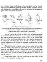
Work plan We will create the base of the support first. As you can see in the illustra-
tion below, the base consists of 7 parts that are welded together.
You could build this in the same manner we have worked in up until now:
create the parts first and then assemble them with the assembly command.
However, in this case that approach would be overly time-intensive and la-
borious. Just think about how you would shape the sloped supports, includ-
ing the dimensions. That approach would not be easy.
Fortunately, we have another option for modeling this design SolidWorks:
weldments. With the weldments command you can build standard tubes
SolidWorks for VMBO en MBO
Tutorial 9: Axle Support
3
and profiles within a single part. You can also save each part as a separate
file, if you want.
We will perform the next few steps:
1. First, we will create a round vertical tube, one of the bottom strips
and one of the diagonal square-shaped tubes.
2. After that step, we will add the weldments.
3. Next, we will copy the parts around the vertical tube, so there will
be three supports connected to the central tube.
4. Finally, we will make a hole at the top of the round tube.
SolidWorks for VMBO en MBO
Tutorial 9: Axle Support
4
1 Start SolidWorks and open
a new part.
2 Make sure the ‘Weldments’
function is available. As we
did when we worked with
SheetMetal in Tutorial 4,
we will now add the
‘Weldments’ keys to the
CommandManager.
1. Right-click on a tab in
the CommandManager.
2. Check the option
‘Weldments’.
3 Select the Front Plane, and
create a sketch as shown
on the right.
1 Draw a vertical line
from the origin.
2 Draw a horizontal line
from the origin.
3 Draw a diagonal line
beginning and ending
on the first two lines.
4 Set the dimensions in
the sketch.
4 Click on ‘Exit Sketch’ in the
CommandManager to end
the ‘Sketch’ command.
SolidWorks for VMBO en MBO
Tutorial 9: Axle Support
5
5 1. Click on ‘Weldments’ in
the CommandManager
2. Click on ‘Structural
Member’. With this
command you can add
tubes and profiles to a
construction.
6 Set the following features:
1 Select ‘ISO’ as the
‘Standard’.
2 Select ‘Pipe’ as the pro-
file ‘Type’.
3 Set the dimension to
‘33.7 x 4.0’.
4 Select the vertical line
in the sketch.
5 Click on OK.
Tip! There are a small number of pre-defined tubes and profiles in SolidWorks.
To be able to use exactly the right tube, there are two possibilities:
1. Create a new tube and add it to the library. You do this once and
then you can use this part every time you need it. Adding the part is
not difficult, but you will not have the access rights to do so in a
school environment. For this reason, we will not explain this proce-
dure as part of this tutorial.
2. The second option is to use an existing tube from the library, which
looks similar to the one you need. You can then adapt or alter the
dimensions to use it every time you need this part.
In this tutorial we will use the second method.
SolidWorks for VMBO en MBO
Tutorial 9: Axle Support
6
7 Find the feature (the tube)
you have just made in the
FeatureManager. This is
called ‘Structural Member1’
(the number can vary).
1 Click on the ‘+’ symbol
in front of the name of
the feature.
2 Right-click on the
sketch in this feature.
3 Click on Edit Sketch.
8 Click on Standard Views in
the View Orientation, and
then on Normal To.
9 Change the two dimen-
sions in the sketch:
1 The inside diameter
must be set to ‘64’.
2 The outside diameter
must be set to ‘70’.
3 Click on ‘Exit Sketch’.
SolidWorks for VMBO en MBO
Tutorial 9: Axle Support
7
10 Rotate the model so you
can get a clear view.
Click on ‘Weldments’ in the
CommandManager and
next on ‘Structural Mem-
ber’.
11 Set the following items in
the PropertyManager:
1 Select ‘ISO’ as the ‘Stan-
dard’.
2 Select the ‘rectangular
tube’ as the profile
‘Type’.
3 Select a size of ‘60 x 40
x 3.2’.
4 Select the horizontal line
in the sketch.
5 Click on ‘Locate Profile’.
SolidWorks for VMBO en MBO
Tutorial 9: Axle Support
8
12 SolidWorks will automati-
cally zoom in on the profile
now.
1 Click in the middle of the
bottom line of the pro-
file. The profile will move
upward.
2 Click on OK.
13 Open the sketch from this
rectangular tube, just as
you did previously (steps 7,
8 and 9).
This sketch looks pretty
complicated because of the
presence of a great num-
ber of relations.
We will convert the tube
into a strip.
14 Remove the inner contour
of the tube: click on a line
or bend and push the
<Del> delete key on the
keyboard.
SolidWorks for VMBO en MBO
Tutorial 9: Axle Support
9
15 Next, change the dimen-
sions:
1 The radius is set to ‘0.5’.
2 The height will be ‘4mm’.
The profile is no longer
the same height as the
bottom of the tube. This
is 0, because after you
have clicked on Exit
Sketch, as in step 4,
everything will be all
right again.
3 Change the width to
‘40mm’.
4 Click on ‘Exit Sketch’.
16 Now, we will create the
last tube. Click on ‘Weld-
ments’ in the Command-
Manager again and after
that on ‘Structural Mem-
ber’.
Use the same settings for
the tube. You do not have
to change any of them
1 Select the diagonal line.
2 Click on OK.
SolidWorks for VMBO en MBO
Tutorial 9: Axle Support
10
17 Open the sketch of the
tube to alter the dimen-
sions:
1 The radius of the tube is
set to ‘3mm’.
2 The thickness must be
set to ‘2mm’.
3 The height is ‘40mm’.
4 The width is ‘20mm’.
5 Click on ‘Exit Sketch’.
18 Save this file as:
base.SLDPRT.
19 Click on ‘Weldments’ in the
CommandManager and
next on ‘Trim/Extend’.
With this command we will
make sure that the tubes
will fit together (and do not
intersect each other any
more).
SolidWorks for VMBO en MBO
Tutorial 9: Axle Support
11
20 Set following items:
1 Make sure that the first
option End Trim is se-
lected in the ‘Corner
Type’ tab field :
2 Select the diagonal tube.
It will be mentioned in
the ‘Bodies to be
Trimmed’ field.
3 Click on the selection
field next to ‘Trimming
Boundary’. This will turn
active now (it will turn
blue).
4 Select the round tube.
5 Select the strip.
6 Make sure the option
‘Extend’ is checked.
7 When the model looks
OK, click on OK.
21 We still have to shorten
the bottom strip. Select
‘Trim/Extend’ in the Com-
mandManager again.
Most of the settings will be
still there from the last
time we did this.
1 Select the bottom strip.
2 Click on the selection
field next to ‘Trimming
Boundary’.
3 Select the vertical tube.
4 Click on OK.
SolidWorks for VMBO en MBO
Tutorial 9: Axle Support
12
22 To make the weldments,
click on ‘Weldments’ in the
CommandManager and
next on ‘Fillet Bead’.
23 Set the following items:
1 Set the weld dimension
to ‘3mm’.
2 Check the option ‘Tan-
gent propagation’: this
will make sure the weld
is made around the tube.
3 Select a plane from the
rectangular tube.
4 Click in the ‘Face Set2’
area to activate it (it will
turn blue).
5 Select a plane from the
strip.
6 Click on OK.
24 We will now weld the sec-
tion between the strip and
the tube. Click on ‘Fillet
Bead’ in the CommandMa-
nager. Most settings will
remain the same as in the
last weld we made.
1. Select the top plane of
the strip.
2. Click in the ‘Face Set2’
selection field to acti-
vate it (it will turn
blue).
3. Select the tube.
4. Click on OK.
SolidWorks for VMBO en MBO
Tutorial 9: Axle Support
13
25 We will now make the final
weld between the diagonal
tube and the round vertical
tube. We will not weld the
bottom section of this con-
nection.
1. Uncheck the option
‘Tangent propagation’.
2. Select the side plane
from the rectangular
tube.
3. Select the rounded
edge from the tube.
4. Select the top surface
plane from the tube.
26 Rotate the model so you
see the other side of this
part.
1. Select the rounded
edge.
2. Select the side plane.
3. Click on the ‘Face Set2’
selection field to acti-
vate it (it will turn
blue).
4. Select the vertical
tube.
5. Click on OK.
SolidWorks for VMBO en MBO
Tutorial 9: Axle Support
14
27 We can also hide the origi-
nal sketch that we used
before.
1 Click on the first
sketch in the Featu-
reManager.
2 Select Hide in the
pop-up menu.
28 One of the supports of the
product is now ready and
we will copy it twice
around the vertical tube.
We will use the centerline
from the tube to do so, but
first we have to show it.
1 Click on Hide/Show
Items.
2 Set the option Tempo-
rary Axes.
29 Click on ‘Features’ in the
CommandManager and se-
lect ‘Circular Pattern’. You
may have to open the ex-
tended menu first.
SolidWorks for VMBO en MBO
Tutorial 9: Axle Support
15
30 Set the next items in the
PropertyManager:
1 Click in the selection
area of the ‘Axis’ pat-
tern.
2 Select the centerline
from the vertical tube
as a rotation axis.
3 Set the number of items
in the pattern to ‘3’.
4 Open the menu ‘Bodies
to Pattern’.
31 Select all of the parts that
you want to rotate:
1 The rectangular tube.
2 The strip.
3 The weldment between
the strip and the tube.
4 The weldment between
the strip and the di-
agonal tube.
5 The weldment between
the vertical and diagon-
al tube.
6 When all parts are se-
lected, click on OK.
32 Finally, we have to create a
hole in the support.
1 Select ‘Front Plane’ in
the FeatureManager.
2 Click on Normal To in
the pop-up menu.
SolidWorks for VMBO en MBO
Tutorial 9: Axle Support
16
33 Make a sketch as in the il-
lustration on the right.
Draw a circle and put the
midpoint on the centerline
of the tube.
Set the two dimensions as
shown.
34 Make an Extruded Cut from
the sketch. Set the follow-
ing items in the Property-
Manager:
1 Set the option ‘Through
All’ in the ‘Direction1’
field (through the entire
model).
2 Activate menu ‘Direc-
tion2’ also, because the
hole has to be through
both sides.
3 Set the depth to
‘Through All’.
4 Click on OK.
35 This part is now ready.
Hide the Temporary Axes.
SolidWorks for VMBO en MBO
Tutorial 9: Axle Support
17
36 To hide the welding icons,
follow the next few steps:
1. Right-click on the map
‘Annotations’ in the
FeatureManager.
2. Uncheck the option
‘Display Annotations’.
37 Save the file.
Work plan The second part will be the expandable inner tube based on the drawing
below.
This part is not as complicated. We will build it following these steps:
1. Make the tube.
2. Make only one of the bigger holes.
SolidWorks for VMBO en MBO
Tutorial 9: Axle Support
18
3. Copy the holes.
4. Make the small hole.
38 Open a new part and start
sketching on the Top
Plane. The sketch consists
of one circle with the mid-
point at the origin.
39 Go to ‘Features’ and make
an ‘Extruded Boss/Base’.
Set following items in the
PropertyManager:
1 Set the length to
‘300mm’.
2 Activate the menu ‘Thin
Feature’. By doing so,
you will create a hollow
tube instead of a mas-
sive part.
3 By clicking ‘Reverse Di-
rection’ you can deter-
mine if the material is
added to the inside or
the outside of the circle.
Watch the model closely.
Make sure the material is
added at the inside of
the circle.
4 Set a thickness T1 of
‘3mm’.
5 Click on OK.
40 Display the centerline of
the tube: make sure the
view Temporary Axes is se-
lected.
SolidWorks for VMBO en MBO
Tutorial 9: Axle Support
19
41 Select the ‘Front Plane’ to
make a sketch on it and
make sure you have a clear
view of it.
42 Make a sketch as shown in
the illustration. Make sure
the midpoint of the circle is
on the centerline of the
tube.
43 Make an Extruded Cut from
this sketch. Set the follow-
ing items in the Property-
Manager:
1 Select the depth:
‘Through All’.
2 Activate the ‘Direction2’
menu.
3 Set depth ‘Through All’.
4 Click on OK.
44 Click on ‘Linear Pattern’ in
the CommandManager.
With this feature we will
copy the hole several
times.
SolidWorks for VMBO en MBO
Tutorial 9: Axle Support
20
45 1 First, you have to set the
direction in which the
elements should be co-
pied. For this, you have
to select the centerline
of the tube.
2 Set the distance be-
tween two holes to
‘35mm’.
3 Set the number to ‘6’.
4 Click on the ‘Features to
Pattern’ selection field.
Next, you have to select
the hole. You can do it in
the model, but it is easier
to do so in the FeatureMa-
nager.
5 Open the FeatureMa-
nager tree next to the
model.
6 Select the last feature in
the list.
7 When the preview looks
ok to you, click on OK.
46 Next, make the small hole
at the top. Select the Right
Plane and make the sketch
as shown.
Make an Extruded Cut in
two directions ‘Through
All’, like you did in Step 43.
SolidWorks for VMBO en MBO
Tutorial 9: Axle Support
21
47 To add a screw thread to
the hole, select the follow-
ing items in the pull-down
menu:
1. Open the pull-down
menu.
2. Click on ‘Insert’.
3. ‘Annotations’.
4. ‘Cosmetic Thread’.
48 Select the edges of the
holes in which you want to
put the thread.
3. Set the depth to
‘Through’.
4. Set the diameter to ‘6’.
5. Click on OK.
49 Hide the Temporary Axes
again and save the model
as: pipe.SLDPRT
Work plan The next part we will build is the support block on top. We will create this
part from two features: an extrusion and a rotation. After that, we will
make the countersink holes with the Hole Wizard. The difficulty with this
part is that you have to draw two different sketches and join them togeth-
SolidWorks for VMBO en MBO
Tutorial 9: Axle Support
22
er.
50 Open a new part, select
the Front Plane and make
a sketch.
Draw a vertical centerline
from the origin up (length
of about 40mm).
51 Next, make a horizontal
line (not a centerline) ac-
cording to the sketch as
shown on the right.
1. The first line is a hori-
zontal line from the
origin with a length of
approximately 40mm.
2. Draw the rest of the
sketch from this point
on. The sizes are not
important yet. Only
make sure that the end
of the last line is on
the centerline again.
SolidWorks for VMBO en MBO
Tutorial 9: Axle Support
23
52 Add the exact dimensions
with Smart Dimension.
Look at the illustration.
If the sketch from the pre-
vious step was not drawn
very accurately, it is possi-
ble that you will see
strange things happen. The
best you can do is throw
away (<Del> delete the
sketch) and start again at
Step 50. The most impor-
tant part of this drawing is
the first horizontal line: this
should be about 40mm
long.
53 Next, select the entire
sketch: click at a point on
the left top and hold the
mouse button while drag-
ging the cursor to the bot-
tom right. You will draw a
frame around the sketch;
notice that all parts should
be included in this frame.
54 Click on ‘Mirror Entities’ in
the CommandManager.
When you follow the cor-
rect steps, the sketch will
be mirrored around the
centerline from Step 52.
Did you select more or less
than one centerline? The
sketch will not be mirrored
immediately. You will have
to select one line in the
PropertyManager to use as
a mirror axis.
SolidWorks for VMBO en MBO
Tutorial 9: Axle Support
24
55 Make an Extruded
Boss/Base from this
sketch. Set the following
features in the Property-
Manager:
1. Select ‘Mid Plane’ for
‘Direction1’.
2. Set the length to ‘65’.
3. Click on OK.
Tip! Using the Mid Plane option, the sketch will be extruded in two directions
with equal length. This is very convenient when creating symmetrical prod-
ucts (like this one) because the origin will remain in the middle of the prod-
uct. This again is very convenient if you want to mirror parts later on.
You could also get the same results by setting ‘Direction2’ in the Property-
Manager. You will get more options that way, so it is less applicable to this
situation.
56 Start a new sketch on the
Front Plane.
Draw a rectangle first, as
shown in the drawing on
the right. The left top cor-
ner is at the origin.
SolidWorks for VMBO en MBO
Tutorial 9: Axle Support
25