BÁO CÁO NGHIÊN CỨU VỀ BỘ CHUYỂN ĐỔI MA TRẬN TẦN SỐ CAO (High Frequency Matrix Converter)
Bạn đang xem bản rút gọn của tài liệu. Xem và tải ngay bản đầy đủ của tài liệu tại đây (457.48 KB, 35 trang )
The University of Sheffield
Electrical Machines & Drives Research Group
1
High Frequency Matrix Converter
High Frequency Matrix Converter
Nam Nguyen-Quang
eBook for You
The University of Sheffield
Electrical Machines & Drives Research Group
2
• Background information
• Proposed converter
• Results to-date
• Conclusion
OVERVIEW
eBook for You
The University of Sheffield
Electrical Machines & Drives Research Group
3
• Induction Heating (IH)
Î Basic Principles
Î Resonant Tanks
• Conventional Converters for IH
Î Current Source Inverter (CSI)
Î Voltage Source Inverter (VSI)
BACKGROUND INFORMATION
eBook for You
The University of Sheffield
Electrical Machines & Drives Research Group
4
• A coil (work-head) creates a magnetic field, which
induces a current in a conductor (work-piece)
• Large current is required Ö the use of resonant
tanks
• Loose coupling between
the work-head and the
work-piece
Ö high
quality factor
INDUCTION HEATING – BASIC PRINCIPLES
eBook for You
The University of Sheffield
Electrical Machines & Drives Research Group
5
• Skin depth: the depth from surface, at which the
current density is about 1/3 of its surface value.
• Skin depth decreases when frequency increases.
• Frequency bands have been defined for IH:
Î Supply-frequency: 50 – 540 Hz
Î Medium frequency: 500 Hz – 50 kHz
Î Radio frequency: 50 kHz – 10 MHz
Î Microwave: 10 MHz upwards
INDUCTION HEATING – BASIC PRINCIPLES
eBook for You
The University of Sheffield
Electrical Machines & Drives Research Group
6
INDUCTION HEATING – RESONANT TANKS
Series resonant tank
• High impedance at
high frequency
• Used with VSIs
Parallel resonant tank
• Low impedance at high
frequency
• Used with CSIs
C L
R
C
L
R
eBook for You
The University of Sheffield
Electrical Machines & Drives Research Group
7
• Higher order resonant tanks have been used
• Most widely reported and useful is the LLC tank
INDUCTION HEATING – RESONANT TANKS
C
L
2
R
L
1
Î High impedance at
high frequency, can
be used with VSIs
Î Large current can
circulate through C
and L
2
eBook for You
The University of Sheffield
Electrical Machines & Drives Research Group
8
• First widely used topology
• Run at the resonant frequency
• Power is only controlled by amplitude modulation
CONVENTIONAL CONVERTERS – CSI
C
L
RI
eBook for You
The University of Sheffield
Electrical Machines & Drives Research Group
9
• Two utility supply interfaces
CONVENTIONAL CONVERTERS – CSI
Low Power High Power
eBook for You
The University of Sheffield
Electrical Machines & Drives Research Group
10
• Advantages
Î Low reactive power flow
Î Constant operating frequency
• Disadvantages
Î Effect of stray inductance: limit on frequency,
and physical cable length
Î High switching losses
Î Non-unity power factor, high harmonic
distortion
CONVENTIONAL CONVERTERS – CSI
eBook for You
The University of Sheffield
Electrical Machines & Drives Research Group
11
• More emergent technology
• Power can be controlled by frequency, amplitude,
or phase angle (phase-shift) modulation
CONVENTIONAL CONVERTERS – VSI
C L
RV
eBook for You
The University of Sheffield
Electrical Machines & Drives Research Group
0 1 2 3 4 5 6 7 8 9 10
S1
S2
S3
S4
Gate signals
0 1 2 3 4 5 6 7 8 9 10
-30
-20
-10
0
10
20
30
Time (
μ
s)
Output voltage and current
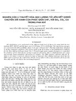
12
• Frequency modulation
Î The simplest and most straightforward method
Î An inductive load is needed for ZVS Ö an
above resonance operating condition
CONVENTIONAL CONVERTERS – VSI
eBook for You
The University of Sheffield
Electrical Machines & Drives Research Group
13
• Amplitude modulation
Î Varying the DC link voltage
Î Operating just above the resonant frequency
CONVENTIONAL CONVERTERS – VSI
eBook for You
The University of Sheffield
Electrical Machines & Drives Research Group
14
• Phase angle (phase-shift) modulation: Many
variants, with or without lossless snubbers
CONVENTIONAL CONVERTERS – VSI
0 1 2 3 4 5 6 7 8 9 10
S1
S2
S3
S4
Gate signals
0 1 2 3 4 5 6 7 8 9 10
-30
-20
-10
0
10
20
30
Time (
μ
s)
Output voltage and current
Current
Voltage
0 1 2 3 4 5 6 7 8 9 10
S1
S2
S3
S4
Gate signals
0 1 2 3 4 5 6 7 8 9 10
-30
-20
-10
0
10
20
30
Time (
μ
s)
Output voltage and current
Current
Voltage
eBook for You
The University of Sheffield
Electrical Machines & Drives Research Group
0 1 2 3 4 5 6 7 8 9 10
S1
S2
S3
S4
Gate signals
0 1 2 3 4 5 6 7 8 9 10
-30
-20
-10
0
10
20
30
Time (
μ
s)
Output voltage and current
Current
Voltage
15
• Using lossless snubbers, ZVS in both legs
CONVENTIONAL CONVERTERS – VSI
eBook for You
The University of Sheffield
Electrical Machines & Drives Research Group
16
• Advantages
Î Many power control methods, some with ZVS
or ZCS, stray capacitances can be utilised
Î Stray inductances can be utilised
• Disadvantages
Î Large current harmonics at line side, non-unity
power factor
Î Bulky and unreliable DC link capacitor
CONVENTIONAL CONVERTERS – VSI
eBook for You
The University of Sheffield
Electrical Machines & Drives Research Group
17
• Basis for single phase high frequency matrix
converter
CONVENTIONAL CONVERTERS – VSI
Rectifier LLC Resonant TankH-Bridge
Inverter
Line
Filter
C
L
2
R
L
1
V
Source
eBook for You
The University of Sheffield
Electrical Machines & Drives Research Group
18
• Single-phase to single-phase matrix converter
(Single phase MC)
Î Topology
Î Problems
• Three-phase to single-phase matrix converter
(Three phase MC)
Î Topology
Î Problems
PROPOSED CONVERTER
eBook for You
The University of Sheffield
Electrical Machines & Drives Research Group
19
• Topology
SINGLE PHASE MC – TOPOLOGY
V
A
V
B
eBook for You
The University of Sheffield
Electrical Machines & Drives Research Group
20
• The converter is expected to possess
Î Unity power factor, sinusoidal input current
Î ZVS and ZCS in one row, ZVS in other row
Î PWM power control over a wide range
SINGLE PHASE MC – TOPOLOGY
eBook for You
The University of Sheffield
Electrical Machines & Drives Research Group
21
• Commutation problem: Modified voltage
commutation
• Utility supply interface: Small line filter
• Power control: PWM with soft switching
SINGLE PHASE MC – PROBLEMS
eBook for You
The University of Sheffield
Electrical Machines & Drives Research Group
22
• Topology
THREE PHASE MC – TOPOLOGY
V
A
V
B
V
C
eBook for You
The University of Sheffield
Electrical Machines & Drives Research Group
23
• Commutation problem: directly applying
switching pattern of single-phase version may
create large distortion in input currents
• Utility supply inferface: small line filter
• Power control: PWM control with soft switching is
preferrable
THREE PHASE MC – PROBLEMS
eBook for You
The University of Sheffield
Electrical Machines & Drives Research Group
24
• Literature survey
• Reference system
• Simulations of single phase MC
RESULTS TO-DATE
eBook for You
The University of Sheffield
Electrical Machines & Drives Research Group
25
• Principles of induction heating
• Resonant converters for induction heating
• Analysis methods for resonant-mode inverters
• Utility interfaces for converters
• Other converters
RESULTS – LITERATURE SURVEY
eBook for You