Materials for the Hydrogen Economy (2007) Episode 3 pdf
Bạn đang xem bản rút gọn của tài liệu. Xem và tải ngay bản đầy đủ của tài liệu tại đây (2.01 MB, 30 trang )
36 Materials for the Hydrogen Economy
24. Ferguson, C.R., Falsetti, J.S., and Volk, W.P., Rening Gasication: Petroleum Coke
to Fertilizer at Farmland’s Coffeyville, Kansas Renery, Paper AM-99-13, paper pre
-
sented at the NPRA 1999 Annual Meeting, San Antonio, TX, March 21–23, 1999.
25. Doctor, R.O., Molburg, J.C., Brockmeier, N.F., and Stiegel, G.J., Designing for Hydro
-
gen, Electricity and CO
2
Recovery from a Shell Gasication-Based System, paper pre-
sented at the Proceedings of the 18th Annual International Pittsburgh Coal Conference,
Newcastle, New South Wales, Australia, December 4–7, 2001.
26. Volkmann, D. and Just, T., Refractories for Gasication Reactors: A Gasication Tech
-
nology Supplier’s Point of View,
Refractories Applications and News, 9, 11–16, 2004.
27. Rezaie, A., Headrick, W.L., and Fahrenholtz, W.G., Identication of refractories for
high temperature black liquor gasiers, in
Proceedings of the Unied International
Technical Conference on Refractories, UNITECR ’05, Orlando, FL, November 2005,
4 pp.
28. Taber, W.A., Refractories for Gasication,
Refractories Applications and News, 8,
18–22, 2003.
29. U.S. Department of Energy,
Gasication Markets and Technologies — Present and
Future: An Industry Perspective, Report 0447, July 2002, pp. 1–53.
30. Johnson, R.C. and Crowley, M.S., State of the art refractory linings for hydrogen
reformer vessels, in
Proceedings of the Unied International Technical Conference on
Refractories, UNITECR ’05, Orlando, FL, November 2005, 4 pp.
31. Raymon, N.S. and Saddler, L.Y., III, Refractory Linings Materials for Coal Gasiers:
A Literature Review of Reactions Involving High-Temperature Gas and Alkali Metal
Vapors, USBM Information Circular 8721, 22, 1976.
32. Bakker, W.T., Refractories for Present and Future Electric Power Plants,
Key Engineer-
ing Materials, 88, 41–70, 1993.
33. U.S. Department of Energy, Fossil Energy: DOE’s Hydrogen from Coal R+D Program,
available at www.fe.doe.gov/programs/fuels/hydrogen/Hydrogen_ from_coal_R+D,
August 1, 2005.
5024.indb 36 11/18/07 5:44:52 PM
37
2
Materials for Water
Electrolysis Cells
Paul A. Lessing
ConTenTs
2.1 Background of Hydrogen Generation via Electrolysis 37
2.2 Low-Temperature Electrolysis of Water Solutions 38
2.3 Low-Temperature PEM-Type Electrolyzers 41
2.4 Low-Temperature Inorganic Membrane Electrolyzers 42
2.5 Moderate-Temperature Inorganic Membrane Electrolyzers 44
2.5.1 Moderate-Temperature Oxygen Ion Conductors 46
2.5.2 Moderate-Temperature Proton Conductors 48
2.5.3 Moderate-Temperature Bipolar Plates (Interconnects) 50
2.6 High-Temperature Inorganic Membrane Electrolyzers 52
2.6.1 High-Temperature Oxygen Ion Conductors 52
Acknowledgments 53
References 54
2.1 baCkground of hydrogen
generaTIon vIa eleCTrolysIs
Hydrogen generation can be accomplished via traditional DC electrolysis of aque-
ous solutions at temperatures less than about 100°C. However, electrolysis of steam
can also be accomplished at higher temperatures at the cathode of electrolytic cells
utilizing solid membranes. The solid membranes typically are electronic insulators
and need to be gas-tight (hermetic), but have the special property of being able to
conduct ions via fast diffusion through the solid. Generally the cells (cathode/elec-
trolyte/anode) are known by the chemical name of their solid electrolytes. It has
been found for some operating hydrogen fuel cell anode/electrolyte/cathode systems
that the fuel cell reactions at the electrodes are reversible and can be operated in an
electrolysis mode. However, reversibility has not been demonstrated for all cathode/
electrolyte/anode combinations.
Hydrogen production via conventional electrolysis largely depends upon the
availability of cheap electricity (e.g., from hydroelectric generators). Consequently,
only about 5% of the world hydrogen production is via electrolysis. The only com-
plete hydrogen production process that is free of CO
2
emissions is water electrolysis
(if the electricity is derived from nuclear or renewable fuels). However, 97% of the
hydrogen currently produced is ultimately derived from fossil energy. Currently, the
5024.indb 37 11/18/07 5:44:52 PM
38 Materials for the Hydrogen Economy
most widely used and economical process is steam reforming of natural gas, a pro-
cess that results in CO
2
emissions.
2.2 loW-TemPeraTure eleCTrolysIs of WaTer soluTIons
The reversible electrical potential (∆G/nF = E
rev
) to split the O–H bond in water is
1.229 V. In addition, heat is needed for the operation of an electrolysis cell. If the
heat energy is supplied in the form of electrical energy, then the thermal potential
is 0.252 V (at standard conditions), and this voltage must be added to E
rev
(i.e., add
entropic term T∆S to ∆G). The (theoretical) decomposition potential for water at
standard conditions (for ∆H
≅ ∆H°) is then 1.480 V. This is shown in gure 2.1.
Anode and cathode reactions for electrolysis (see gure 2.1) are:
Anode: 2 OH
–
→ 1/2 O
2
+ H
2
O + 2 e
–
(2.1)
Cathode: 2 H
2
O + 2 e
–
→ H
2
+ 2 OH
–
(2.2)
For alkaline electrolysis, OH
–
ions must be able to move through the membrane
(under inuence of the electric eld) from the cathode chamber into the anode cham
-
ber to supply OH
–
to participate in the reaction (equation 2.1) at the anode.
Irreversible processes that occur at the anode and cathode and the electrical
resistance of the cells cause the actual decomposition potential (voltage) to increase
to about 1.85 to 2.05 V. This means that the electrolysis efciency will be between 72
and 80%. The total electrical resistance of the cell is dependent upon the conductiv
-
ity of the electrolyte, the ionic permeability of the gas-tight diaphragm that separates
the anodic region from the cathodic region, and the current density (normally in the
fairly moderate range of 0.1 to 0.3 A cm
–2
). Higher KOH concentrations (up to 47%)
yield higher conductivity, but this usually greatly increases the corrosion of various
cell components.
Common aqueous electrolytes are better conductors at slightly elevated tempera
-
tures (70 to 90°C), so the electrolysis cells are operated at these conditions. The orig
-
inal discovery of electrolytic water splitting used acidic (diluted H
2
SO
4
) water, but in
industrial plants an alkaline (e.g., 25 wt% KOH) medium is preferred because cor
-
rosion is more easily controlled and cheaper materials can be utilized. Diaphragms
(see gure 2.1) are made either of polymers (polysulfonate type) or from porous
ceramics (e.g., asbestos or barium titanate). In some congurations, the electrodes
are placed directly at the surface of the diaphragm to reduce the voltage drop and
minimize heat losses. The cathode material has historically been made from steel
and the anode material from nickel or nickel-coated steel. The cell walls have been
made from carbon steel. The heat generated in the electrolyte must be removed by
water cooling. Pure water has to be added to the cell to replace the water that is dis
-
sociated to hydrogen and oxygen gases.
In order to reduce the actual cell voltage downward toward the 1.48 value (reduce
energy consumption), many different catalytic materials have been examined for
use as anodes or cathodes (or coatings on underlying electrodes). Research was
conducted in Germany in the 1980s and 1990s on advanced materials and designs
5024.indb 38 11/18/07 5:44:53 PM
Materials for Water Electrolysis Cells 39
for alkaline water electrolysis cells.
1
Electronically conductive, metal oxides (e.g.,
La
0.5
Sr
0.5
Co
3
, LaNi
0.2
Co
0.8
O
3
, or RuO
2
) were investigated for use as anodes and vari-
ous metal alloys (e.g., Ni/Co, ne Raney iron, Raney Ni/Co, Pt-black platinized Ni)
were evaluated by Wendt et al.
2
for possible use as cathodes. Raney nickel is a highly
porous nickel coated onto supporting nickel or stainless steel electrodes, and can be
produced by a number of different methods.
3
Many times these activated electrodes
provide enhanced performance, but they can have a short lifetime.
In recent years (1999 to present), experiments on metal coatings (e.g., Ni-Fe-Mo,
Ni-Fe, or Ni-Co alloys) as catalysts for the cathode (in order to reduce polarization)
have been conducted.
4
Mild steel is often used as the underlying substrates. Materials
evaluated for catalysts have included hydrogen storage alloys (Mm = Misch metal;
Ni
3.6
Co
0.75
Mn
0.4
Al
0.27
, LaNi
4.9
Si
0.1
, and Ti
2
Ni). These alloys were layered on top of a
nickel-molybdenum coating with an underlying nickel foam substrate and seem to
show promise for both electrocatalytic activity and stability.
5
Work on mixed-metal
oxide catalysts (in order to reduce anode polarizations) has included deposition (e.g.,
sol-gel method) of spinel (NiCo
2
O4) on substrates
6
of mild steel, nickel, or titanium.
These layered structures demonstrated a high (compared to Ni) and stable activity
(during 200 h of operation).
There has been some recent interest in selective electrolysis of seawater (e.g.,
electrolytes of 0.5
M NaCl @ pH 12) in desert coastal areas (no freshwater) to pro-
duce hydrogen (for possible use with carbon dioxide to produce methane) and oxygen
(not chlorine). In a study by Abdel Ghany et al.,
7
anodes of Mn
1–x
Mo
x
O
2+x
(on IrO
2
/Ti
substrates) were prepared using anodic deposition from MnSO
4
-Na
2
MoO
4
solutions.
When running at a current density of 1,000 Am
–2
at 30°C, an increase in solution
temperature resulted in dissolution of the oxides as molybdate and permanganate
ions. Additions of iron to the oxides greatly aided in the chemical stability (30 to
90°C range) and also enhanced the oxygen evolution efciency.
The uorinated polymer polytetrauorethylene (PTFE) diaphragm is stable in
hot KOH; however, membranes made with this material tend to become gas clogged
and are not suitable as diaphragm materials. Wendt and Hofmann
8
conducted a study
to replace the conventional asbestos diaphragm (that dissolves in caustic KOH at
temperatures above 90°C) with polymer-bonded (PTFE-type) composites. These
composites included an inorganic material (ZrO
2
, Ca- or Ba-titanate, or K-hexatita-
nate). The polymer-bonded materials showed too high of an electrical resistance for
“sandwich” cell designs, so they were not pursued. The polymer-bonded materials
might, however, be used as gaskets.
The electrolysis diaphragm generally is fabricated to include ne pores (vs. being
an ionic (OH
–
) conductor) such that it passes electrolytes. But, it must prevent unhin-
dered intermixing of the catholyte and anolyte since these liquids are really a two-
phase mixture of electrolyte with a dispersion of gas bubbles (hydrogen and oxygen,
respectively) and hydrogen gas cannot be mixed with oxygen gas. In order to operate
efciently, the diaphragm must not be clogged by gas bubbles that may intrude into
the pore mouths or that may precipitate out within the pores from supersaturated
(high-pressure operation) electrolyte solutions. The diaphragm must also offer suf
-
ciently high hydrodynamic resistance to retard intermixing of oxygen-saturated
5024.indb 39 11/18/07 5:44:54 PM
40 Materials for the Hydrogen Economy
fIgure 2.1 (a) Schematic of water (alkaline) electrolysis. (b) Two large (200 Nm
3
/h) atmo-
spheric, alkaline, multicell electrolysis stacks generating hydrogen at the Norsk Hydro Company.
5024.indb 40 11/18/07 5:44:56 PM
Materials for Water Electrolysis Cells 41
anolyte with hydrogen-saturated catholyte due to any pressure differences between
the two chambers and also prevent diffusion of gas molecules.
Diaphragms made of sintered metals are not easily incorporated into a bipolar-
type cell and do not permit zero-gap cell geometries. Therefore, Wendt and Hof
-
mann
8
further investigated metal-ceramic cermets. Nickel (low carbon, low sulfur)
was the most stable against corrosion (220°C) of the various other metals that were
evaluated (titanium, zirconium). Nickel mesh-supported, sintered nickel cermets uti
-
lizing NiTiO
3
or BaTiO
3
were fabricated and showed good in-cell performance.
Norsk Hydro Electrolyzers (NHE) in Norway is a leading producer of alkaline
electrolyzers (see gure 2.1b, where individual cells are linked in series electrically
and geometrically in a bipolar lter press conguration). Kreuter and Hofmann
9
dis-
cuss the efciency, operability, safety, and economics of scaling up alkaline-type
electrolysis cells to large plants, including the advanced pressurized (30-bar) alka
-
line prototype built by Gesellschaft fur Hochleistungselektrolyseure zur Wasserstof
-
ferzeugung (GHW) in Germany.
2.3 loW-TemPeraTure Pem-TyPe eleCTrolyzers
Proton exchange membrane or PEM-type water electrolyzers utilize thin lms (e.g.,
0.25 mm) of a proton-conducting ion exchange material instead of a liquid electro
-
lyte. When a reverse polarity is applied to a PEM fuel cell, the fuel cell reactions are
reversed and become water electrolysis reactions (see equations 2.6 to 2.8). PEM fuel
cells have been the subject of research and development for decades. In the 1960s
NASA used PEM cells for their Hope, Gemini, and Biosatellite missions. After a
lull in the 1980s, a rush of development began in the early 1990s for transporta
-
tion applications. This was initiated by improvements in bonded electrodes, which
enabled much higher current densities. These improvements can be advantageous to
PEM cells used as electrolyzers.
The PEM cells typically use sulfonated polymer (e.g., Naon™) electrolytes that
conduct the protons away from the anode to the cathode (in electrolysis mode). For
smaller generators, the solid polymer can be more attractive than a dangerous, caus
-
tic electrolyte. A complicating factor is that the solid-state conduction of the protons
is accompanied by multiple water molecules (H
2
O)
n
H
+
. Also, the membrane must
be kept hydrated to sustain the conduction mechanism. Therefore, water recycling
becomes a large consideration since water is constantly removed from the anode
and reappears at the cathode (mixed with the hydrogen). At temperatures less than
100°C, gaseous hydrogen is easily removed from liquid water, but the hydrogen still
contains water vapor that most likely requires dehumidication (e.g., pressure swing
adsorption dryer). Electrodes generally have utilized nely divided platinum black
or, more recently, IrO
2
or RuO
2
(for increased electronic conductivity) as catalysts.
10
Research is currently being conducted into PEM-type membranes that have bet
-
ter kinetics, yet are chemically stable at elevated temperatures such that they could
operate in steam.
11
PEM water electrolysis cells have a potential advantage over traditional low-tem-
perature electrolysis cells (e.g., KOH in water electrolytes with palladium, titanium,
or alternative metal or ceramic electrodes
12,13
) because PEM devices have been
5024.indb 41 11/18/07 5:44:57 PM
42 Materials for the Hydrogen Economy
shown to be reversible. They can “load level” by generating electricity from hydro-
gen (and oxygen) operating as a fuel cell when needed (peak) and reverse to operate
as an electrolyzer by consuming electricity to produce hydrogen (and oxygen). This
is convenient if excess electricity is available during low periods of consumption
(off-peak).
14
PEM electrolysis cells could also be used in hybrid systems utilizing
solar energy.
15
Because of all the developments in PEM fuel cell technology, small PEM elec-
trolysis plants are becoming available. Small (up to 240 SCF/h = 6 Nm
3
/h) PEM
electrolysis units are now available commercially from Proton Energy Systems,
16
and efforts are being made to reduce their production cost.
17
Hamilton Sundstrand
18
has been manufacturing SPE™ electrolysis systems (PEM) for a number of years for
the U.S. Navy. Treadwell Corp.
19
has recently developed PEM generators (20 to 170
standard liters per minute or SLPM) at pressures of up to 1,100 psi. Hydrogenics
Corp.
20
is manufacturing two units (1.1 and 30 Nm
3
/h), and Giner Electrochemical
Systems
21
is developing a PEM electrolysis unit. Some critical attention to cell stack
lifetime must be paid in light of the degradation and thinning of Naon 117 PEM
electrolytes identied in long-term tests in Switzerland
22
(two 100-kW PEM water
electrolyzer plants). The thinning process proceeded via dissolution of the mem
-
brane from the interface between the cathode and the membrane. The degradation
rate depended upon the position within an individual cell as well as the position of
the cell in the electrolyzer stack.
Ando and Tanaka
23
have recently used a Naon electrolyte in electrolysis mode
to decompose two water molecules to simultaneously generate one molecule of
hydrogen and one of hydrogen peroxide (used in paper/pulp and chemical indus
-
tries). They do this by using a high applied voltage (1.77 to 2.00 V) in a two-electron
transfer process (cathode, 2 e
–
+ 2 H
+
→ H
2
; anode, 2 H
2
O → HOOH + 2 H
+
+ 2 e
–
)
and a NaOH anolyte collection solution. No oxygen is generated.
2.4 loW-TemPeraTure InorganIC
membrane eleCTrolyzers
Electrolyzers operated at low temperatures do not take full advantage of thermody-
namic efciency advantages. The required cell voltage drops considerably (to E
o
°
= 0.9 V at 927°C) because of the positive entropy value (∆G° = ∆H° – T∆S°) when
operating at high temperatures. However, sealing bipolar plate devices should be
easier at low temperatures since thermal cycling would not result in high stresses
due to thermal expansion mismatches between cell components and sealing mate
-
rial. Also, inorganic membranes will be more chemically stable in the 200 to 300°C
temperature range than most organic proton-conducting membranes. A typical pres
-
surized-water nuclear reactor
24
heats water from 285°C to 306°C (at 2150 psia) in its
core and might be a heat source (heat-exchanged steam at temperatures signicantly
lower than the core temperature) for a low-temperature electrolysis device.
Solid inorganic materials exhibiting fast proton conduction at low temperatures
seem to be more prevalent than fast oxygen ion conductors. Some proton-conducting
glasses achieve high proton mobility due to incorporation of water (bonded to POH
groups). These glasses can be fabricated by sol-gel techniques at low temperatures.
5024.indb 42 11/18/07 5:44:58 PM
Materials for Water Electrolysis Cells 43
However, the gels are deliquescent and also are easily fractured into pieces when
heated.
25
This limits the practical application of these glasses to very low tempera-
tures, and therefore limits the ux values of hydrogen that can be achieved. Fabri
-
cation of proton-exchanged
β"-alumina compositions is difcult because waters of
hydration are lost during ring, and therefore the crystal structure is irreversibly
destroyed.
26
One approach used to solve this problem, for β"-alumina, has been to
fabricate a potassium ion crystal structure by ring to high temperatures. Then, at
room temperature, protons can be electrochemically ion exchanged into the crystals
from a mineral acid.
27,28
Since the potassium ion is larger than the sodium ion, using
the potassium composition lessens lattice strain during the proton exchange process.
In these oxide ceramics, two protonic species can exist. The rst type is a H
2
O
molecule associated with a proton as a hydronium ion (H
3
O
+
). The second type is a
proton bound to an oxygen ion of the crystal lattice (=OH
+
).
Ion exchange techniques have also been applied to compositions of the family
of three-dimensional sodium ion-conducting “NASICON.” NASICON is a three-
dimensional conductor, whereas
β"-alumina is a two-dimensional conductor. NASI-
CON membranes have primarily been used for efciently producing caustic (NaOH)
from concentrated sodium salts dissolved in water.
29
NASICON is a family of com-
positions; the original NASICONs were solid solutions derived from NaZr
2
P
3
O
12
by partial replacement of P by Si with Na excess to balance the negative charges to
generate the formula Na
1+x
Zr
2
P
3–x
Si
x
O
12
(0 ≤ x ≤ 3). NASICON compositions have
been prepared by a sol-gel route, and then the membranes ion exchanged with hydro
-
nium ions.
30
However, severe difculties with cracking of dense membranes occur
during the ion exchange.
31
Recently, a sintered proton-exchanged NASICON-type
composition known as PRONAS™ has become available in experimental quantities
from a commercial supplier.
32
This material was designed for use in liquid systems,
but reportedly has been tested as a membrane for hydrogen gas separation. Presum
-
ably, the PRONAS composition was sintered and then proton exchanged at room
temperature; however, no chemical composition or processing details are available
at this date.
Historically, there have been only a few articles regarding materials (including
various phosphates) exhibiting fast proton conduction at low temperatures. These
include early reviews by Farrington and Briant
33
and McGeehin and Hooper.
34
McGeehin concludes that slow proton conduction is associated with the instabil
-
ity of the hydride (H
–
) ion in oxidizing environments and the ease with which the
small proton (H
+
) is trapped. Problems associated with fabricating dense, poly-
crystalline membranes of these materials should be parallel to those of NASI
-
CON. The low-temperature proton conductivity of materials such as CsHSO
4
,
35
M
3
H(XO
4
)
2
(M = K, Rb, Cs, and X = S, Se),
36
CsH
2
PO
4
,
37,38
H
5
GeMo
11
VO
4
0.24
H
2
O,
39
H
x
MoO
3
(0 < x < 2)
40
(hydrogen molybdenum bronze), or the similar H
0.46
WO
3
(hydrogen tungsten bronze) have been studied. However, no work seems to
be extant related to fabrication of these materials into membranes for fuel cell or
steam electrolysis applications.
5024.indb 43 11/18/07 5:44:58 PM
44 Materials for the Hydrogen Economy
2.5 moderaTe-TemPeraTure InorganIC
membrane eleCTrolyzers
Steam electrolysis is feasible at moderate temperatures using cells constructed with
solid inorganic (ceramic) membranes. These temperatures could range from approx
-
imately 500 to 800°C using ceramic membranes that are either oxygen ion or proton
conductors. This temperature regime is a good match to approximate coolant outlet
temperatures that would be generated by various experimental nuclear reactor con
-
cepts,
41
such as Gas-Cooled Fast Reactor System (GFR) at 850°C, Lead-Cooled Fast
Reactor System (LFR) at 550°C (perhaps up to 800°C), Molten Salt Reactor (MSR)
at 700°C, Sodium-Cooled Fast Reactor System (SFR) at 550°C, and Supercritical-
Water-Cooled Reactor System (SCWR) at 550°C. Of course the steam temperature
in a secondary cooling loop would be somewhat less than a reactor’s coolant outlet
temperature due to heat exchanger inefciencies.
One approach to enable operation at lower temperatures while using traditional
materials like cubic phase zirconia is to reduce the thickness of zirconia electrolyte
using any one of a number of diverse fabrication techniques, such as tape calendar
-
ing,
42
vacuum plasma spraying,
43,44
reactive sputtering,
45
pulsed-laser plasma evap-
oration,
46
or chemical vapor deposition (CVD).
47
Very thin electrolytes generally
have to be supported by a thicker, porous electrode. Wang
45
mentions the problem
of microporosity that is normally observed in zirconia electrolytes when using the
evaporative-type deposition techniques, whereas CVD-type coatings are generally
much more hermetic. INL has performed experiments with Liquid Injected Plasma
Deposition (LIPD; see gure 2.2) where mixed cation salts (e.g., metal nitrates) are
dissolved in water or alcohol and pumped to be misted into a plasma plume. The
metal nitrates are decomposed in the plasma to form very ne mixed-metal oxide
particles. These particles are melted in the plasma and are concurrently deposited on
a substrate. Porous layers that can be used as electrodes are easily formed. Efforts
are ongoing to produce thin, dense/hermetic layers that would be an inexpensive
substitute for CVD coatings. A mock-up of the experimental apparatus in use at INL
is shown in gure 2.3. For illustration, it does not show the plasma torch, but it does
show the programmable syringe pump to control the injection rate of liquid solution
(left), liquid/air injection nozzles (red tips), holder with injection ports (including
nozzle shroud), and sample to be coated (in holder at right).
The other approach to operating at lower temperatures is to develop new electro
-
lyte compositions with higher ionic conductivities (for a given temperature range).
Even though these electrolytes have higher ionic conductivities than zirconia at tem
-
peratures in the 600 to 800°C range, they generally have not been applied at higher
temperatures for a variety of reasons: (1) low activation energy for diffusion such
that, while ionic conductivity is higher than zirconia at moderate temperatures, it can
be lower than zirconia at high temperatures; (2) chemical instabilities, interdiffusion,
or reactions with other cell components (electrodes, bipolar plate, sealants); (3) poor
high-temperature mechanical or creep properties; or (4) a desire to use the electro
-
lyte in cell stacks in conjunction with low-cost metal bipolar plates that operate best
at low to moderate temperatures (due to problems with low-conductivity oxidation
layers formed at high temperatures).
5024.indb 44 11/18/07 5:44:59 PM
Materials for Water Electrolysis Cells 45
dc plasma torch
cooling water out
gas inlet
liquid reactant atomize
r
cooling channel
cooling water in
Plasma Torch LIPD of Coating
fIgure 2.2 Schematic of Liquid Injected Plasma Deposition technique.
fIgure 2.3 Equipment in use at INL for Liquid Injected Plasma Deposition.
5024.indb 45 11/18/07 5:45:01 PM
46 Materials for the Hydrogen Economy
Over the last decade there has been signicant R&D to reduce the operating
temperature of solid-oxide fuel cells (SOFCs). This primarily is intended to enable
the use of cheaper and higher-conductivity (compared to electronically conductive
ceramics like doped lanthanum chromite) bipolar plates made from metal alloys and
at the same time minimizing formation of the low-conductivity metal oxide layers
that greatly increase IR (current × resistance) losses in a bipolar plate stack congu
-
ration. This has spurred the trend toward fabrication of much thinner (e.g., lms in
range of 1 to 50 microns for reduced electrical resistance) electrolytes that are elec
-
trode supported. Porous support electrodes must be very smooth, such that the thin
electrolyte layers that are deposited do not have thru-holes or voids that cause a loss
of gas-tightness.
2.5.1 mOderate-temperature OxyGen iOn COnduCtOrS
The electrolysis reactions to produce hydrogen using oxygen ion conductors are:
Cathode: H
2
O + 2 e
–
→ H
2
+ O
–2
(2.3)
Anode: O
–2
→ ½ O
2
+ 2 e
–
(2.4)
Overall: H
2
O → H
2
+ ½ O
2
(2.5)
During the electrolysis reaction, oxygen is removed from the reaction site via the
membrane (oxygen ion conductor), leaving hydrogen gas and any unreacted steam on
the cathode side. In order to obtain pure hydrogen gas, the hydrogen must be sepa
-
rated from the steam by using one of a number of methods. Methods could include
condensation of the steam (followed by drying) or the use of a hydrogen-conducting
membrane (likely used at elevated temperature and perhaps elevated pressure).
In the last few years, doped LaGaO
3
electrolyte has emerged as a fast oxygen ion
conductor with low electronic conductivity that could be used at reduced temperatures
(e.g., 600 to 800°C). Aliovalent atoms are added to LaGaO
3
(ABO
3
) in order to create
large concentrations of oxygen vacancies. Typical dopants are Sr on the A site and Mg
on the B site
48,49
known as strontium and magnesium doped lanthanum gallate (LSGM),
or occasionally Ba on the A site.
50
Other studies have been conducted to measure
doped LaGaO
3
’s electronic conductivity
51–53
and develop suitable electrodes.
54–57
Ques-
tions regarding LaGO
3
’s high-temperature strength, toughness/durability (compared to
ZrO
2
), and long-term interactions with electrode combinations are still being answered
by single-cell fuel cell tests.
58,59
Single cells utilizing plasma-sprayed LSGM electro-
lytes have been recently reported by Ma et al.
60
Because LSGM has a lower melting
point than zirconia, it may be easier to plasma spray gas-tight lms than when using zir
-
conia. LSGM development has been slowed by its chemical reaction with nickel in the
fuel electrode.
61,62
Recently a CeO
2
(Sm-doped) buffer layer has been added between
the electrolyte and the fuel electrode, which largely eliminates the reaction.
63,64
Huang
et al.
65
notes greatly improved performance with La
0.6
Sr
0.4
CoO
3-δ
(LSMCo) cathodes
compared to LSM cathodes. An LSGM (strontium- and magnesium-doped LaGaO
3
)
electrolyte (thin lm, anode supported) single cell has been tested as an electrolyzer at
5024.indb 46 11/18/07 5:45:02 PM
Materials for Water Electrolysis Cells 47
800°C. The cell exhibited a steady current density of 700 mA/cm
2
for 350 h.
66
Ishihara
et al.
67
has also reported that doped PrGaO
3
is a fast oxygen ion conductor, but it does
not seem to hold any advantage over LaGaO
3
.
Doped ceria (CeO
2
) has been a longtime oxygen ion-conducting SOFC electro-
lyte candidate.
68
Its ionic conductivity is about one order of magnitude greater than
zirconia’s in the 500 to 600°C range. Ceria has not been viewed as viable at high
temperatures because of excess electronic conductivity. However, if the operating
range is below 700°C, then its ionic transference number is greater than about 0.9,
and it could be considered a candidate electrolyte for a moderate-temperature elec
-
trolyzer. Typical dopants for CeO
2
are Gd (10 to 20% substitution for Ce),
69
Y,
70,71
and
Sm.
72
The materials cost for doped ceria electrolyte is signicantly lower than that
for doped LaGaO
3
electrolytes.
73
Bismuth oxide (Bi
2
O
3
) is a much better oxygen ion conductor than doped CeO
2
at intermediate temperatures and always has held promise as a high-performance
electrolyte. However, despite over 30 years of studies, Bi
2
O
3
is still plagued with
crystallographic and chemical stability problems that have prevented implementa
-
tion in practical long-lived cells. As reviewed by Azad et al.,
74
α-Bi
2
O
3
(monoclinic)
is stable below 730°C, while the very high conductivity
δ-Bi
2
O
3
(cubic, CaF
2
type) is
only stable between 730°C and its melting temperature of 825°C. This is much too
narrow of a range and is too close to the Bi
2
O
3
melting point. The δ-Bi
2
O
3
contains
25% vacant oxygen sites, which results in the extremely high oxygen ion conductivity
(approximately 1 Ω
–1
cm
–1
near the melting point). The δ-Bi
2
O
3
also must be phase-
stabilized by doping (e.g., Y
2
O
3
) in order to avoid the cracking that results from the
volume change associated with the
δ → α phase change. Even stabilized δ-Bi
2
O
3
is prone to reduction into metallic bismuth (even at moderately low oxygen partial
pressures). These features lead to the tentative conclusion that
δ-Bi
2
O
3
is not a good
candidate to be an electrolysis cell’s electrolyte. However, because of the promise of
high conductivity at low to moderate temperatures, researchers in the 1990s studied
a wide variety of bismuth oxide–containing compounds. Because yttria-stabilized
Bi
2
O
3
will transform to a rhombohedral phase (via diffusion) when annealed at less
than 700°C,
75
some research was conducted on rhombohedral phase Bi
2
O
3
stabilized
by alkaline–earth oxide dopants (e.g., CaO-Bi
2
O
3
, SrO-Bi
2
O
3
, or BaO-Bi
2
O
3
)
76
or
Nb
2
O
5
-Bi
2
O
3
,
77
which appeared to be more stable (remained as cubic phases) than
Y
2
O
3
-Bi
2
O
3
.
During the 1990s a new group of low-temperature oxygen ion-conducting com
-
pounds based on bismuth vanadate (Bi
4
V
2
O
11
) were studied.
78
Crystal structures
were studied into the mid-1990s, and it was found that Bi
4
V
2
O
11
exhibits three phases
(δ β, γ) between room temperature and 800°C. The γ phase is the high-tempera-
ture, highest oxygen conductivity phase due to anion vacancies and a disordering
of the anion vacancies. The
γ structure can be stabilized to room temperature by
partial substitution of various metal ions for vanadium. These compounds were
termed BIMEVOX. Investigations of fabrication with possible application as an
electrolyte, with particular interest in copper substituted material (BICUVOX, e.g.,
Be
2
V
0.9
Cu
0.1
O
5.35
),
79
followed. There is some electrical conductivity data measured
on BICUVOX “cells,”
80,81
but no actual fuel cell data seem to be available. This may
be an indication of increased electronic conductivity
82
(electronic shorting of cells)
5024.indb 47 11/18/07 5:45:03 PM
48 Materials for the Hydrogen Economy
or the material’s dilation when this type of material is reduced in a hydrogen-con-
taining atmosphere. For a depleted steam electrolysis gas stream, the H
2
/H
2
O ratio
could be in the 0.85 to 0.90 range, which could cause reduction at the fuel electrode
(cathode). At this time, BIMEVOX electrolytes could not be considered good candi
-
dates for moderate-temperature electrolytes for steam electrolysis cells.
New electrode compositions need to be considered for use with moderate-tem
-
perature electrolytes. Platinum’s coefcient of thermal expansion (CTE) is a good
match to those of zirconia and doped CeO
2
. Porous platinum is known to have excel-
lent catalytic activity, but due to high cost, platinum is usually used only in the devel
-
opmental testing of some single cells. Traditional conducting perovskite electrodes
(air) have been developed with thermal expansion coefcients (CTEs) to approximate
those of zirconia. Since ceria interacts too much with strontium-doped lanthanum
manganites, other perovksite compositions have been proposed for air electrodes
(La
0.8
Sr
0.2
Fe
0.8
Co
0.2
O
3-δ
and LaFe
0.5
Ni
0.5
O
3-δ
).
83
A strong need for alternative lower-
temperature SOFC anodes to replace nickel cermets has not been clearly identied
(although copper has been used to prevent carbon deposition when using hydrocarbon
fuels). Ni has been shown
84
to exhibit the highest electrochemical activity for H
2
oxi-
dation (and assuming reversibility, for H
2
reduction in an electrolyzer) of the group:
Ni, Co, Fe, Pt, Mn, and Ru. For operating fuel cells, overvoltages (polarizations) of
Ni/samaria-doped ceria (SDC) and Pt/SDC anodes were very small compared with
those of Ni/YSZ and Pt/YSZ cermet anodes. Electrode polarization generally is not
a problem when operating at 950 to 1,000°C; however, polarization becomes a very
signicant problem at intermediate temperatures, especially for the air electrode.
A recent review of SOFC anodes by Jiang and Chan
85
is a good source for Ni/ZrO
2
information as well as for information on various other cermets or conducting oxides,
such as gadolinium- or samarium-doped ceria, titanate-based oxides, and lanthanum
chromite-based materials. The Jiang and Chan article also reviews thick, anode-sup
-
ported and porous metal-supported thin-lm electrolytes, where the porous support
material provides the structural strength. Because of improved performance from
the thin electrolytes, these type cells are being considered for operation in the 600
to 800°C range. Since the porous support can have a signicant thickness (e.g., in
the 500- to 2,000-µm range), polarization losses due to gas diffusion can become
signicant. Therefore, a graded pore-size structure would become important with
large-pore channels to enable easy diffusion of gases in most of the electrode, yet
have a high surface area to enable the reaction near the electrolyte interface.
2.5.2 mOderate-temperature prOtOn COnduCtOrS
Using proton-conducting ceramics as an electrolyte for a steam electrolyzer involves
the same reactions as for a low-temperature proton-conducting polymer membrane:
Anode: H
2
O → 2 H
+
+ ½ O
2
+ 2 e
–
(2.6)
Cathode: 2 H
+
+ 2 e
–
→ H
2
(2.7)
Overall: H
2
O → H
2
+ ½ O
2
(2.8)
5024.indb 48 11/18/07 5:45:04 PM
Materials for Water Electrolysis Cells 49
Therefore, the proton-conducting ceramics represent a signicantly different tech-
nology than the oxygen ion-conducting ceramics, for example, zirconia, ceria, or
lanthanum gallate. For fuel cell operations,
86
the proton-conducting cells have a ther-
modynamic advantage over oxygen ion-conducting cells (due to product water being
swept from the cathode by excess air required for cell cooling). Applications that
are driven by maximizing efciency at the expense of power density favor proton
cells. Proton conductors like the cerates (BaCeO
3
and SrCeO
3
) have been studied
for a number of years, while doped barium zirconate (BaZrO
3
) has been advanc-
ing strongly in the last couple of years due to reports of high conductivity and good
chemical resistance to CO
2
(not relevant for steam electrolysis). The aliovalent dop-
ing creates oxygen vacancies; an incorporation example is given by equation 2.9:
2 BaO + Gd
2
O
3
(into BaCeO
3
lattice) → 2 Ba
X
Ba
+ 2 Gd
/
Ce
+ 5 O
X
O
+ V¨
O
(2.9)
Water vapor in the cell can react with the oxygen vacancies to form protons per
equation 2.10:
H
2
O + V¨
O
+ O
X
O
→ 2 OH
º
O
(2.10)
The OH
º
O
species is a proton bound to an oxygen ion in the lattice. However, the pro-
ton can hop from one oxygen ion to another, giving rise to proton conductivity.
Twenty years ago, Iwahara et al.
87
introduced doped (Y, Yb, Sc) SrCeO
3
as a pro-
ton-conducting electrolyte with tests using platinum electrodes. He later reported
88
cell tests in both fuel cell and steam electrolysis mode (for hydrogen production)
using both platinum and nickel fuel electrodes. A small electrolyzer was fabricated
using SrCe
0.95
Yb
0.05
O
3-δ
electrolyte, and pure, very dry hydrogen gas was produced
89
at 750°C at the rate of about 3 l/h. Emphasis later shifted to doped (Gd or Nd) BaCeO
3
because of increased proton conductivity.
90,91
The temperature range of application
for electrolyzers was anticipated by Iwahara to be 600 to 800°C. There was some
concern about the chemical stability of BaCeO
3
in CO
2
and H
2
O. However, even
though BaCeO
3
dissolves in boiling water, it is relatively stable as a dense electrolyte
at high temperatures in high water vapor atmospheres.
92
There has been considerable interest in developing proton-conducting perovskite
ceramics in Germany. BaZrO
3
is a newly considered compound originally proposed
by K. D. Kreuer
93
for use in the 500 to 800°C range. It is very refractory (good ther-
modynamic phase stability) and has good
94
proton conductivity if it is doped with
acceptors (e.g., Y). Proton conductivity has been increased in BaZrO
3
grain boundar-
ies by forming solid solutions with small amounts of BaCeO
3
.
95
Recently, electrical
and mechanical properties were measured and fabrication techniques developed for
barium calcium niobate (Ba
3
Ca
1+x
Nb
2–x
O
0-δ
),
96,97
but cell performance data are not
yet available. Kreuer recently published a careful review of the considerations and
problems involved with fabricating SOFCs utilizing proton-conducting perovskites.
98
The electrolyte thickness and electrodes have not been optimized for maximum per
-
formance. However, these materials have not shown sufcient conductivity to com
-
pete (in fuel cell or electrolyzer applications) with the best oxygen ion conductors
until the temperature is less than about 700°C.
5024.indb 49 11/18/07 5:45:05 PM
50 Materials for the Hydrogen Economy
Kobayashi et al.
99
conducted steam electrolysis experiments using SrZr
0.9
Yb
0.1
O
3-
δ
tubular electrolytes (2-mm walls) with platinum electrodes (cermet with the elec-
trolyte powder) at low temperatures (460 to 600°C) and was successful in generating
hydrogen and oxygen. They used the low temperatures in an attempt to avoid exces
-
sive electronic (hole) conductivity in the electrolyte.
2.5.3 mOderate-temperature bipOlar plateS (interCOnneCtS)
At low to moderate temperatures new possibilities arise for using various metals as
bipolar plates (for series connected cells in a bipolar stack arrangement). Most met
-
als have too high (e.g., 15 E-6 °C
–1
) of thermal expansion to match that of zirconia
(10.5 E-6 °C
–1
). In order to get a lower thermal expansion metal (to match zirconia),
SOFC developers originally tried to use special high-chromium alloys like 95 Cr
4
–5
Fe (Plansee alloy) or 94 Cr–5 Fe–1 Y
2
O
3
. However, they ran into the problem of high
temperature Cr oxidation. The problem is primarily found on the cathode (air) side
of a SOFC. The reaction is Cr
2
O
3
+ ½ O
2
→ 2 CrO
3
(high vapor pressure gas). The
Cr must diffuse through the Cr
2
O
3
protective coating such that Cr can continually
evaporate as CrO
3
from the outer (exposed to air) surface at temperatures (some lit-
erature) beginning as low as 200°C. Once in the vapor state, Cr oxide condenses in
the LSM cathode and at the LSM–electrolyte interface. One proposed mechanism
is for Mn
+2
ion to remove the oxygen from the CrO
3
, resulting in precipitation of Cr
crystallites.
100
Kofstad and Bredesen
101
point out that a Cr problem may also exist at
the anode (fuel) side of a SOFC if high water vapor partial pressures spur the for
-
mation and evaporation of chromium oxyhydroxides (e.g., CrO
2
OH). This could be
a problem for the cathode during operation at high temperatures as an electrolyzer
because of the high water content.
The presence of alloying elements in the interconnect tends to minimize the
tendency for the Cr oxidation to take place (especially after oxide scale formation).
Alloy elements like Y, Ce, Hf, Zr, and Al are reported to slow scale growth. How
-
ever, these elements tend to form scales with low electronic conductivity, whereas
Cr
2
O
3
scales are semiconductors. Yang et al.
102
have reviewed the alloys being con-
sidered for SOFC bipolar plates. They present an evaluation of oxidation behav
-
ior that indicates chromia scales on chromia-forming alloys, especially the ferritic
stainless steels, can grow to microns or even tens of microns thick after exposure
for thousands of hours in the SOFC environment (even in the intermediate tempera
-
ture range). They note that this scale growth will lead to an area-specic resistance
(ASR) that is likely to be unacceptable. Nonetheless, iron-based ferritic steels (body
centered cubic or BCC structure) are generally recommended because they have a
reasonable CTE match to zirconia, and are less expensive and more easily fabricated
than chromium-based alloys. Operating at the lower temperatures may help by slow
-
ing the evaporation and diffusion kinetics. The Cr issue is one of the primary reasons
why SOFC developers are beginning to coat the air side of the interconnect with
various conducting-oxide diffusion barriers.
103
One issue is maintaining a thin but
protective conductive scale (Cr
2
O
3
) on the air side; the other issue is preventing the
Cr evaporation and subsequent condensation reactions. In order to limit the growth
rate of Cr
2
O
3
scale on the metal interconnect (minimize the electrical resistance at
5024.indb 50 11/18/07 5:45:06 PM
Materials for Water Electrolysis Cells 51
the surface), various ceramic (conductive) coatings have been applied on the air side
of the metal interconnects. However, some interdiffusion of elements between the
protective coating and metallic interconnect has been observed to lead to nonde
-
sirable phases.
104
Most SOFC generator designs have noncell components, such as
gas inlet chambers or electrical leads, that will be exposed to high-temperature air
where CrO
3
formation could be problematic. The use of alloys like Hastelloy S (67%
Ni, 15.5% Cr, 15.5% Mo, 1% Fe, 0.02% La) and Haynes alloy 214 could solve these
problems. Haynes alloy 214 is specically designed for service in high-temperature
air at 900°C and above. It is an alumina former that displaces Cr
2
O
3
on the metal
surface. The total Cr in the 214 alloy is only 16%, which could also reduce the CrO
3
vaporization issue for nonstack structural elements.
Oxidation in H
2
–H
2
O mixtures could be a long-term problem for uncoated
metallic bipolar electrolyzer plates with low H
2
content gas. Horita et al.
105
docu-
ments oxidation in Fe-Cr alloys using 1% H
2
-Ar (balance) bubbled through water at
50°C (approximately 10% H
2
content). A higher H
2
content and the use of coatings
would greatly lessen this problem.
One solution to the interconnect oxidation problem is being developed at INL.
It is to form a thin, strontium-doped, lanthanum chromite (LSC) coating (for low
electrical resistance) on a porous NiAl plate.
106,107
The NiAl is exposed to the fuel
gas in a SOFC or hydrogen plus steam in an electrolyzer. There is some concern that
the NiAl structural component will be slowly oxidized in a steam/hydrogen mixture.
Oxidation tests are being conducted at INL using a 85% H
2
O/15% H
2
(minimum)
mixture at high temperatures. One oxidation reaction possibility is 2 NiAl + 3/2 O
2
→ 2 Ni + Al
2
O
3
. However, this probably will not cause signicant conductivity prob-
lems because of the formation of metallic Ni. Another possibility is a thin adherent
coating of amorphous alumina within the open pores of the NiAl structure, but not a
continuous coating. A noncontinuous alumina layer should not pose much of a prob
-
lem. The other reaction possibility would be 2 NiAl + 2 O
2
→ Ni + NiAl
2
O
4
(spinel);
this may present a problem, but there could be sufcient leftover nickel to preserve
some electrical conductivity.
Other proposed solutions to interconnect oxidation can be found by searching
patents. A ceramic plate (e.g., zirconia) with metal lled via holes extended through
the thickness has been proposed by Hartvigsen et al.,
108
which is similar to a patent
application by Badding et al.
109
For application at intermediate temperatures, the
“via” ller material could be silver (m.p. = 962°C) since silver oxide is not stable at
high temperatures and silver is tremendously less expensive than platinum or pal
-
ladium. A metallic interconnect plate with gas-tight, silver-lled holes is described
by Meulenberg et al.
110
as providing lowered contact resistance at temperatures up to
800°C. Wang et al.
111
describe sputter-deposited silver/yttria-stabilized zirconia cer-
mets for electrodes as stable at temperatures up to 750°C. To reduce scale formation
on the fuel cell interconnect, coating FeCrAl and FeCrMn(LaTi) alloys with nickel
foils (dense, hot laminated) has been studied at 800°C in a 4% H
2
–3% H
2
O–remain-
der Ar atmosphere.
112
These nickel foils seemed to be helpful in preventing oxide
scales. In some cases a stable nickel aluminide layer was formed at the interface
between the alloy and the Ni foil.
5024.indb 51 11/18/07 5:45:07 PM
52 Materials for the Hydrogen Economy
2.6 hIgh-TemPeraTure InorganIC
membrane eleCTrolyzers
2.6.1 h
iGh-temperature OxyGen iOn COnduCtOrS
The most common high-temperature cells being investigated are solid-oxide fuel
cells (SOFCs) using yttria- or scandia-stabilized zirconia (cubic phase) electrolytes
that are rapid oxygen conductors. Over many years, yttrium and scandium have been
used to substitute on the zirconium lattice site to stabilize the cubic structure and
increase oxygen ion diffusion by creating oxygen vacancies to compensate for their
aliovalent (Y
+3
or Sc
+3
on Zr
+4
site) charges.
113
Yttria provides excellent structural
stabilization and good ionic conductivity. Scandia has been long known to provide
higher ionic conductivity,
114
but at signicant additional material cost.
115
Loss of con-
ductivity for scandia-stabilized zirconia has been reported
116
due to phase changes
upon aging at high temperatures (i.e., 1,000°C). This instability certainly would be
less of a problem for cells operated at lower temperatures (e.g., 800°C). For long-life
operation at high temperatures, it is very important to use suitable electrodes that do
not interact (e.g., interdiffuse) unduly with the electrolyte or lose their activity (e.g.,
sintering). Fuel cells using zirconia electrolytes have traditionally used Ni-ZrO
2
and
doped LaMnO
3
electrodes. These combinations have proven to be structurally and
chemically stable at high temperatures for long periods with fuel cells operating
for up to 25,000 h with performance degradation of less than 0.1% per 1,000 h.
117
Some interdiffusion and formation of nonconductive compounds (e.g., La
2
Zr
2
O
7
)
has been reported.
118
These interactions are more severe at high temperatures
119
and
long times.
Early testing of electrolysis cells utilizing tubular yttria-stabilized zirconia elec
-
trolytes was reported by Donitz and Erdle
120
at Dornier System GmbH (Friedrich-
shafen, Germany) and Hino and Miyamoto
121
at JAERI (Japan). The German work
was part of the high-temperature steam electrolysis Project “HOT ELLY” that began
in about 1980. There has been recent successful testing in the U.S. at the Idaho
National Laboratory (INL) and Ceramatec, Inc., of planar-design, zirconia electro
-
lyte, solid-oxide fuel cells as steam electrolyzers.
122,123
Single cells and cell stacks
utilizing yttria- and scandia-stabilized zirconia electrolytes were tested over a range
of operating temperatures (700 to 850°C) and steam/H
2
input compositions. No acti-
vation polarization was observed near open-circuit voltages. There was a linear and
symmetric behavior in the current-voltage (I-V) characteristics from the fuel cell
mode to the electrolyzer mode of operation (up to the point where steam is largely
depleted). Cell degradation characteristics were at least as good in the electrolysis
mode as in the fuel cell mode.
The operating temperature of most zirconia membranes has been within the
800 to 1,000°C range. These temperatures may be consistent with utilization of heat
from a new generation of proposed high-temperature gas-cooled reactors.
124,125
The
Very High Temperature Reactor (VHTR) reference concept has been described as
a helium-cooled, graphite-moderated, thermal neutron spectrum reactor with an
outlet temperature of 1,000°C or higher.
126
In the U.S. there are investigations
to combine a nuclear reactor with a high-temperature steam electrolysis plant to
5024.indb 52 11/18/07 5:45:07 PM
Materials for Water Electrolysis Cells 53
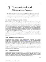
generate hydrogen. Materials concerns have recently caused the initial outlet tem-
perature goal for the U.S. design to be lowered to 900 to 950°C.
127
A schematic
diagram of a combined nuclear–steam electrolysis plant is shown in gure 2.4.
Process heat would be available for generating electricity and heating steam, after
heat exchanging of the helium coolant. The temperature of the steam available to
the electrolysis process will depend upon the heat exchanger efciencies and cer-
tainly will be signicantly lower than the latest proposed outlet temperature of 900
to 950°C. Some additional heat that would increase the cell temperature may be
derived from IR losses within the electrolysis cells. The high-temperature electrol-
ysis process will utilize both heat and electricity generated by the reactor. Another
VHTR design, the Pebble Bed Modular Reactor (PBMR), is being developed in
South Africa through a worldwide international collaborative effort led by South
Africa’s Electricity Supply Commission (ESKOM; supplies approximately 95% of
that country’s electricity). The PBMR currently has an average helium coolant exit
temperature of 900°C under normal operating conditions.
128
aCknoWledgmenTs
This work was supported by the U.S. Department of Energy’s Ofce of Nuclear
Energy Science and Technology, under DOE-NE Idaho Operations Ofce Con-
tract DE-AC07-05ID14517.
H
2
, H
2
O separator
H
2
O
H
2
O+H
2
H
2
O
H
2
O
2
Power for electrolysis
Power to grid
Make-up
water
High-
temperature
steam
electrolysis
unit
Heat
exchanger
He
He
High-
temperature
heat
exchanger
He
He
Recuperator
Primary
heat
rejection
He
HP
compressor
He
He
LP compressor
Intercooler
Gas
turbine
Electrical
generator
fIgure 2.4 High-temperature steam electrolysis to generate hydrogen using heat and
electricity from a high-temperature gas-cooled nuclear reactor.
5024.indb 53 11/18/07 5:45:10 PM
54 Materials for the Hydrogen Economy
referenCes
1. Wendt, H. and Imarisio, G., Nine years of research and development on advanced water
electrolysis. A review of the research programme of the Commission of the European
Communities,
J. Appl. Electrochem., 18, 1–14 (1988).
2. Wendt, H., Hofmann, H., and Plzak, V. Anode and cathode-activation, diaphragm-con
-
struction and electrolyzer conguration in advanced alkaline water electrolysis,
Int. J.
Hydrogen Energy, 9, 297–302 (1984).
3. Wendt, H., Hofmann, H., and Plzak, V., Materials research and development of electro
-
catalysts for alkaline water electrolysis,
Mater. Chem. Physics, 22, 27–49 (1989).
4. Ramesh, L. et al., Electrolytic preparation and characterization of Ni-Fe-Mo- alloys:
cathode materials for alkaline water electrolysis,
Int. J. Energy Res., 23, 919–924
(1999).
5. Hu, W., Electrocatalytic properties of new electrocatalysts for hydrogen evolution in
alkaline water electrolysis,
Int. J. Hydrogen Energy, 25, 111–118 (2000).
6. Suffredini, H.B. et al., Recent developments in electrode materials for water electroly
-
sis,
Int. J. Hydrogen Energy, 25, 415–423 (2000).
7. Abdel Ghany, N.A. et al., Oxygen evolution anodes composed of anodically deposited
Mn-Mo-Fe oxides for seawater electrolysis,
Electrochem. Acta, 48, 21–28 (2002).
8. Wendt, H. and Hofmann, H., Cermet diaphragms and integrated electrode-diaphragm
units for advanced alkaline water electrolysis,
Int. J. Hydrogen Energy, 10, 375–381
(1985).
9. Kreuter, W. and Hofmann, H., Electrolysis: the important energy transformer in a world
of sustainable energy,
Int. J. Hydrogen Energy, 23, 661–666 (1998).
10. Rasten, E., Hagen, G., and Tunold, R., Anode catalyst materials for PEM-electrolysis,
in
New Materials for Electrochemical Systems IV. Extended Abstracts of the Fourth
International Symposium on New Materials for Electrochemical Systems, Montreal,
Quebec, Canada, July 9–13, 2001, pp. 278–280.
11. Linkous, C.A. et al. Development of new proton exchange membrane electrolytes
for water electrolysis at higher temperatures,
Int. J. Hydrogen Energy, 23, 525–529
(1998).
12. Weikang, H. et al., A novel cathode for alkaline water electrolysis,
Int. J. Hydrogen
Energy, 22, 621–623 (1997).
13. Weikang, H., Electrocatalytic properties of new electrocatalysts for hydrogen evolution
in alkaline water electrolysis,
Int. J. Hydrogen Energy, 25, 111–118 (2000).
14. Oi, T. and Sakaki, Y., Optimum hydrogen generation capacity and current density of
the PEM-type water electrolyzer operating only during the off-peak period of electric
-
ity demand,
J. Power Sources, 129, 229–237 (2004).
15. Morizonoa, T., Watanabe, K., and Ohstsuka, K., Production of hydrogen by electrolysis
with proton exchange membrane (PEM) using sea water and fundamental study of
hybrid system with PV-ED-FC,
Mem. Fac. Eng., 31, 213–218 (2002).
16. HOGEN
Hydrogen Generators from Proton Energy Systems, 50 Inwood Rd., Rocky
Hill, CT 06067, 860-571-6533, www.protonenergy.com.
17. Friedland, R.J. and Speranza, A.J., Hydrogen Production through Electrolysis, paper
presented at the Proceedings of the 2001 DOE Hydrogen Program Review, NREL/CP-
570-30535, Golden, CO, June 4-5, 2001.
18. Hamilton Sundstrand (A United Technologies Company), One Hamilton Rd., Windsor
Locks, CT 06096, 860-654-6000.
19. Treadwell Corp., 341 Railroad St., Thomaston, CT 06787, 860-283-8251.
20. Hydrogenics Corp., 5985 McLaughlin Rd., Mississauga, Ontario, Canada, L5R 1 B8,
905-361-3660.
5024.indb 54 11/18/07 5:45:11 PM
Materials for Water Electrolysis Cells 55
21. Giner Electrochemical Systems, LLC, 89 Rumford Ave., Newton, MA 02466,
781-529-0500.
22. Stucki, S. et al., PEM water electrolysers: evidence for membrane failure in 100 kW
demonstration plants,
J. Appl. Electrochem., 28, 1041–1049 (1998).
23. Ando, U. and Tanaka, T., Proposal for a new system for simultaneous production of
hydrogen and hydrogen peroxide by water electrolysis,
Int. J. Hydrogen Energy, 29,
11349–11354 (2004).
24. Foster, R. and Wright, R.L. Jr.,
Basic Nuclear Engineering, Boston, MA: A. Allyn and
Bacon, 1968.
25. Nogami, M., Matsushita, H., Kasuga, T., and Hayakawa, T., Hydrogen gas sensing by
sol-gel-derived proton-conducting glass membranes,
Electrochem. Solid-State Lett., 2,
415–417 (1999).
26. Kuo, C.K., Tan, A., Sarkar, P., and Nicholson, P.S., Water partial pressure-dependent
conductance and humidity effects on hydronium-
β"-Al
2
O
3
ceramics, Solid State Ionics,
58, 311–314 (1992).
27. Schafer, G., Zyl, A.V., and Weppner, W., Process for the Production of K- or Rb-
β"- or
-β-Aluminum Oxide Ion Conductors, U.S. Patent 5,474,959, December 12, 1995.
28. Schafer, G.W., Kim, H.J., and Aldinger, F., Protonated
β"-aluminas, correlation of ion-
exchange rates, chemical composition and resulting lattice constants,
Solid State Ion-
ics, 97, 285–289 (1997).
29. Joshi, A.V., Liu, M., Bjorseth, A., and Renberg, L., NaOH Production from Ceramic
Electrolytic Cell, U.S. Patent 5,290,405, March 1, 1994.
30. Damasceno, O., Siebert, E., Khireddine, H., and Fabry, P., Ionic exchange and selectiv
-
ity of NASICON sensitive membranes,
Sensors Actuators B, 8, 245–248 (1992).
31. Slade, R.C.T. and Young, K.E., Hydronium and ammonium NASICONs: investigations
of conductivity and conduction mechanism,
Solid State Ionics, 46, 83–88 (1991).
32. “PRONAS” available from Ceramatec, Inc., 2425 South 900 West, Salt Lake City, UT
84119, 801-978-2152.
33. Farrington, G.C. and Briant, J.L., Fast ionic transport in solids,
Science, 204, 1371–
1379 (1979).
34. McGeehin, P. and Hooper, A., Fast ion conduction materials [review],
J. Mater. Sci., 12,
1–27 (1977).
35. Mizuno, M. and Hayashi, S., Proton dynamics in phase II of CsHSO
4
studied by H-1
NMR,
Solid State Ionics, 167, 317–323 (2004).
36. Kaminura, H. et al., On the mechanism of superionic conduction in the zero-dimen
-
sional hydrogen-bonded crystals M
3
H(XO
4
)
2
; (M = K, Rb, Cs, and X = S, Se), Physica
Status Solidi C, 1, 8 (2004).
37. Park, J H., Possible origin of the proton conduction mechanism of CsH
2
PO
4
crystals at
high temperatures,
Phys. Rev. B, 69, 54104-1-6 (2004).
38. Yaroslavtsev, A.B. and Kotov, V.Y., Proton mobility in hydrates of inorganic acids and
acid salts,
Russ. Chem. Bull., 54, 555–568 (2002).
39. Wu, Q.Y. and Meng, G.Y., Preparation and conductibility of solid high-proton conduc
-
tor molybdovana dogermanic heteropoly acid,
Mater. Res. Bull., 35, 85–91 (2000).
40. Adams, S., CDW superstructures in hydrogen molybdenum bronzes HxMoO
3
, J. Solid
State Chem., 149, 75–87 (2000).
41. U.S. Department of Energy,
A Technology Roadmap for Generation IV Nuclear Energy
Systems, GIF-002-00, Nuclear Energy Research Advisory Committee and the Genera-
tion IV International Forum, December 2002.
42. Guan, J. et al., Ceramic oxygen generators with thin-lm zirconia electrolytes,
J. Am.
Ceram. Soc., 85, 2651–2654 (2002).
43. Rambert, S. et al., Composite ceramic fuel cell fabricated by vacuum plasma spraying,
J. Eur. Ceram. Soc., 19, 921–923 (1999).
5024.indb 55 11/18/07 5:45:12 PM
56 Materials for the Hydrogen Economy
44. Henne, R.H. et al., Light-Weight SOFCs for Automotive Auxiliary Power Units, paper
presented at the 2nd International Conference on Fuel Cell Science, Engineering and
Technology, Rochester, NY, June 14–16, 2004.
45. Wang, L.S. et al., Sputter deposition of yttria-stabilized zirconia and silver cermet elec
-
trodes for SOFC applications,
Solid State Ionics, 52, 261–267 (1992).
46. Chu, W.F., Thin- and thick-lm solid ionic devices,
Solid State Ionics, 52, 243–248
(1992).
47. Windes, W.E. and Lessing, P.A., Plasma spray coatings for SOFC, in
2002 Fuel Cell
Seminar Abstracts, Courtesy Associates, Washington, DC, 471–474, 2002.
48. Chen, T.Y. and Fung, K.Z., A and B-site substitution of the solid electrolyte LaGaO
3
and LaAlO
3
with the alkaline-earth oxides MgO and SrO, J. Alloys Compounds, 368,
106–115 (2004).
49. Kurumada, M., Ito, A., and Fujie, Y., Preparation of
La2-x
Sr
x
Ga
0.8
Mg
0.2
O
3-δ
electrolyte
for solid oxide fuel cell by citrate method using industrial raw materials,
J. Ceram. Soc.
Jpn., 111, 200–204 (2003).
50. Choi, S.M., et al., Oxygen ion conductivity and cell performance of La
0.9
Ba
0.1
Ga
1–
x
Mg
x
O
3-δ
electrolyte, Solid State Ionics, 131, 221–228 (2000).
51. Kharton, V.V. et al., Ionic and p-type electronic conduction in LaGa(Mg,Nb)O
3-δ
perovksites,
Solid State Ionics, 128, 79–90 (2000).
52. Maffei, N. and de Silveira, G., Interfacial layers in tape cast anoe-supported doped
lanthanum gallate SOFC elements,
Solid State Ionics, 159, 209–216 (2003).
53. Kim, J.H. and Yoo, H.I., Partial electronic conductivity and electrolytic domain of
La
0.9
Sr
0.1
Ga
0.8
Mg
0.2
O
3-δ
, Solid State Ionics, 140, 105–113 (2001).
54. Zhang, X.G. et al., Interactions of La
0.9
Sf
0.1
Ga
0.8
Mg
0.2
O
3-δ
electrolyte with Fe
2
O
3
, Co
2
O
3
and NiO anode materials,
Solid State Ionics, 139, 145–152 (2001).
55. Majkic, G. et al., High-temperature deformation of La
0.2
Sr
0.8
Fe
0.8
Cr
0.2
O
3-δ
mixed ionic-
electronic conductor,
Solid State Ionics, 146, 393–404 (2002).
56. Kostogloudis, G.C. et al., Chemical compatibility of alternative perovskite oxide SOFC
cathodes with doped lanthanum gallate solid electrolyte,
Solid State Ionics, 134, 127–
138 (2000).
57. Zhang, X.G. et al., Interface reactions in the NiO-SDC-LSGM system,
Solid State Ion-
ics, 133, 153–160 (2000).
58. Wang, S.Z., High performance fuel cells based on LaGaO
3
electrolytes, Acta Physico-
Chim. Sin., 20, 43–46 (2004).
59. Kuroda, K. et al., Characterization of solid oxide fuel cell using doped lanthanum gal
-
late,
Solid State Ionics, 132, 199–208 (2000).
60. Ma, X. et al., The power of plasma,
Ceramic Industry, June 2004, pp. 25–28.
61. Pengnian, H. et al., Interfacial reaction between nickel oxide and lanthanum gallate
during sintering and its effect on conductivity,
J. Am. Ceram. Soc., 82, 2402–2406
(1999).
62. Maffei, N. and de Silveira, G., Interfacial layers in tape cast anode-supported doped
lanthanum gallate SOFC elements,
Solid State Ionics, 159, 209–216 (2003).
63. Huang, K.G. et al., Increasing power density of LSGM-based solid oxide fuel cells
using new anode materials, J
. Electrochem. Soc., 148, A788–A794 (2001).
64. Wang, S.Z. and Tatsumi, I., Improvement of the performance of fuel cells anodes with
Sm
+3
doped CeO
2
, Acta Physico-Chim. Sin., 19, 844–848 (2003).
65. Huang, K.Q. et al., Electrode performance test on single ceramic fuel cells using as
electrolyte Sr- and Mg-doped LaGaO
3
, J. Electrochem. Soc., 144, 3620–3624 (1997).
66. Elangovan, S., Hartvigsen, J.J., O’Brien, J.E., Stoots, C.E., Herring, J.S., and Lessing,
P.A., Operation and Analysis of Solid Oxide Fuel Cells in Steam Electrolysis Mode,
paper presented at Session B07, 6th European SOFC Forum, Lucerne, Switzerland,
June 28–July 2, 2004.
5024.indb 56 11/18/07 5:45:13 PM
Materials for Water Electrolysis Cells 57
67. Ishihara, T. et al., Oxide ion conductivity in doubly doped PrGaO
3
perovskite-type
oxide,
J. Electrochem. Soc., 146, 1643–1649 (1999).
68. Maricle, D.L. et al., Enhanced ceria: a low-temperature SOFC electrolyte,
Solid State
Ionics, 52, 173–182 (1992).
69. Kharton, V.V. et al., Ceria-based materials for solid oxide fuel cells,
J. Mater. Sci., 36,
1105–1117 (2001).
70. Hidenori, Y. et al., High temperature fuel cell with ceria-yttria solid electrolyte,
J.
Electrochem. Soc. Solid-State Sci. Technol., 2077–2080 (1988).
71. Kirk, T.J. and Winnick, J., A hydrogen sulde solid-oxide fuel cell using ceria-based
electrolytes,
J. Electrochem. Soc., 140, 3494–3496 (1993).
72. Lu, C. et al., SOFCs for direct oxidation of hydrocarbon fuels with samaria-doped ceria
electrolyte,
J. Electrochem. Soc., 150, A354–A358 (2003).
73. Alfa Aesar 2004 catalog prices: La
2
O
3
(99.99%) $108/kg, Ga
2
O
3
(99.999%) $3400/kg,
CeO
2
(99.9%) $84/kg, Y
2
O
3
(99.99%) $212/kg, Gd
2
O
3
(99.99%) $320/kg.
74. Azad, A.M., Larose, S., and Akbar, S.A., Review bismuth oxide-based solid electro
-
lytes for fuel cells,
J. Mater. Sci., 29, 4135–4151 (1994).
75. Fung, K.Z. et al., Massive transformation in the Y
2
O
e
-Bi
2
O
3
system, J. Am. Ceram.
Soc., 77, 1638–1648 (1994).
76. Fung, K.Z. et al., Thermodynamic and kinetic considerations for Bi
2
O
3
-based electro-
lytes,
Solid State Ionics, 52, 199–211 (1992).
77. Joshi, A.V. et al., Phase stability and oxygen transport characteristics of yttria- and
niobia-stabilized bismuth oxide,
J. Mater. Sci., 25, 1237–1245 (1990).
78. Abraham, F. et al., The BIMEVOX series: a new family of high performance oxide ion
conductors,
Solid State Ionics Diffusion React., 40/41, 934–937 (1990).
79. Simner, S.P. et al., Synthesis, densication, and conductivity characteristics of BICU
-
VOX oxygen-ion-conducting ceramics,
J. Am. Ceram. Soc., 80, 2563–2568 (1997).
80. Yaremchenko, A.A. et al., Physicochemical and transport properties of Bicuvox-based
ceramics,
J. Electroceram., 4, 233–242 (2000).
81. Pasciak, G. et al., Solid electrolytes for gas sensors and fuel cells applications,
J. Eur.
Ceram. Soc., 21, 1867–1870 (2001).
82. Priovano, C. et al., Characterisation of the electrode-electrolyte BIMEVOX system for
oxygen separation. Part I. In situ synchrotron study,
Solid State Ionics, 159, 167–179
(2003).
83. Kharton, V.V. et al., Ceria-based materials for solid oxide fuel cells,
J. Mater. Sci., 36,
1105–1117 (2001).
84. Setoguchi, T. et al., Effects of anode materials and fuel on anodic reaction of solid
oxide fuel-cells,
J. Electrochem. Soc., 139, 2875–2880 (1993).
85. Jiang, S.P. and Chan, S.H., A review of anode materials development in solid oxide fuel
cells,
J. Mater. Sci., 39, 4405–4439 (2004).
86. Hartvigsen, J., Elangovan, S., and Khandkar, A., A Comparison of Proton and Oxy
-
gen Ion Conducting Electrolytes for Fuel Cell Applications, paper presented at AIChE
Annual Meeting Fuel Cells for Utility Applications and Transportation: Engineering &
Design II, St. Louis, MO, November 11, 1993.
87. Iwahara, H. et al., High temperature type proton conductor based on SrCeO
3
and its
application to solid electrolyte fuel cells,
Solid State Ionics, 9/10, 1021–1026 (1983).
88. Iwahara, H., High temperature-type proton conductive solid oxide fuel cells using vari
-
ous fuels,
J. Appl. Electrochem., 16, 663–668 (1986).
89. Iwahara, H., Oxide-ionic and protonic conductors based on perovskite-type oxides and
their possible applications,
Solid State Ionics, 52, 99–104 (1992).
90. Iwahara, H. et al., Proton conduction in sintered oxides based on BaCeO
3
, J. Electro-
chem. Soc. Solid-State Sci. Technol., 135, 529–533 (1988).
5024.indb 57 11/18/07 5:45:14 PM
58 Materials for the Hydrogen Economy
91. Chen, F.L. et al., Preparation of Nd-doped BaCeO
3
proton-conducting ceramic and
its electrical properties in different atmospheres,
J. Eur. Ceram. Soc., 18, 1389–1395
(1998).
92. Bhide, S.V. and Virkar, A.V., Stability of BaCeO
3
-based proton conductors in water-
containing atmospheres,
J. Electrochem. Soc., 146, 2038–2044 (1999).
93. Kreuer, K.D., Aspects of the formation and mobility of protonic charge carriers
and the stability of perovskite-type oxides,
Solid State Ionics, 125, 285–302 (1999).
94. Kreuer, K.D. et al., Proton conducting alkaline earth zirconates and titanates for high
drain electrochemical applications,
Solid State Ionics, 145, 295–306 (2001).
95. Kreuer, K.D., Proton-conducting oxides,
Annu. Rev. Mater. Res., 33, 333–359 (2003).
96. Hassan, D. et al., Proton-conducting ceramics as electrode/electrolyte materials for
SOFC’s. Part I. Preparation, mechanical and thermal properties of sintered bodies,
J.
Eur. Ceram. Soc., 23, 221–228 (2003).
97. Fehringer, G. et al., Proton-conducting ceramics as electrode/electrolyte: materials
for SOFCs: preparation, mechanical and thermal-mechanical properties of thermal
sprayed coatings, material combination and stacks,
J. Eur. Ceram. Soc., 24, 705–715
(2004).
98. Kreuer, K.D., Proton-conducting oxides,
Annu. Rev. Mater. Res., 33, 333–359 (2003).
99. Kobayashi, T. et al., Study on current efciency of steam electrolysis using a partial
protonic conductor SrZr
0.9
Yb
0.1
O
3-δ
, Solid State Ionics, 138, 243–251 (2001).
100. Jian, S.P. et al., A comparative investigation of chromium deposition at air electrodes
of solid oxide fuel cells,
J. Eur. Ceram. Soc., 22, 361–373 (2002).
101. Kofstad, P. and Bredesen, R., High temperature corrosion in SOFC environments,
Solid
State Ionics, 52, 69–75 (1992).
102. Yang, S.G. et al., Solid oxide fuel cells: materials for the bipolar plates are under devel
-
opment to reduce costs while maintaining performance and durability,
Adv. Mater.
Processes, 161, 34 (2003).
103. Larring, Y. and Norby, T., Spinel and perovskite functional layers between Plansee
metallic interconnect (Cr-5 wt% Fe-1 wt% Y
2
O
3
) in ceramic (La
0.85
Sr
0.15
)
0.91
MnO
3
cath-
ode materials for solid oxide fuel cells,
J. Electrochem. Soc., 147, 3251–3256 (2000).
104. Kung, S.C. et al., Performance of Metallic Interconnect in Solid-Oxide Fuel Cells,
paper presented at the 2000 Fuel Cell Seminar, Portland, OR, October 30–November
2, 2000.
105. Horita, T. et al., Evaluation of Fe-Cr alloys as interconnects for reduced operation tem
-
perature SOFCs,
J. Electrochem. Soc., 150, A243–A248 (2003).
106. Windes, W.E. and Lessing, P.A., Fabrication Methods of a Leaky SOFC Design, paper
presented at the Eighth International Symposium of Solid Oxide Fuel Cells (SOFC
VIII), 203rd Meeting of the Electrochemical Society, Paris, April 27–May 2, 2003.
107. Windes, W.E. and Lessing, P.A., A Low CTE Intermetallic Bipolar Plate, paper pre
-
sented at the Eighth International Symposium of Solid Oxide Fuel Cells (SOFC VIII),
203rd Meeting of the Electrochemical Society, Paris, April 27–May 2, 2003.
108. Hartvigsen, J.J. et al., Via Filled Interconnect for Solid Oxide Fuel Cells, U.S. Patent
6,183,897 B1, February 6, 2001.
109. Badding, M.E. et al., High Performance Solid Electrolyte Fuel Cells, U.S. Patent Appli
-
cation 20010044041, November 22, 2001.
110. Meulenberg, W.A. et al., Improved contacting by the use of silver in solid oxide fuel
cells up to an operating temperature of 800°C,
J. Mater. Sci., 36, 3189–3195 (2001).
111. Wang, L.S. et al., Sputter deposition of yttria-stabilized zirconia and silver cermet elec
-
trodes for SOFC applications,
Solid State Ionics, 52, 261–267 (1992).
112. Meulenberg, W.A. et al., Oxidation behaviour of ferrous alloys used as interconnecting
material in solid oxide fuel cells,
J. Mater. Sci., 38, 507–513 (2003).
5024.indb 58 11/18/07 5:45:14 PM
Materials for Water Electrolysis Cells 59
113. Subbarao, E. and Maiti, H.S., Solid electrolytes with oxygen ion conduction, Solid State
Ionics, 11, 317–338 (1984).
114. Kilner, J.A. and Brook, R.J., A study of oxygen ion conductivity in doped non-stoichio
-
metric oxides,
Solid State Ionics, 6, 237–252 (1982).
115. USGS, Year 2000 data: Sc
2
O
3
(99.99% pure) $3,000/kg, Sc
2
O
3
(99.9% pure) $700/kg;
Y
2
O
3
(99.99% pure) $ 200/kg.
116. The system Y
2
O
3
-Sc
2
O
3
-ZrO
2
: phase stability and ionic conductivity studies, J. Eur.
Ceram. Soc., 7, 197–206 (1991).
117. Singhal, S.C., Science and technology of solid-oxide fuel cells,
MRS Bull., 25, 16–21
(2000).
118. Anderson, H.U. and Nasrallah, M.M., Characterization of Oxide for Electrical Deliv
-
ery Systems, paper presented at the EPRI/GRI Fuel Cell Workshop on Fuel Cell Tech
-
nology Research and Development, New Orleans, April 13–14, 1993.
119. Misuyasu, H. et al., Microscopic analysis of lanthanum strontium manganite yttria-
stabilized zirconia interface,
Solid State Ionics, 100, 11–15 (1997).
120. Donitz, W. and Erdle, E., High-temperature electrolysis of water vapor: status of devel
-
opment and perspectives for application,
Int. J. Hydrogen Energy, 10, 291–295 (1985).
121. Hino, R. and Miyamoto, Y., Hydrogen production by high-temperature electrolysis of
steam, in
High Temperature Applications of Nuclear Energy, International Atomic
Energy Agency, 1994, pp. 119–124.
122. Herring, J.S., Anderson, R., Lessing, P.A., O’Brien, J.E., Stoots, C.M., Hartvigsen, J.J.,
and Elangovan, S., Hydrogen Production through High-Temperature Electrolysis in a
Solid Oxide Cell, paper presented at the National Hydrogen Association 15th Annual
Conference, Los Angeles, April 26–29, 2004.
123. O’Brien, J.E., Stoots, C.M., Herring, J.S., and Lessing, P.A., Characterization of Solid-
Oxide Electrolysis Cells for Hydrogen Production via High-Temperature Steam Elec
-
trolysis, Paper 2474, paper presented at the 2nd International Conference on Fuel Cell
Science, Engineering, and Technology, Rochester, NY, June 14–16, 2004.
124. Herring, J.S., O’Brien, J.E.,. Stoots, C.M,. Lessing, P.A, Anderson, R.P., Hartvigsen,
J.J., and Elangovan, S., Hydrogen Production from Nuclear Energy via High-Tempera
-
ture Electrolysis, Paper 4322, pape presented at the 2004 International Conference on
Advances in Nuclear Power Plants (ICAPP’04), Pittsburgh, PA, June 13–17, 2004.
125. Herring, J.S., O’Brien, J.E., Stoots, C.M., Lessing, P.A., Anderson, R.P., Hartvigsen,
J.J., and Elangovan, S., Hydrogen Production through High-Temperature Electrolysis
Using Nuclear Power, paper presented at the AIChE Spring National Meeting, New
Orleans, April 25–29, 2004.
126. Very High Temperature Reactor (VHTR) Survey of Materials Research and Develop
-
ment Needs to Support Early Deployment, INL/EXT-03-004-141, January 31, 2003.
127. Design Features and Technology Uncertainties for the Next Generation Nuclear Plant,
INEEL/EXT-04-01816, Independent Technology Review Group, June 30, 2004.
128. Ion, S. et al., Pebble Bed Modular Reactor: The First Generation IV Reactor to Be
Constructed, paper presented at the World Nuclear Association Annual Symposium,
London, September 3–5.
5024.indb 59 11/18/07 5:45:15 PM
5024.indb 60 11/18/07 5:45:15 PM