Materials for the Hydrogen Economy (2007) Episode 10 ppt
Bạn đang xem bản rút gọn của tài liệu. Xem và tải ngay bản đầy đủ của tài liệu tại đây (1.56 MB, 30 trang )
246 Materials for the Hydrogen Economy
5. William, M. C., Strakey, J. P., and Surdoval, W. A., Int. J. App. Ceram. Tech., 2, 295,
2005.
6. Paulick, S. W., Baskaran, S., and Armstrong, T. R.,
J. Mater. Sci., 33, 2397, 1998.
7. Peck, D-H., Miller, M., and Hilpert, K.,
Solid State Ionics, 143, 391, 2001.
8. Chick, L.A., Liu, J., Stevenson, J. W., Armstrong, T. R., McCready, D.E., Maupin,
G. D., Coffey, G. W., and Coyle, C. A.,
J. Am. Ceram. Soc., 80, 2109, 1997.
9. Fergus, J.W.
Solid State Ionics, 171, 1, 2004.
10. Anderson, H.C., and Tietz, F., in
High Temperature Solid Oxide Fuel Cells: Funda-
mentals, Design and Applications, Eds., S.S. Singhal and K. Kendall, 173, Oxford:
Elsevier. 2003.
11. de Souza, S., Visco, S.J., and De Jonghe, L.C.,
Solid State Ionics, 98, 57, 1997.
12. de Souza, S., Visco, S.J., and De Jonghe, L.C.,
J. Electrochem. Soc., 144, L35,
1997.
13. Ishihara, T., Matsuda, H., and Takita, Y.,
J. Am. Chem. Soc., 116, 3801, 1994.
14. Huang, Q., Tichy, R., and Goodenough, J. B.,
J. Am. Ceram. Soc., 81, 2565, 1998.
15. Quadakkers, W.J., Piron-Abellan, J., Shemet, V., and Singheiser, L.,
Mater. High
Temp., 20, 115, 2003.
16. Yang, Z., Weil, K.S., Paxton, D.M., and Stevenson, J.W.,
J. Electrochem. Soc., 150,
A1188, 2003.
17. Zhu, W.Z. and Deevi, S.C.,
Mater. Sci. & Eng., A348, 227, 2003.
18. Fergus, J.W.,
Mater. Sci. & Eng., A397, 271, 2005.
19. Sims, C.T., Stoloff, N.S., and Hagel, W.C.,
Superalloys II, New York: John Wiley &
Sons, 1987.
20. Davis, J.R.
ASM Specialty Handbook: Stainless Steels, Materials Park, OH: ASM
International®, 1994.
21. Wasielewski, G.E. and Robb, R.A.,
High Temperature Oxidation in The Superalloys,
Eds. C.S. Sims and W. Hagel, 287, New York: John Wiley & Sons, Inc., 1972.
22. Kofstad, P.
Nonstoichometry, Diffusion and Electrical Conductivity in Binary Metal
Oxides, Malabar, FL: Robert E. Krieger, 1983.
23. Kofstad, P. and Bredesen, R.,
Solid State Ionics, 52, 69, 1992.
24. Holt, A., and Kofstad, P.,
Solid State Ionics, 69, 137, 1994.
25. Holt, A. and Kofstad, P.,
Solid State Ionics, 69, 127, 1994.
26. Abeilan, J.P., Shemet, V., Tietz, F., Singheiser, L., and Quadakkers, W.J., in
SOFC VII-
Electrochemical Society Proceedings PV-2001-16, Eds., S.C. Singhal and M. Dokiya,
811, The Electrochemical Society, Pennington, NJ, 2001.
27. Teller, O., Meulenberg, W.A., Tietz, F., Wessel, E., and Quadakkers, W.J., in
SOFC
VII- Electrochemical Society Proceedings PV2001-16, Eds., S.C. Singhal and M.
Dokiya, 895, The Electrochemical Society, Pennington, NJ, 2001.
28. Quadakkers, W.J., Shemet, V., and Singheiser, L. U.S. Patent. 2003059335, 2003.
29. Quadakkers, W.J., Malkow, T., Piron-Abellan, J., Flesch, U., Shemet, V., and Sing
-
heiser, L., in
Proceedings of the 4
th
European SOFC Forum, Vol. 2, 827, European Fuel
Cell Forum, Switzerland, 2000.
30. Buchkremer, H.P., Diekmann, U., de Haart, L.G. J., Kabs, H., Stover, D., and Vinke,
I.C., in
Proceedings of the 3
rd
European SOFC Forum, Ed., P. Stevens, Vol. 1, 143,
European Fuel Cell Forum, Switzerland, 1998.
31. Yang, Z., Xia, G G., Walker, M.P., Wang, C M., Stevenson, J.W., and Singh, P.,
Inter. J. Hydrogen Energy, 2006, in press.
32. Yang, Z., Hardy, J.S., Walker, M.S., Xia, G., Simner, S.P., and Stevenson, J.W.,
J.
Electrochem. Soc., 151, A1825, 2004.
33. Park, J.H. and Natesan, K.
Oxid. Met., 33, 31, 1990.
34. Sasamoto, T., Sumi, N., Shimaji, A., Yamamoto, O., and Abe, Y.,
J. Mater. Sci. Soc., 33,
32, 1996.
5024.indb 246 11/18/07 5:54:22 PM
Corrosion and Protection of Metallic Interconnects 247
35. Fava, F.F., Barraille, I., Lichanot, A., Larrieu, C., and Dovesi, R., J. Phys. Condense
Mater., 9, 10715, 1997.
36. Lu, Z., Zhu, J., Payzant, E.A., and Paranthaman, M.P.,
J. Am. Ceram. Soc., 88, 1050,
2005.
37. Virkar, A.V. and England, D.M., U.S. Patent 6054231, 2000.
38. Horita, T., Xiong, Y., Yamaji, K., and Sakai, N.,
J. Electrochem. Soc., 150, A243,
2003.
39. Uehara, T. Ohno, T., and Toji, A., in
Proceedings of the 5
th
European SOFC Forum,
ed., J. Huijsmans, 281, European Fuel Cell Forum, Switzerland, 2002.
40. Quadakkers, W.J., Greiner, H., Kock, W., Buchkremer, H.P., Hilpert, K., and Stover,
D., in
Proceedings of the 2
nd
European SOFC Forum, Ed., B. Thorstensen, 297, Euro-
pean Fuel Cell Forum, Switzerland, 1996.
41. Kofstad, P.
High Temperature Corrosion, 2nd ed., London: Elsevier Applied Science,
1988.
42. Birks, N., Meier, G.H., and Pettit, F.S.,
Introduction to the High Temperature Oxidation
of Metals, 2nd ed., London: Cambridge University Press, 2006.
43. Young, D.J. and Watson, S.,
Oxid. Met., 44, 239, 1995.
44. Gesmundo, F. and Gleeson, B.,
Oxid. Met., 44, 211 1995.
45. F.H. Stott, G.C. Wood, and J. Stringer, Oxid. Met., 1995, 44, 113.
46. Linderoth, S., Hendriksen, P.V., Mogensen, M., and Langvad, N.,
J. Mater. Sci., 31,
5077, 1996.
47. England, D.M. and Virkar, A.V.,
J. Electrochem. Soc., 146, 3196, 1999.
48. Yang, Z., Xia, G G., Singh, P., and Stevenson, J.W.,
J. Power Sources, 160, 1104,
2006.
49. Geng, S.J., Zhu, J.H., and Lu, Z.G., Solid State Ionics, 177, 559, 2006.
50. Geng, S.J., Zhu, J.H., and Lu Z.G.,
Script. Mater, 55, 239, 2006.
51. Alman, D.E. and Jablonski, P.D. In
Fuel Cell Seminar, Washington, DC: Courtesy
Associate, 2004.
52. Kofstad, P. and Bredesen, R.,
Solid State Ionics, 52, 69, 1992.
53. Huang, K., Hou, P.Y., and Goodenough, J.B.,
Solid State Ionics, 129, 237, 2000.
54. England, D.M. and Virkar, A.V.,
J. Electrochem. Soc., 148, A330, 2001.
55. Holcomb, G.R. and Alman, D.E.,
J. Mater. Eng. & Perform., 2006, 15, 394.
56. Meulenberg, W.A., Uhlenbruck, S., Wessel, E., Buchkremer, H.P., and Stover, D., J.
Mater. Sci., 2003, 38, 507.
57. Brylewski, T., Nanko, M., Maruyama, T., and Przybylski, K., Solid State Ionics, 143,
131, 2001.
58. Geng, S.J., Zhu, J.H. and Lu, Z.G.,
Electrochem. & Solid-State Lett., 9, A211 2006.
59. Zeng, Z. and Natesan, K.,
Solid State Ionics, 167, 9, 2004.
60. Toh, C.H., Munroe, P.R., Young, D.J., and Foger, K.,
Mater. High Temp., 20, 129,
2003.
61. Horita, T., Xiong, Y., Kishimoto, H., Yamaji, K., Sakai, N., Brito, M.E., and Yoko
-
kawa, H.,
J. Electrochem. Soc., 152, A2193, 2005.
62. Horita, T., Xiong, Y., Kishimoto, H., Yamaji, K. Sakai, N., and Yokokawa, H.,
Surf.
Interface Anal., 36, 973, 2004.
63. Jian, L., Huezo, J., and Ivey, D.G., J. Power Sources, 123, 151, 2003.
64. Yang, Z., Walker, M.S., Singh, P., and Stevenson, J.W
., Electrochem. & Solid State
Lett., 6, B35, 2003.
65. Yang
, Z., Walker, M.S., Singh, P., Stevenson, J.W., and Norby, T., J. Electrochem.
Soc., 151, B669, 2004.
66. Sing, P., Yang, Z., Viswanathan, V, and Stevenson, J.W.,
J. Mater. Perform. Eng., 13,
287, 2004.
5024.indb 247 11/18/07 5:54:23 PM
248 Materials for the Hydrogen Economy
67. Yang, Z., Xia, G-G., Singh, P., and Stevenson, J.W., Solid State Ionics, 176, 1495,
2005.
68. Ziomek-Moroz, M., Cramer, S.D., Holcomb, G.R., Covino, B.S., Jr, Bullard, S.J., and
Singh, P., in
Corrosion, NACE International, Houston, TX, 2005, paper 10.
69. Holcomb, G.R., Ziomek-Moroz, M., Cramer, S.D., Covino, B.S., Jr., and Bullard, S.J.,
J. Mater. Eng. & Perform., 15, 404, 2006.
70. Kurokawa, H., Kawamura, K., and Maruyama, T.,
Solid State Ionics, 168, 13, 2004.
71. Quadakkers, W.J., Hansel, M., and Rieck, T.,
Mater. & Corro., 49, 252, 1999.
72. Larring, Y., Hangsrud, R., and Norby, T.,
J. Electrochem. Soc., 150, B374, 2003.
73. Bongartz, K., Quadakkers, W.J., Pfeifer, J.P., and Becker, J.S.,
Surf. Sci., 292, 196,
1993.
74. Rapp, R.A.,
Metall. Trans. A, 15A, 765, 1984.
75. Huczkowski, P., Shemet, V., Piron-Abellan, J., Singheiser, L., Quadakkers, W. J., and
Christiansen, N.,
Mater. & Corrosion, 55, 825, 2004.
76. Huczkowski, P., Ertl, S., Piron-Abellan, J., Christiansena, N., Ho, T., Shemet, V., Sing
-
heiser, L., and Quadakkers, W.J.,
Mater. High Temp., 22, 253, 2005.
77. Huczkowski, P., Christiansen, N., Shemet, V., Piron-Abellan, J., Singheiser, L., and
Quadakkers, W. J.,
J. Fuel Cell Sci. & Tech., 1, 30, 2004.
78. Hou, P. and Stringer, J.,
Oxid. Met., 38, 323, 1992.
79. Golightly, F., Stott, H., and Wood, G.,
Oxid. Met., 10, 163, 1976.
80. Pint, B.,
Oxid. Met., 45, 1, 1996.
81. Pieraggi, B. and Rapp, R.A.,
J. Electrochem. Soc., 140, 2844, 1993.
82. Kofstad, P.,
Oxid. Met., 44, 3, 1995.
83. Douglass, D.L., Kofstad, P., Rahmel, A., and Wood, G.C.,
Oxid. Met., 45, 529, 1996.
84. Kvernes, I., Oliveira, M., and Kofstad, P.,
Corrosion Sci., 17, 237, 1977.
85. Shen, J., Zhou, L., and Li, T.,
Oxid. Met., 38, 347, 1997.
86. Pint, B.A.,
J. Eng. Gas Turbine and Power, 128, 370, 2006.
87. Fujii, C.T. and Meussner, R.A.,
Corro. Iron & Steel, 111, 1215, 1964.
88. Lefrancois, P.A. and Hoyt, W.B.,
Corrosion, 19, 360, 1963.
89. Grabke, H.J., Muller-Lorenz, E.M., Eltester, B., and Lucas, M.,
Mater. High Temp., 17, 339, 2000.
90. Toh, C.H., Munroe, P.R., and Young, D.J.,
Mater. High Temp., 20, 527, 2003.
91. Hochman, R.F., in
Proceedings of the 4th International Congress Metal Corrosion,
Ed., N.E. Hammer, NACE, 258, 1972.
92. Grabke, H.J., Bracho-Troconis, C.B., and Muller-Lorenz, E.M.,
Werkstoffe und Korrosion, 45, 215, 1994.
93. Zeng, Z. and Natesan, K.,
Chem. Mater., 15, 872, 2003.
94. Schneider, R., Pippel, E., Woltersdorf, J., Strauss, S., and Grabke, H.J.,
Steel Research,
68, 326, 1997.
95. Nakagawa, K., Matsunaga, Y., and Yanagisawa, T.,
Mater. High Temp., 20, 67, 2003.
96. Meier, G. H.,
2005 Proceedings of the U.S. DOE SECA Core Technology Peer Review,
National Energy Technology Laboratory, pro
-
ceedings/05/SECA_PeerReview/SECAPeerReview05.html.
97. Singh, P., Paetsch, L., and Maru, H.C., in Corrosion 86/87, NACE, Houston, TX,
2006, paper 86.
98. Nakagawa, K., Matsunaga, Y., and Yanagisawa, T.,
Mater. High Temp., 18, 51, 2001.
99. Wood, G.C., Wright, I.G., Hodgkiess, T., and Whittle, D.P.,
Werkst Korros, 21, 900,
1970.
100. Yang, Z., Xia, G G., Singh, P., and Stevenson, J.W.,
J. Electrochem. Soc., 153, A1873,
2006.
101. Kurokawa, H., Oyama, Y., Kawamura, K., and Maruyama, T.,
J. Electrochem. Soc.,
151, A1264, 2004.
5024.indb 248 11/18/07 5:54:24 PM
Corrosion and Protection of Metallic Interconnects 249
102. Eichler, K., Solow, G., Otschik, P., and Schafferath, W., J. Europ. Ceram. Soc., 19,
1101, 1999.
103. Meinhardt, K.D., Vienna, J.D., Armstrong, T.R., and Peterson, L.R., U.S. patent
6430966, 2001.
104. Sohn, S.B., Choi, S.Y., Kim, G. H., Song, H.S., and Kim, G.D., J. Non-Cryst. Solids,
297, 103, 2002.
105. Schwickert, T., Geasee, P., Janke, A., Diekmann, U., and Conradt, R., in Proceedings of
the International Brazing and Soldering Conference, 116, Albuquerque, NM, 2000.
106. Sohn, S B., Choi, S Y., Kim, G H., Song, H S., and Kim, G D.,
J. Amer. Ceram.
Soc., 87, 254, 2004.
107. Yang, Z., Meinhardt, K.D., and Stevenson, J.W.,
J. Electrochem. Soc., 150, A1095,
2003.
108. Yang, Z., Stevenson, J.W., and Meinhardt, K.D.,
Solid State Ionics, 160, 213, 2003.
109. Yang, Z., Xia, G G., Meihardt, K.D., Weil, K.S., and Stevenson, J.W.,
J. Mater. Eng. &
Perform., 13, 327, 2004.
110. Pistorius, C.W.F.T. and Pistorius, M.C.,
Z. Krist, 117, 259, 1962.
111. Haanapel, V.A.C., Shemet, V., Vinke, I.C., and Quadakkers, W.J.,
J. Power Sources,
141, 102, 2005.
112. Haanapel, V.A.C., Shemet, V., Vinke, I.C., Gross, S.M., Koppitz, Th., Menzler, N.H.,
Zahid, M., and Quadakkers, W.J.,
J. Mater. Sci., 2005, 40, 1583.
113. Haanapel, V.A.C., Shemet, I.C., Gross, S.M., Koppitz, Th., Menzler, N.H., Zahid, M.,
and Quadakkers, W.J.,
J. Power Sources, 2005, 150, 86.
114. Batfalsky, P., Haanapel, V.A.C., Malzbender, J., Menzler, N.H., Shemet, V., Vinke, I.C.,
and Steinbrech, R.W.,
J. Power Sources, 2005, 155, 128.
115. Yang, Z., Xia, G G., Singh, P., and Stevensoin, J.W.,
J. Power Sources, 155, 246,
2006.
116. Badwal, S. P. S., Deller, R., Foger, K., Ramprakash, Y., and Zhang, J. P., Solid State
Ionics, 99, 297, 1997.
117. Quadakkers, W.J., Greiner, H., Hansel, M., Pattanaik, A., Khanna, A.S. and Mallener,
W.,
Solid State Ionics, 91, 55, 1996.
118. Maruyama, T., Inoue, T., and Nagata, K., in
SOFC VII-Electrochemical Society Pro-
ceedings PV-2001-16, Ed., S.C. Singhal and M. Dokiya, Editors, 889, The Electro-
chemical Society, ennington, NJ, 2001.
119. Arul Raj, I., Tietz, F., Gupta, A., Jungen, W., and Stover, D.,
Acta Mater., 49, 1987,
2001.
120. Tietz, F., Arul Raj, I., Jungen, W., and Stover, D.
Acta Mater., 49, 803, 2001.
121. Yang, Z., Coyle, C.A., Baskaran, S., and Chick, L.A., U.S. Patent 6843406, 2005.
122. Linderoth, S.,
Surf. & Coating Tech., 80, 185, 1996.
123. Sakai, N., Yamaji, K., Horita, T., Lshikawa, M., Yokokawa, H. and Dokiya, M., in
Pro-
ceedings of the 3
rd
European SOFC Forum, Ed., P. Stevens, 333, European Fuel Cell
Forum, Switzerland, 1993.
124. Kadowaki, T., Shiomitsu, T., Matsuda, E., Nakagawa, H., and Tsuneisumi, H.,
Solid
State Ionics, 67, 65, 1993.
125. Batawi, E., Honegger, K., Diethelm, D., and Wettstein, M. in
Proceedings of the 2nd
European SOFC Forum, Ed., B. Tharstensen, 307, European Fuel Cell Forum, Swit-
zerland, 1996.
126. Fujita, K., Ogasawara, K., Matsuzaki, Y., and Sakurai, T.,
J. Power Sources, 131, 261,
2004.
127. Hilpert, K. Das, D., Miller, M., Peck, D.P., and Weib, R.,
J. Electrochem. Soc., 143,
3642, 1996.
128. Jacobson, N., Myers, D., Opila, E., and Copland, E.,
J. Phys. Chem. Sol., 66, 471,
2005.
5024.indb 249 11/18/07 5:54:25 PM
250 Materials for the Hydrogen Economy
129. Yang, Z., Xia, G G., Maupin, G.D., and Stevenson, J.W.,
J. Electrochem. Soc., 153,
A1852, 2006.
130. Qu, W., Jian, L., Hill, J.M., and Ivey, D.G.,
J. Power Sources, 153, 114, 2006.
131. Larring, Y. and Norby, T.,
J. Electrochem., Soc., 147, 3251, 2000.
132. Yang, Z., Xia, G., and Stevenson, J.W.,
Electrochem. & Solid State Lett., 8 A168,
2005.
133. Yang, Z., Xia, G G., Simner, S.P., and Stevenson, J.W.,
J. Electrochem. Soc., 152,
A1896, 2005.
134. Yang, Z., Xia, G G., Li, X H., and Stevenson, J.W.,
Int. J. Hydrogen Energy, 2006 in
press.
135. Chen, X., Hou, P.Y., Jacobson, C.P., Visco, S.J., and De Jonghe, L.C.,
Solid State Ionics,
176, 425, 2005.
136. Yang, Z., Xia, G-G., Maupin, G., Simner, S., Li, X., Stevenson, J., and Singh, P. In Fuel
Cell Seminar, paper 253, 2006, Courtesy Associate, Washington.
137. Yokoyama, T., Abe, Y., Meguro, T., Komeya, K., Kondo, K. Kaneko, S., and Sasamoto,
T.,
Japan J. Appl. Phys., 35, 5775, 1996.
138. Yang, Z., Li, X H., Maupin, G.D., Singh, P., Simner, S.P., Stevenson, J.W., Xia, G G.,
and Zhao, X D.,
Ceram. Sci. & Eng. Proc., 27, 231, 2006.
139. Ling, H. and Petric, A., in SOFC IX-Electrochem. Soc. Proc. PV2005-07, ed., S.C.
Singhal and J. Mizusaki, 1866, The Electrochemical Society, Pennington, NJ, 2005.
140. Simner, S.P., Anderson, M.D., Xia, G G., Yang, Z., and Stevenson,
J.W., Ceram. Eng.
& Sci. Proc., 26, 83, 2005.
5024.indb 250 11/18/07 5:54:26 PM
251
12
Materials for Proton
Exchange Membrane
Fuel Cells
Bin Du, Qunhui Guo, Zhigang Qi,
Leng Mao, Richard Pollard, and John F. Elter
CONTENTS
12.1 Introduction 252
12.2 Electrode Materials 254
12.2.1 Anode Catalyst Materials 256
12.2.1.1 Pt-Loading Reduction 257
12.2.1.2 Non-Pt Anode Catalysts 258
12.2.1.3 Carbon Monoxide–Tolerant Anode Catalysts 259
12.2.2 Cathode Catalyst Materials 262
12.2.2.1 Pt and Pt Alloy Cathode Catalysts 263
12.2.2.2 Non-Pt Cathode Catalysts 265
12.2.2.3 Stability of Pt Cathode Catalysts 266
12.2.3 Electrode Support Materials 267
12.2.3.1 Stability of Carbon Support 268
12.2.3.2 Modied Carbon and Noncarbon Support Materials 270
12.2.3.3 Other Components of Electrode Layers 271
12.2.4 Engineered Nanostructured Electrodes 272
12.3 Membrane Electrolyte Materials 274
12.3.1 Peruorosulfonic Acid Membrane Materials 274
12.3.1.1 Thin Reinforced Membrane for Improved Mechanical
Properties 275
12.3.1.2 Improvement in PFSA Chemical Stability through
End-Group Modication 277
12.3.1.3 Modication of PFSA Membrane 279
12.3.2 Polybenzimidazole Membrane Materials 280
12.3.3 Current Status of Hydrocarbon Membranes 281
12.3.3.1 Styrene 282
12.3.3.2 Poly(Arylene Ether) 282
12.3.3.3 Polyimide Membranes 284
12.3.3.4 Arkema PVDF Membranes 284
12.3.3.5 Polyphosphazene Membranes 284
12.4 Gas Diffusion Layer Materials 285
5024.indb 251 11/18/07 5:54:27 PM
252 Materials for the Hydrogen Economy
12.5 Bipolar Plate Materials 286
12.6 Materials Compatibility and Manufacturing Variables 289
12.6.1 Sealing Materials and Coolant Compatibility
290
12.6.2 Coolant and Bipolar Plate Compatibility
290
12.6.3 Other Component Compatibility Issues
291
12.6.4 Component Manufacturing Variables and System Reliability
291
12.7 Summary 292
Acknowledgments 293
References 293
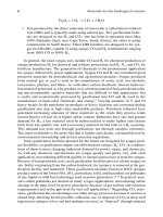
12.1 INTRODUCTION
Proton exchange membrane (PEM) fuel cell technology is a promising alternative
for a secure and clean energy source in portable, stationary, and automotive appli
-
cations. However, it has to compete in cost, reliability, and energy efciency with
established energy sources such as batteries and internal combustion engines. Many
of the major challenges in PEM fuel cell commercialization are closely related to
three critical materials considerations: cost, durability, and performance. The chal
-
lenge is to nd a combination of materials that will give an acceptable result for the
three criteria combined. For example, Hamilton Standard (a subsidiary of United
Technologies Corporation) demonstrated individual cell lifetimes of over 87,600 run
hours on at least three individual test cells operated continuously at 0.54 A/cm
2
using a thick membrane (Naon
®
120, 250 m thick) and Pt black electrodes (>10
mg Pt/cm
2
).
1,2
They also achieved stable voltage (decay rate ~ 1 V/h) for 40,000 h
on a four-cell stack operated continuously at low current density (CD) (~0.13 A/cm
2
).
These lifetime performances met or exceeded the Department of Energy (DOE)
target (40,000 h) for stationary applications.
3
However, the cost of these systems is
prohibitively high for commercial applications (DOE targets: $30/kW for transporta
-
tion applications using neat H
2
and $750/kW for stationary power applications using
natural gas reformate). On the other hand, state-of-the-art PEM fuel cells, using
thinner membranes (<40 m) and Pt/C electrodes (<1 mg Pt/cm
2
) for cost reduction,
are less expensive (but still higher than DOE cost targets) but only have a demon
-
strated lifetime of less than 15,000 h operating on reformate.
3–5
There are numerous
reviews on general PEM fuel cell technology,
5–11
fuel cell components,
12–15
electrode
catalysts,
16–24
membrane electrolytes,
25–32
bipolar plates,
33,34
and system reliability
and compatibility.
4,35,36
This chapter summarizes the current status of materials-
related aspects of PEM fuel cell research and development, including basic func
-
tional requirements, state-of-the-art materials, and technical challenges for each
individual component. Hydrogen production, distribution, and storage are covered
in sections 12.1 to 12.3.
The idea of using an ion-conductive polymeric membrane as a gas–electron bar
-
rier in a fuel cell was rst conceived by William T. Grubb, Jr. (General Electric
Company) in 1955.
37,38
In his classic patent,
37
Grubb described the use of Amber-
plex C-1, a cation exchange polymer membrane from Rohm and Haas, to build a
prototype H
2
–air PEM fuel cell (known in those days as a solid-polymer electrolyte
fuel cell). Today, the most widely used membrane electrolyte is DuPont’s Naon
5024.indb 252 11/18/07 5:54:28 PM
Materials for Proton Exchange Membrane Fuel Cells 253
due to its good chemical and mechanical stability in the challenging PEM fuel cell
environment. A peruorinated polymer with pendant sulfonated side chains, Naon
was initially developed in 1968 by Walther G. Grot of DuPont for the chlor-alkali
cell project of the National Aeronautics and Space Administration (NASA) space
program.
39
Several manufacturers provide other peruorinated polymers, composite
polymers, and hydrocarbon polymers as membrane electrolytes.
25–32
Figure 12.1 is a schematic view of a typical PEM fuel cell. A membrane elec-
trode assembly (MEA) usually refers to a ve-layer structure that includes an anode
gas diffusion layer (GDL), an anode electrode layer, a membrane electrolyte, a cath
-
ode electrode layer, and a cathode GDL. Most recently, several MEA manufacturers
started to include a set of membrane subgaskets as a part of their MEA packages.
This is often referred to as a seven-layer MEA. In addition to acting as a gas and
e
-
H
2
O
2
H
2
O
Fuel
inlet
Air
inlet
H
+
e
-
e
-
Anode
outlet
Cathode
outlet
Bipolar
Plate
Bipolar
Plate
Subgasket Subgasket
Catalyzed
Membrane
Gas Diffusion Layers
FIGURE 12.1 Schematic views of a PEM fuel cell and a seven-layered MEA.
5024.indb 253 11/18/07 5:54:30 PM
254 Materials for the Hydrogen Economy
electron barrier, a membrane electrolyte transports protons (H
+
) from the anode,
where H
2
is oxidized to produce H
+
ions and electrons, to the cathode, where H
+
ions and electrons recombine with O
2
to produce H
2
O. Small organic molecules,
such as CH
3
OH and HCOOH, can also be used as the anode fuel in place of H
2
, but
they pose special challenges for various MEA components, especially the catalysts
(poisoning) and the membrane (swelling and fuel crossover). For economic reasons,
air is usually used as the cathode feed rather than pure O
2
. Electrons are carried
from the anode to the cathode through the external electric circuit. The anode and
cathode electrode layers are typically made of Pt or Pt alloys dispersed on a car
-
bon support for maximum catalyst utilization. Ionomers and polytetrauoroethylene
(PTFE) resins can be added to the electrode layers. The former extends the proton
transport path beyond the electrode–membrane interfaces; the latter facilitates liquid
water removal from the electrode layers. Both can also help bind together various
electrode components. GDLs are made of porous media such as carbon paper or
carbon cloth to facilitate the transport of gaseous reactants to the electrode layers, as
well as the transport of electrons and water away from the electrode layers. An MEA
is sandwiched between two bipolar plates to form a single fuel cell. The word
bipo-
lar refers to a plate’s bipolar nature in a series of single cells (known as a stack) in
which a plate (or a set of half plates) is anodic on one side and cathodic on the other
side. Bipolar (half) plates often have gas channels on the side facing an MEA and
channels for temperature control on the other side and, together with the GDLs, they
provide structural support for the MEAs in addition to serving as transport media for
reactants/products, electricity, and heat.
In the following sections, a brief overview of the basic electrochemical pro
-
cesses in a H
2
/O
2
PEM fuel cell is given, followed by information on individual fuel
cell components: anode, cathode, catalyst support, membrane, GDLs, and bipolar
plates. The focus is on the specic functionalities and material requirements for
each individual component. The subgaskets of a seven-layer MEA will be discussed
in conjunction with materials compatibility in a separate section, which also covers
the materials selection criteria for coolant, hoses, and other system components. A
high-temperature (HT) version of the H
2
/O
2
PEM fuel cell using a polybenzimid-
azole–phosphoric acid (PBI-PA) membrane electrolyte will also be described, with
emphasis on its advantages and disadvantages relative to low-temperature (LT)
counterparts. Other types of PEM fuel cells using small organic molecules as direct
fuels, such as direct methanol fuel cells (DMFCs), are beyond the scope of this book
and will be discussed only when relevant to a H
2
/O
2
PEM fuel cell system.
12.2 ELECTRODE MATERIALS
The hydrogen oxidation reaction (HOR) occurs at the anode electrode of an H/O
2
PEM fuel cell (reaction 1):
H
2
↔ 2 H
+
+ 2 e
–
E
0
= 0 V (1)
This is a thermodynamically reversible process that often serves as a standard
reference electrode, known as the reversible hydrogen electrode (RHE), for all other
electrochemical processes.
5024.indb 254 11/18/07 5:54:30 PM
Materials for Proton Exchange Membrane Fuel Cells 255
At the cathode electrode, the thermodynamically irreversible four-electron oxy-
gen reduction reaction (ORR) is the dominant electrochemical process (reaction 2):
O
2
+ 4 H
+
+ 4 e
–
↔ 2 H
2
O E
0
= 1.229 V (2)
When connected through an external circuit, the net result of these two half-cell
reactions is the production of H
2
O and electricity from H
2
and O
2
. Heat is also gen-
erated in the process. In the absence of a proper catalyst, however, neither of these
two half reactions takes place at meaningful rates under PEM fuel cell operating
conditions (50 to 80°C, 1 to 5 atm). Despite decades of effort in search of cheaper
alternatives, platinum is still the catalyst of choice for both the HOR and ORR.
In a real fuel cell, the apparent cell voltage is signicantly lower than 1.229
V, the standard potential difference between the two half reactions. The difference
between the ideal and apparent cell voltage is known as the overpotential, which
includes catalyst activation loss, mass transport loss, and ohmic loss (gure 12.2).
Most of the activation losses originate from a sluggish ORR kinetics,
40
as the overpo-
tential for the HOR on a Pt anode is generally negligible except at a very high CD or
in the presence of certain catalyst-poisoning species (such as CO). These overpoten
-
tials are responsible for the reduced efciency of an electrochemical cell. For an HT
system, some of the energy lost may be recuperated through a heat recovery process
for internal or external usage, but the quality of the heat from an LT system may be
too low for this to be worthwhile.
Hydrogen peroxide is also formed as the two-electron ORR-byproduct (reaction 3):
O
2
+ 2 H
+
+ 2 e
–
↔ H
2
O
2
E
0
= 0.695 V (3)
Current Density (A/cm
2
)
Cell Voltage (V)
Ideal Cell Voltage: 1.229 V
Activation Loss
Mass Transport Los s
Ohmic Loss
Total Overpotential Loss
Apparent Cell VoltageApparent Cell Voltage
FIGURE 12.2 Schematic view of various overpotential losses: ideal and apparent fuel cell
voltage–current characteristics.
5024.indb 255 11/18/07 5:54:32 PM
256 Materials for the Hydrogen Economy
The free radicals (·OH, ·OOH, …) from H
2
O
2
decomposition are a primary cause of
membrane and ionomer chemical degradation.
25
The H
2
O
2
-related membrane degra-
dation mechanism will be discussed in more detail in section 12.3.1. The remainder
of section 12.2 is divided into four subtopics: anode, cathode, catalyst support, and
engineered nanostructured electrodes.
12.2.1 anOde CatalySt materialS
As mentioned above, an anode serves as the HOR site in a H
2
/O
2
fuel cell. As such,
it must fulll the following basic functional requirements: (1) transport H
2
to the
catalyst sites, (2) catalyze the HOR process, (3) carry protons away from the reac
-
tion sites to the membrane electrolyte, (4) remove electrons from the anode, and (5)
transfer heat in or out of the reaction zone. Water management is also an important
consideration, as it is for all PEM fuel cell components.
The HOR process is believed to proceed through the following steps (Reactions
4 to 6; M = metal catalyst):
41,42
H
2
+ 2 M → 2 MH
ads
Tafel reaction (4)
or
H
2
+ H
2
O + M → MH
ads
+ H
3
O
+
+ e
–
Heyrovsky reaction (5)
and
MH
ads
+ H
2
O → H
3
O
+
+ e
–
+ M Volmer reaction (6)
The rate-determining step varies depending on the specic catalysts and the
reaction conditions. For a PEM fuel cell with a Pt anode, the HOR process involves
only the Tafel and Volmer reactions, with the Tafel reaction being the rate-determin
-
ing step.
41
The rate of the overall HOR process can be expressed in the Butler–Vol-
mer form (equation 12.1):
j j e e
F RT F RT
s s
= −
−
( )
[ ]
0
1
1 1
β η β η
/ /
(12.1)
The exchange current density (
j
0
) depends on the nature of the catalyst mor-
phology, the catalyst–electrolyte interface, the properties of the reaction media (pH,
electrolyte, temperature, concentration, etc.), and the levels of contaminants such
as CO, Cl
–
, and sulfur species. For the HOR, the measurement of j
0
is further com-
plicated by the lowered H
2
gas diffusivity in a strong electrolyte solution known as
the “salting out” effect.
42
As a result, the reported value ranges from 10
–5
to 10
–2
A/
cm
2
for different Pt electrodes in various acidic media.
42
However, the rate-limiting
process of a H
2
/O
2
fuel cell is the ORR on the cathode electrode because j
0
for the
ORR is 10
–6
~ 10
–11
A/cm
2
.
40
Anode materials research has been centered mostly on
Pt-loading reduction, CO-tolerant catalysts for DMFCs and systems operating with
CO-contaminated fuels (such as reformate), and low-cost Pt alternatives.
5024.indb 256 11/18/07 5:54:33 PM
Materials for Proton Exchange Membrane Fuel Cells 257
12.2.1.1 Pt-Loading Reduction
Over the last 15 years or so, reduction of Pt loading has been accomplished primar
-
ily through the transition from Pt black catalysts (~10 mg Pt/cm
2
used in the NASA
space program) to high surface area carbon-supported Pt catalysts (nominally 0.8 mg
Pt/cm
2
for representative commercial MEAs).
6,7,43,44
It has been estimated that at j
0
=
27 mA/cm
2
, an anode with 0.05 mg Pt/cm
2
loading would be sufcient to support the
HOR up to 1 A/cm
2
with less than 10 mV overpotential loss (gure 12.3).
44
Johnson
Matthey reported the half-cell test results of an anode catalyst with as low as 0.025
mg Pt/cm
2
(20% Pt on Vulcan
®
XC72R) and observed less than a 5-mV increase in
anode overpotential.
23
An MEA with a PtRu
20
/C anode catalyst provided by Adzic’s
group at Brookhaven National Laboratory (anode, 0.022 mg Pt/cm
2
; cathode, com-
mercial Pt/C catalyst-coated GDL with 0.4 mg Pt/cm
2
) demonstrated a 10- to 15-mV
improvement over a commercial anode (1:1 alloy, 0.6 mg Pt/Ru/cm
2
) when 100% H
2
was used as the fuel.
45–47
The PtRu
20
/C anode catalyst was prepared by depositing
a monolayer of Pt over approximately 1/8 of the surface of carbon-supported Ru
nanoparticles through the spontaneous deposition of Pt on Ru.
48–50
The metallic Ru
surface undergoes facile oxidation without dissolution, which ensures selective Pt
deposition on Ru but not at the carbon support. Long-term (>1,000 h) performance
evaluation of this anode catalyst, by both Plug Power and Los Alamos National
Laboratory (~0.017 mg Pt/cm
2
), demonstrated excellent cell voltage stability using
neat H
2
as the fuel.
45–47
However, this catalyst appeared to be highly susceptible to
Ru oxidation and quickly lost its CO tolerance when operating with a CO-containing
reformate.
45
Zeis et al. prepared Pt-plated nanoporous gold leafs as low Pt loading
(10 to 100 g Pt/cm
2
) and carbon-free electrodes.
51
The long-term stability of low Pt
FIGURE 12.3 Calculated anode overpotential as a function of current density and Pt load-
ing. (From Gasteiger, H. A. et al., J. Power Sources, 127, 162, 2004. With permission.)
5024.indb 257 11/18/07 5:54:35 PM
258 Materials for the Hydrogen Economy
loading electrodes is still not settled, and more experiments are needed using either
neat H
2
or reformate.
23,44–47
12.2.1.2 Non-Pt Anode Catalysts
As mentioned earlier, the rate-determining step in the HOR process for a H
2
/O
2
PEM fuel cell is the Tafel reaction.
41
It involves the dissociative chemisorption of H
2
on a catalyst surface to form MH adatom species. Figure 12.4 is a volcano diagram
depicting the hydrogen evolution reaction (HER, a thermodynamically reversible
process of the HOR) exchange current density over different metal surfaces as a
function of the calculated hydrogen chemisorption energy.
52
There is a clear cor-
relation between hydrogen chemisorption energy and exchange current density. Pt is
a better HOR catalyst than other metals because the Tafel reaction is energetically
neutral on Pt at the equilibrium potential.
52
A few other metals, such as Pd and Re,
also possess HOR exchange current densities that are comparable to that of a Pt
electrode. However, chemical instability limits the application of these elements as
viable anode catalysts under PEM fuel cell operating conditions. Furthermore, the
cost of Pd or Re, although considerably lower than that of Pt, would still be high for
a commercial fuel cell.
6E
H
/(eV)
6G
H
/(eV)
-0.64 -0.44 -0.24 -0.04 -0.16
Log(io/(A cm
-2
))
-1
-2
-3
-4
-5
-6
-7
-2
-3
-4
-5
-6
-7
-8
-0.4 -0.2
0
0.2 0.4
Nb
Mo
W
Co
Ni
Re
Pd
Rh
Pi
lr
Cu
Au
Ag
FIGURE 12.4 Top: Experimentally measured exchange current, log(i
0
), for the HER over
different metal surfaces plotted as a function of the calculated hydrogen chemisorption
energy per atom, ΔE
H
(top axis). Single crystal data are indicated by open symbols. Bottom:
The result of the simple kinetic model plotted as a function of the free energy for hydrogen
adsorption, ΔG
H*
= ΔE
H
+ 0.24 eV. (From Nørskov, J. K. et al., J. Electrochem. Soc., 152, J23,
2005. With permission.)
5024.indb 258 11/18/07 5:54:38 PM
Materials for Proton Exchange Membrane Fuel Cells 259
Nonprecious metal alloys, carbides, or oxides may hold the solution to the
cost and chemical instability problems. WC
x
and WO
x
are the most studied sys-
tems as low-cost alternatives to a Pt anode because of their excellent stability in
acidic media. They also have high CO tolerance because CO does not readily
adsorb onto their surfaces.
53–56
WC
x
is particularly attractive because its electron
density states near the Fermi level are similar to those of Pt.
57,58
Yang and Wang
obtained a high CD (0.9 A/cm
2
) from a H
2
–air PEM fuel cell with a WC anode
(0.48 mg WC/cm
2
).
59
The CD was limited by the WC anode in contrast to a typi-
cal PEM fuel cell with a Pt anode, which is cathode (ORR) limited and can reach
over 2 A/cm
2
under the same test conditions. Nevertheless, this represents a CD
increase of two orders of magnitude over the previously reported WC anode
catalysts.
60,61
Limoges et al. looked at the HOR catalytic activities of a series of heteropolyac-
ids (HPAs) containing Mo and V.
62
The CD is too low (a few mA/cm
2
) for them to be
used as stand-alone anode catalysts, although it should be pointed out that the HPA
loading of the anode used in this study was one to two orders of magnitude lower on
a molar basis than that of a typical Pt anode. However, HPAs have been shown to be
promising proton-conductive membrane/ionomer llers and effective catalysts for
H
2
O
2
decomposition.
63,64
On this basis, they may eventually become a part of fuel
cell electrodes.
12.2.1.3 Carbon Monoxide–Tolerant Anode Catalysts
The current lack of a national hydrogen infrastructure dictates that on-site hydrogen
generation will be the choice of many H
2
–air PEM fuel cell applications in the fore-
seeable future. In many respects, water hydrolysis using electricity generated through
renewable solar or wind energy would be ideal for on-site H
2
generation. However,
the most technically and economically viable on-site H
2
generation technology today
is still reforming of natural gas or other readily available hydrocarbon fuels. The
ubiquitous CO in a reformate fuel poses a signicant challenge to anode materi
-
als because even a few ppm of CO can induce a considerable cell voltage loss (g
-
ure 12.5).
65
This is because the Pt-CO adlayer formation is far more exothermic than
the energetically neutral Pt-H adatom formation.
50,66,67
The Pt-CO adlayer coverage
can reach over 98% even when just a few ppm of CO is present in a reformate.
23
In
this situation, the HOR can occur at only a few bare Pt sites in a compact CO mono
-
layer.
68
The result is an elevated anode overpotential even at a CD as low as 0.1 A/cm
2
(~0.8 V for an E-TEK 20% Pt/Vulcan
®
anode) and, in turn, a lower cell voltage.
69
Development of CO-tolerant anode materials is also driven by DMFC applica-
tions in which CO is one of the methanol oxidation products.
6,7
CO poisoning at the
DMFC anode leads to low power density, a critical parameter for portable applica
-
tions. Pt/Ru alloys are the state-of-the-art materials for CO-tolerant anodes. The
optimal Pt/Ru molar ratio is generally found to be 1:1, but it varies depending on the
exact nature of a Pt/Ru alloy and its fabrication process.
23,70
Pt alloys of other metals
(such as W, Sn, and Mo) and non-Pt alloys have also been examined as CO-tolerant
anode materials.
14,23,71
5024.indb 259 11/18/07 5:54:39 PM
260 Materials for the Hydrogen Economy
The generally accepted bifunctional mechanism for Pt/Ru-catalyzed CO oxi-
dation involves the formation of either a Ru-activated H
2
O molecule or a Ru(OH)
surface complex adjacent to Pt-CO sites (reactions 7 to 10):
72–74
Ru + H
2
O → Ru-H
2
O (7)
Ru-H
2
O + Pt-CO → CO
2
+ 2 H
+
+ 2 e
–
(8)
or
Ru + H
2
O → Ru(OH) + H
+
+ e
–
(9)
Ru(OH) + Pt-CO
→ CO
2
+ H
+
+ e
–
(10)
There appears to be a close link between the actual CO oxidation mechanism
and the nature of Pt-CO bonds: the route involving Ru-H
2
O is associated with a
CO molecule bridge bonded to two adjacent Pt sites,
72
whereas the route involving
Ru(OH) is linked to a CO molecule linearly bonded to a single Pt site.
73
For reformate with a high CO concentration (>10 ppm), a PEM fuel cell with a
Pt/Ru alloy anode still suffers from a substantial cell voltage loss, especially in the
high-CD region, because the maximum CO oxidation current occurs from 0.39 to
0.6 V.
75
At its onset potential (<0.1 V), the CO oxidation current density of a Pt/Ru
anode is capable of oxidizing only a few ppm CO. The ignition potential, dened as
the potential at which the CD increases by approximately two orders of magnitude
H
2
10 ppm CO in H
2
40 ppm CO in H
2
100 ppm CO in H
2
Solid
Pt
Dashed
PtRu
200 200 600 800 1000 1200
1.2
1.0
0.8
0.6
0.4
0.2
CELL POTENTIAL, V
CURRENT DENSITY, mA cm
-2
FIGURE 12.5 Progressive poisoning from 10, 40, and 100 ppm CO on pure Pt and Pt
0.5
Ru
0.5
alloy anodes. Increased CO tolerance is shown by the Pt
0.5
Ru
0.5
alloy anodes. The MEAs
are based on catalyzed substrates bonded to Naon 115. The single cell is operated at 80ºC,
308/308 kPa, 1.3/2 stoichiometry with full internal membrane humidication. (From Ralph,
T. R. and Hogarth, M. P., Platinum Metal Rev., 46, 117, 2002. With permission.)
5024.indb 260 11/18/07 5:54:41 PM
Materials for Proton Exchange Membrane Fuel Cells 261
within a narrow potential range, was found to be as high as 0.45 V in some cases.
76
A Pt/Ru anode may experience an overpotential from 0.39 V for a state-of-the-art
Pt/Ru catalyst to as high as 0.6 V for an average Pt/Ru catalyst when the Pt surface
is saturated with CO.
68–76
Gottesfeld and Pafford discovered that CO could be chemi-
cally oxidized to CO
2
when a small amount of air was bled into the anode of a PEM
fuel cell.
77,78
This CO oxidation process is electrochemically promoted and is cata-
lyzed by Pt.
79,80
Unlike the electrochemical CO oxidation catalyzed by Pt/Ru, the air
bleed (AB) process prefers a hydrophobic environment for facile O
2
diffusion. Excess
O
2
, usually at O
2
/CO > 100 (or 200 in stoichiometry), is required for effective CO
removal.
75
The excess O
2
reacts with H
2
. In addition to the consumption of valuable
H
2
, it also leads to the formation of a signicant amount of H
2
O
2
at the anode.
81–84
Free radicals (HO·, HOO·) generated by decomposition of H
2
O
2
have been identied
as the primary cause for ionomer/membrane chemical degradation.
29,85,86
We have
developed a pulsed air bleed (PAB) technology to minimize H
2
O
2
formation, and
hence to reduce the rate of membrane/ionomer degradation.
75
For a reformate with
10 ppm CO, PAB reduced the amount of air needed by more than 80% relative to a
continuous AB under otherwise the same operating conditions. This led to a reduc
-
tion in uoride release rate (FRR) of >70%, and it improved cell performance in
single-cell and short-stack endurance tests.
75,87
PAB is also a simple yet effective CO
mitigation strategy for systems with variable CO concentrations or transient high CO
concentrations because it automatically adjusts its pulsing frequency in response to
changes in CO concentration.
An anode conguration closely related to the AB approach is the so-called
recongured anode, in which a thin layer of metal (such as Pt/C) or metal oxide
(such as FeO
x
) is added to the outside of the anode GDL facing the ow eld.
79,88
Unlike a normal anode electrode layer that is impregnated with ionomers for facile
proton transport, this ionomer-free CO oxidation layer is hydrophobic for improved
gas diffusion to help maximize the interaction between CO and O
2
.
With almost endless possible combinations, nding the right alloy catalysts for
the HOR and CO-tolerant anode, and for that matter good ORR catalysts, requires
rational design strategies with a set of sound guidelines. Strasser et al. employed a
density functional theory (DFT) calculation to map out detailed adsorption energies
and activation barriers for a variety of model ternary PtRuM alloys as potential CO-
tolerant catalysts.
89
They found a similar trend for electrocatalytic activity as a func-
tion of the alloy composition as observed experimentally. Greeley and Mavrikakis
suggested the use of a plot of CO binding energy vs. surface segregation energy to
assist the selection of near-surface alloys (NSAs) as candidates for further screening.
90
NSAs are alloys where a solute metal is present near the surface of a host metal in
concentrations different from the bulk. A minute amount of solute metal in the sur
-
face region can drastically change the catalytic properties of the corresponding pure
metals.
90–92
At the NSA dilution limit, it is expected that defect sites on or near the sur-
face can catalyze the HOR by providing a local environment that resists poisoning.
90
High-throughput sample preparation and fast screening technology are essential for a
successful implementation of such a vast undertaking.
89,93
One attractive fast screen-
ing method was demonstrated by Stevens et al., who devised a 64-electrode PEM fuel
5024.indb 261 11/18/07 5:54:42 PM
262 Materials for the Hydrogen Economy
cell to study the effect of composition for a series of (Pt
1–x
Ru
x
)
1–y
Mo
y
alloys in a single
experimental run under realistic fuel cell operating conditions.
94
The equilibrium CO coverage on Pt decreases as the temperature increases
because CO adsorption on Pt is an exothermic process. It has been demonstrated in
phosphoric acid fuel cells that at temperatures above 180°C, one can operate with
a reformate containing 1% CO or higher.
6,7
The ability to operate with high CO
concentrations can greatly simplify the reforming subsystem for reduced cost and
improved system reliability. Plug Power has been working on a PBI-based PEM fuel
cell system with an operating temperature range from 160 to 180°C.
95
Compared
to its LT counterpart, this system eliminates the need for LT shift and preferential
oxidation (PROX) reactors in the fuel processing system. It also does not require
water management components for its fuel cell system. Furthermore, it enables a
combined heat and power (CHP) system design that provides high-quality heating
and improved system efciency. A Pt/C anode is used in place of a Pt/Ru alloy
because of the enhanced CO tolerance and the good chemical stability of Pt at the
elevated temperature.
12.2.2 CathOde CatalySt materialS
A cathode serves as the site for the ORR in a H
2
/O
2
fuel cell. It should fulll the fol-
lowing basic functional requirements: (1) transport O
2
to the catalyst sites, (2) carry
protons from the membrane electrolyte to the catalyst sites, (3) move electrons to the
reaction sites, (4) catalyze the ORR, (5) remove product water, and (6) transfer heat
to or from the reaction zone.
The exact ORR mechanism is still a topic of much debate.
40
Two representative
mechanisms, namely, a dissociative mechanism (reactions 11, 15, and 16) and an
associative mechanism (reactions 12 to 16), are illustrated here:
1/2 O
2
+ M → M-O
ads
(11)
or
O
2
+ M → M-O
2
(12)
M-O
2
+ H
+
+ e
–
→ M-O
2
H (13)
M-O
2
H + H
+
+ e
–
→ H
2
O + M-O
ads
(14)
The nal two steps are the same for both mechanisms:
M-O
ads
+ H
+
+ e
–
→ M-OH (15)
M-OH + H
+
+ e
–
→ H
2
O + M (16)
Recent studies pointed to the formation of a peroxy intermediate on the Pt
surface, suggesting that the more complex associative mechanism is at work on a
Pt electrode.
96–98
However, the DFT calculations by Nørskov et al. suggested that
the associative mechanism was only the dominant pathway at ORR overpotentials
greater than 0.8 V.
99
At realistic ORR overpotentials (<0.8 V), the two pathways run
5024.indb 262 11/18/07 5:54:43 PM
Materials for Proton Exchange Membrane Fuel Cells 263
parallel to each other. Regardless of the actual ORR mechanism, one thing is clear:
the ORR is the rate-limiting process in a H
2
/O
2
fuel cell. The slow ORR kinetics is
responsible for the steep slope in the activation polarization region (gure 12.2). A
small but noticeable H
2
crossover current at the open circuit (OC) is largely to blame
for the open-circuit voltage (OCV) loss even for a state-of-the-art membrane electro
-
lyte. Much of the cathode research has been directed at nding a cathode catalyst to
improve the slow ORR kinetics and to nd a cheap replacement for Pt.
12.2.2.1 Pt and Pt Alloy Cathode Catalysts
Pt and Pt alloys are the most active catalysts for the ORR.
100
The DFT calculations
by Nørskov et al. indicated that the ORR activity is a function of both the O and OH
binding energy.
99
They generated two ORR volcano plots (gure 12.6) for the ORR
activities of various metals: one based on the O binding energy (dissociative mecha
-
nism) and the other on both the O and OH binding energies (associative mechanism).
These plots explain why Pt is the best elemental catalyst material and why certain
Pt alloys display a better ORR activity than elemental Pt, i.e., metals such as Ni, Co,
Fe, and Cr have smaller O binding energies than Pt.
99
Markovic and Ross observed
that Pt alloys of Ni, Co, or Fe with a Pt monolayer on their surfaces displayed higher
ORR activities than the corresponding Pt alloys (skin effect).
96
Calculations by
Kitchin et al. indicated that the oxygen dissociative adsorption energy on the surface
Pt was weakened as its
d-band was broadened and lowered in energy by interactions
with the underlayer 3
d metals.
101
This explains the enhanced ORR activities of these
“skin” alloys. Studies like these have provided guidelines in the search for an effec
-
tive ORR catalyst. Adzic et al. synthesized a series of PtM (M = Ni, Co, Cr, Pd, Au,
Ru, Ir, Rh) alloy cathode catalysts.
46,48–50,102
These alloys exhibited better ORR activ-
ity than pure Pt, with the highest half-wave potential increase (45 mV) obtained on
a Pt/PtCo skin alloy.
102
Stamenkovic et al. demonstrated that the Pt
3
Ni(111)
surface
is 10 times more active for the ORR than the corresponding
Pt(111) surface, and
90 times more active than the current state-of-the-art
Pt/C catalysts for PEM fuel
cells.
103
Xu et al. studied the skin effect of Pt-Co and Pt-Fe alloys.
104
Teliska et al.
found that the OH chemisorption decreased
in the direction of Pt > Pt-Ni > Pt-Co >
Pt-Fe > Pt-Cr, which correlated directly with the
observed fuel cell performance.
105
Balbuena et al. developed a thermodynamic design guideline for bimetallic Pt alloy
ORR catalysts.
106,107
Tamizhmani and Capuano showed that Pt-Cr-Cu
1–x
(CuO)
x>0.3
was six times more active than pure Pt, and that Pt-Cr and Pt-Cr-Cu alloys were
about twice as active as Pt.
108
Mukerjee et al. studied the effect of alloy preparation
conditions on electronic and structural properties, and ORR electrocatalytic activi
-
ties.
109
Pt alloys can be made by either depositing a base metal onto pre-made Pt
particles or depositing Pt and base metals simultaneously. A sintering step at about
600°C or higher temperatures is often needed for the formation of a true alloy, which
may inadvertently cause the sintering and coalescence of alloy particles. Pt alloys of
other precious metals have also been shown to display higher ORR activities than
Pt alone. For example, Ioroi and Yasuda showed that Pt alloys with 5 to 20 wt% Ir
enhanced the ORR activity by a factor of more than 1.5 at 0.8 V.
110
5024.indb 263 11/18/07 5:54:44 PM
264 Materials for the Hydrogen Economy
FIGURE 12.6 Trends in ORR activity as a function of (a) the O binding energy and (b) both
the O and OH binding energy. (From Norskov, J. K. et al., J. Phys. Chem. B, 108, 17886, 2004.
With permission.)
5024.indb 264 11/18/07 5:54:46 PM
Materials for Proton Exchange Membrane Fuel Cells 265
The stability and durability of Pt alloys, especially those involving a 3d transi-
tion metal, are the major hurdles preventing them from commercial fuel cell appli
-
cations.
111,112
The transition metals in these alloys are not thermodynamically stable
and may leach out in the acidic PEM fuel cell environment. Transition metal atoms
at the surface of the alloy particles leach out faster than those under the surface of
Pt atom layers.
113
The metal cations of the leaching products can replace the pro-
tons of ionomers in the membrane and lead to reduced ionic conductivity, which in
turn increases the resistance loss and activation overpotential loss.
16
Gasteiger et al.
showed that preleached Pt alloys displayed improved chemical stability and reduced
ORR overpotential loss (in the mass transport region), but their long-term stability
has not been demonstrated.
16,114
These alloys experienced rapid activity loss after a
few hundred hours of fuel cell tests, which was attributed to changes in their surface
composition and structure.
114
Bouwman et al. demonstrated that Pt can be used in the ionic form (Pt
2+
and Pt
4+
)
by dispersing it in a matrix of hydrous iron phosphate (FePO) via a sol-gel process
(Pt-FePO).
115
The hydrous FePO possesses micropores of approximately 2 nm. It
has ~3 H
2
O molecules per Fe atom and is thought to also serve as a proton transport
medium. The Pt-FePO catalyst exhibited a higher ORR activity than Pt/C catalysts.
This catalyst was also found to be less sensitive to CO poisoning because CO did
not adsorb onto the catalyst surface. The ORR catalytic activity was attributed to the
adsorption and storage of oxygen on the FePO, presumably as Fe–hydroperoxides.
However, these catalysts have poor electrical conductivity. There is no published
data on the long-term stability of these catalysts in fuel cell environments.
12.2.2.2 Non-Pt Cathode Catalysts
There are many active programs pursuing nonprecious metal ORR catalysts, but
none of them have demonstrated acceptable ORR activity for practical usage.
17
The
most promising candidates are a class of Fe– and Co-N
x
–C complexes on a carbon
support that show reasonably good ORR activity.
17,116,117
Fe/Co-based PEM fuel cell
catalysts are often made by pyrolyzing metal porphyrins and other macrocycles.
The chelating reagents often contain four N atoms coordinated to the metal center
(N
4
-M). In 1964, Jasinski discovered that some N
4
–Co macrocycles were capable of
catalyzing the ORR.
118
Since then, a host of N
4
-M (M = Fe, Co) macrocycles have
been prepared and studied for PEM fuel cell applications.
119–128
The common chelat-
ing reagents are tetraazaannulene, phthalocyanine, and tetraphenylporphyrin. The
last two are porphyrin derivatives closely related to the heme unit found in biological
systems such as heme oxygenase, a common enzyme catalyzing the ORR process
in living organisms.
129
It was proposed that the catalytic site is the N
4
-M macro-
cycle bound to the carbon support through a heat treatment.
130,131
N
4
-M was shown to
improve not only the activity of these catalysts for the ORR, but also their chemical
stability, even in an acidic medium.
116
A second active site was recently identied
as Fe-N
2
/C based on its typical FeN
2
C
4
+
ion signature in time-of-ight secondary
ion mass spectometry, although its full coordination is not yet known.
131
There is
evidence that this Fe-N
2
/C site is catalytically more active than Fe-N
4
/C for oxygen
reduction, converting >95% oxygen to water.
131
Most recently, Bashyam and Zelenay
5024.indb 265 11/18/07 5:54:46 PM
266 Materials for the Hydrogen Economy
found that Co–polypyrrole–carbon exhibited a good ORR activity and a remarkable
stability with a Co loading as low as 0.06 mg/cm
2
in PEM fuel cells.
132
N
4
-M catalysts can also be made from nonmacrocyclic precursors.
133–138
In the
presence of a nitrogen source, they can be prepared by pyrolyzing transition metal
salts or complexes adsorbed on a carbon support. Examples of salts/complexes
include acetate,
127,139
Fe(OH)
2
(derived from FeSO
4
),
134
and phenanthroline com-
plexes.
137
The nitrogen sources may come from an external supply such as NH
3
,
139
or
from nitrogen surface groups of a N-enriched carbon support.
127,139
There are, however, many hurdles for transition metal-based catalysts to be used
in PEM fuel cells. The two critical ones are the low catalytic activity relative to
commercial Pt catalysts and the signicant peroxide generation as a side reaction.
The low catalytic activity is attributed to a low surface nitrogen content of the car
-
bon support, which is required to anchor metal atoms to the carbon.
127
Even with a
N-enriched carbon support, the best catalyst was reported to have a catalyst activity
of ~0.1 A/cm
2
at 0.6 V,
127
compared to >0.6 A/cm
2
for commercial Pt catalysts. The
signicant peroxide generation presents two major problems for PEM fuel cells: (1)
Naon membrane degradation as a result of peroxide free radical attack
29
and (2)
Fe/Co dissolution in acidic conditions catalyzed by peroxide.
131
Transition metal dis-
solution further accelerates the membrane degradation because Fe/Co ions serve as
free radical initiators. Fe/Co ions can also replace protons within the Naon, leading
to a lower proton conductivity.
Fernández et al. proposed guidelines based on simple thermodynamic principles
for the improved design of noble metal–base metal alloy electrocatalysts for the ORR
in acidic media.
140
They assumed a simple mechanism where one metal breaks the
O–O bond of molecular O
2
and the other metal acts to reduce the resulting adsorbed
atomic oxygen. Analysis of the Gibbs free energies of these two reactions helped
select combinations of metals that can produce alloy surfaces with enhanced activ
-
ity for the ORR relative to the individual constituents. On this basis, they prepared
M-Co (M = Pd, Ag, and Au), Pd-Ti, and Pd-Co-M (M = Mo, Au) alloys of various
compositions, each as a binary or ternary array on a glassy carbon substrate.
140–142
These arrays were subject to rapid screening using scanning electrochemical micros
-
copy technology. Co was shown to reduce the ORR overpotential of Pd, Ag, and Au,
with the Pd-Co alloy displaying an ORR activity similar to that of Pt.
140
Pd-Ti and
Pd-Co-M (M = Mo, Au) alloys showed even better ORR activity than Pt, with Pd-
Co-Mo also displaying a remarkable stability in acidic media.
141,142
Long-term fuel
cell testing is required to assess these catalysts further.
Tantalum oxynitride (TaO
0.92
N
1.05
) showed some ORR catalytic activity, but it
was much lower than that of Pt.
143
ZrO
x
showed high stability in an acidic electrolyte
and was also found to possess some ORR catalytic activity.
144
12.2.2.3 Stability of Pt Cathode Catalysts
Cathode lifetime durability presents a special challenge in PEM fuel cells. The major
problems associated with the catalysts are Pt agglomeration, sintering, dissolution,
and redistribution. The cathode environment is highly oxidative and corrosive due
to high voltage (e.g., 0.6 to 1.0 V), low pH, elevated temperature, and the presence
5024.indb 266 11/18/07 5:54:47 PM
Materials for Proton Exchange Membrane Fuel Cells 267
of water and oxygen. Paik et al. showed that the Pt surface oxidation increased with
cathode potential, O
2
concentration, and exposure time.
145
Although Pt has low solu-
bility at normal cell operating voltages, its solubility increases signicantly with
cell voltage and reaches the highest dissolution rate at around 1.1 V.
146
Furthermore,
freshly formed PtO
x
and Pt(OH)
x
are less stable in acidic media than materials that
have been aged. This makes a PEM fuel cell very susceptible to Pt dissolution when
its voltage cycles are between 0.75 and 1.2 V.
147–149
Some dissolved Pt ions (e.g., Pt
2+
)
will migrate into the ionomers or membrane, where they are reduced to Pt by H
2
that
has diffused from the anode side.
147
These Pt particles in membrane/ionomers are
unlikely to participate in the ORR process because of the lack of electrical continu
-
ity.
148
Some dissolved Pt can redeposit onto other Pt particles, which results in the
growth of the Pt particles.
147–149
Yasuda et al. found that when a catalyst layer was
made of Pt black, the dissolved Pt preferentially deposited onto other Pt particles,
but when Pt/C was used instead, the dissolved Pt preferentially migrated into the
membrane,
150
and a Pt band was observed within a membrane.
147
It is believed that
the exact band location is determined by the H
2
crossover rate. There is no indica-
tion of cell shorting due to the formation of such a Pt band because the band is quite
narrow in width.
Xie et al. observed that both anode and cathode catalysts migrate toward the
membrane.
151
They found that Pt particles migrated more deeply into the membrane
than Pt
3
Cr particles, indicating that the alloy particles were more stable in terms of
both bonding to the carbon support and resistance to oxidation. They also found
that Pt agglomeration occurred primarily during the rst 500 h of operation, and
speculated that the fuel cell activity decay afterward was mainly due to the degrada
-
tion of the ionomers within the catalyst layer. Ferreira et al. showed that Ostwald
ripening of Pt particles and migration of soluble Pt species (then redeposited within
the ionomer) each accounted for about 50% of the overall Pt electrochemical active
surface area loss.
147
We demonstrated that a multilayered cathode with a thin Pt black layer near the
membrane and a Pt/C layer near the GDL was more stable than a single Pt/C layer.
152
Zhang et al. found that adding gold clusters to Pt/C catalysts prevented Pt dissolution
under the oxidizing conditions of the
ORR, and with potential cycling between 0.6
and
1.1 V for over 30,000 cycles.
153
They observed only insignicant changes
in the
activity and the surface area of Au-modied Pt over the
course of cycling, compared
to rapid losses with
the pure Pt catalyst under the same conditions. The increased Pt
stability was attributed to the raised Pt oxidation
potential by the gold clusters. This
nding is sure to draw renewed interest in Pt-Au catalysts, such as the ultra low Pt-
loading catalysts that use nanoporous gold foils (<100 nm in thickness) as the cata
-
lyst support.
51
This class of catalysts is also attractive because no carbon is present.
12.2.3 eleCtrOde SuppOrt materialS
The primary functions of a good catalyst support are to (1) maximize catalyst utiliza-
tion, (2) transport electrons, and (3) transfer heat. Other desirable attributes include
high chemical and electrochemical stability, good mechanical integrity, and, last but
not least, low cost. Carbon materials, such as Vulcan-X72 by Cabot Corp., are widely
5024.indb 267 11/18/07 5:54:48 PM
268 Materials for the Hydrogen Economy
used as PEM fuel cell catalyst supports because of their high surface area, low cost,
excellent electric/thermal conductivity, and adequate stability and mechanical prop
-
erties. The use of carbon-supported Pt in place of Pt black is directly responsible for
the reduction of Pt loading in PEM fuel cells.
44,154
However, this also substantially
increases the thickness of the electrode layers. Since both the HOR and ORR pro
-
cesses involve gaseous reactants (H
2
/O
2
), protons, and electrons, the active catalyst
sites must have access to these species at the same time. Such reaction sites are often
referred to as catalyst–electrolyte–reactant triple-phase boundaries (TPBs).
154
In
order to increase catalyst utilization and reduce the activation overpotential loss, it is
critical to maximize the TPB regions within an electrode. Proton-conducting mate
-
rials (such as Naon ionomers) are usually added to the electrode layer to improve
the proton transport beyond the electrode–membrane interface, thus increasing the
Pt utilization.
155,156
The ionomer and PTFE resin also serves as a binder to keep the
Pt/C particles together and to create hydrophobic/hydrophilic domains for facile gas
and water transport.
12.2.3.1 Stability of Carbon Support
In the past few years, the issue of carbon corrosion under various PEM fuel cell
operating conditions has come under intensive scrutiny.
157–176
Kangasniemi et al.
showed that carbon underwent surface electrochemical oxidation under typical PEM
fuel cell operating conditions.
157
Pt catalyzes both the chemical and electrochemical
carbon oxidation processes.
158–160
Surface carbon corrosion weakens the Pt–carbon
interaction and promotes Pt agglomeration. Rapid carbon corrosion has been linked
to adverse fuel cell operating conditions such as repeated start–stop cycling,
161–170
voltage cycling,
171,172
fuel starvation,
23,173–175
and cell ooding.
176
Despite its low equilibrium potential,
177
the rate of the carbon oxidation reaction
(COR) (reaction 17) is negligible at potentials less than 1.8 V because of its very
small exchange current density (
j
o
= 6 × 10
–19
A/cm
2
).
161–163
C + 2 H
2
O → CO
2
+ 4 H
+
+ 4 e
–
E
0
= 0.207 V (17)
Substantial carbon corrosion occurs in a PEM fuel cell when a reverse current
is imposed on one of its electrodes.
23,161,163
This can happen at the anode during
fuel starvation, in which a reverse current is imposed by either an electric load or
normal fuel cells adjacent to a starving cell.
23
It can also happen on the cathode
during a fuel cell start-up or shutdown, in which a fuel–air front is formed on the
FIGURE 12.7 A schematic view of the fuel–air front formed during a fuel cell start-up or
shutdown.
5024.indb 268 11/18/07 5:54:49 PM
Materials for Proton Exchange Membrane Fuel Cells 269
anode side (gure 12.7).
161,163
In this case, a reverse current is generated in situ in the
fuel–air segment (gure 12.7, right), and it drives reactions on the air–air segment
(gure 12.7, left) of the same MEA through an internal circuit.
Under these conditions, the COR current is dictated by the amount of fuel avail
-
able in the fuel–air segment as well as the extent of a competing water oxidation
reaction (WOR) (reaction 18) in the air–air segment:
H
2
O → ½ O
2
+ 2 H
+
+ 2 e
–
E
0
= 1.229 V (18)
Both are a function of the ionomer water activity (controlled by its hydration state
and relative humidity (RH)) and the CD (controlled by the fuel–air segment).
163
The exchange current density for the WOR is ~1 × 10
–9
A/cm
2
. The WOR igni-
tion potential is ~1.4 V. In the presence of a sufcient amount of water, gure 12.8
shows that the WOR oxidation potential will not exceed the COR ignition potential
(~1.8 V) below 0.5 A/cm
2
. This implies that carbon is protected by virtue of the
WOR unless a cell is subjected to a CD that is not sustainable by the WOR alone. In
a real PEM fuel cell, there is a nite water supply during a start-up or a shutdown.
As the water activity gradually decreases, the WOR overpotential increases and the
curve bends toward the COR region (dashed line in gure 12.8). The rate of the COR
is therefore the greatest under low RH and high CD conditions.
161–163
Many start-up/shutdown procedures have aimed to reduce the corrosion current
through practices such as anode purging and shunting.
166–169
Others have attempted
to use more stable carbon materials such as graphitized carbon
169–171
and carbon
nanotubes (CNTs).
178,179
To delay the onset of the COR during fuel starvation, WOR
catalysts have been incorporated into the anode electrodes.
23
Increasing anode iono-
mer content has also been recommended for a fuel starvation-resistant anode because
it increases the amount of water available for the WOR.
23,165
In general, the materials
approaches are applicable to all kinds of carbon corrosion.
Carbon Oxidation Potential
on Carbon Support
Water Oxidation Potential
on Pt Catalyst
0.6
0.5
0.4
0.3
0.2
0.1
-0.1
-0.2
0
0.0 0.5 1.0 1.5 2.0 2.5 3.0
Potential (V)
Oxygen Reduction Potential on Pt Catalyst
Reduction Oxidation Current Density (A/cm
2
)
Sketch of WOR kinetic curve
w/water activity included
FIGURE 12.8 A schematic view of the WOR and COR overpotentials.
5024.indb 269 11/18/07 5:54:51 PM
270 Materials for the Hydrogen Economy
12.2.3.2 Modified Carbon and Noncarbon Support Materials
To increase catalyst utilization, it is desirable to maximize the TPB regions of
Pt particles. Several innovative approaches have been pursued to improve the Pt
utilization through catalyst support modications. Qi and Pickup rst proposed
that a catalyst support can be made to conduct both electrons and protons,
180
which
requires only a two-phase (catalyst-reactant) interface instead of a TPB. It can
be accomplished through the use of either a functionalized carbon support or a
conductive polymer with both proton- and electron-conducting capabilities.
180–185
Qi and Pickup used conducting poly(3,4-ethylenedioxythiophene)/poly(styrene-4-
sulfonate) composites as the Pt support and produced currents as high as 0.4 A/cm
2
at 0.5 V.
181
They also showed that carbon surfaces could be oxidized to improve
the fuel cell performance.
182
Qi et al. also demonstrated the feasibility of using a
sulfonated carbon support as a dual proton–electron conductor.
183–185
For example,
by functionalizing an E-TEK Pt/C catalyst with ethanesulfonic acid groups, they
were able to achieve a 60% increase in fuel cell peak power and a 50% reduction
in ionomer content.
184
Gullá et al. reported several thin-layer electrodes with superior performance and
stability.
186
Using a dual-ion beam-assisted deposition technique, they coated a Pt
outer layer (~50 nm thick, 0.08 mg Pt/cm
2
) directly onto GDLs with either a Co or
Cr inner layer (~50 nm thick). These bilayered electrodes showed a mass-specic Pt
activity more than 50% higher at 900 mV than that for a single Pt layer on GDLs. No
ionomers were present in the electrodes.
Noncarbon supports, such as metal oxides (i.e., SnO
2
and ZrO
2
)
and HPAs, have
also been investigated. One advantage of these noncarbon supports is that their
hydrous surfaces may provide a pathway for proton transport. However, the low
electrical conductivity of such supporting materials often requires that they be used
with carbon black. An example is the Au/SiO
2
/Vulcan catalyst, which is much more
active toward ORR than either Au/Vulcan or SiO
2
/Vulcan alone. The enhanced cata-
lytic activity was attributed to the Au–SiO
2
interaction.
187
Polyaniline (PANI) is a class of conductive polymer with good chemical and
thermal stability.
188
It contains various benzoid and quinoid fragments in different
redox and protonation states linked through N atoms. The ratio of different frag
-
ments can be adjusted in a reversible manner by changing the electric potential and
acidity for the ne-tuning of its electron and proton conductivities.
188–190
The electron
(hole) conductivity of a PANI material can be as high as ~10 S/cm,
188
whereas its pro-
ton conductivity can reach up to 10
–2
S/cm
2
.
191–194
Various PANI materials have been
used as the catalyst support in PEM fuel cells.
188,193–197
Some of them also showed
low but measurable catalytic activity for oxidations of small organic molecules such
as HCHO.
194,197
With its tunable electronic properties, there is hope that one might
nd a suitable PANI material as a Pt-free HOR catalyst, but so far, Pt is still needed
in a PANI-based anode.
198
In general, the use of organic conducting polymers is lim-
ited by their low chemical and electrochemical stability and durability under PEM
fuel cell conditions.
184
5024.indb 270 11/18/07 5:54:51 PM