Modelling with AutoCAD 2002 Episode 3 ppt
Bạn đang xem bản rút gọn của tài liệu. Xem và tải ngay bản đầy đủ của tài liệu tại đây (1.13 MB, 30 trang )
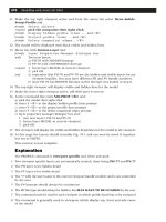
4 Erase the black border and pan the drawing to suit
5 Set and save the four UCS positions as fig(a)
6 Restore UCS BASE and make SECT the current layer
7 Select the HATCH icon from the Draw toolbar and using the Boundary Hatch dialogue box:
a) pick User defined pattern type
b) set angle to 30 and spacing to 8
c) use the Pick Points< option and:
1. select a point within the 1234 plane then right-click/enter
2. Preview-right click-OK
8 Repeat the HATCH icon selection and:
a) using the Pick Points option pick a point within the 6789 plane and:
prompt Boundary Definition Error dialogue box – Fig. 8.2
respond pick OK then <RETURN>
b) using the Select Objects option pick the four lines of the 6789 plane then right-
click/enter and:
1. set angle to –45 and spacing to 5
2. Preview-right click-OK
9 The result of the two hatch operations is displayed in fig(b) with plane 1234 having the
correct hatching, but plane 6789 has none, the hatching having been added to the plane
of UCS BASE.
10 Use the HATCH icon and try and add hatching to the vertical planes 1564 and 3467.
a) Not possible?
b) Unable to hatch the boundary message at the command line
c) Why is this?
11 Erase the ‘wrong’ hatching and restore UCS TOP
12 Hatch the top plane (6789) using the HATCH icon with:
a) pick points option
b) angle –45 and spacing 5
13 Add hatching to the two vertical planes remembering to restore UCS LEFT and UCS
RIGHT – fig(c). Use your own angle and spacing values.
14 Task
a) Erase the added hatching then add the following predefined hatch patterns using the
information given:
UCS Pattern Scale Angle
BASE HEX 1 –10
TOP HONEY 2 0
LEFT SQUARE 2 10
RIGHT STARS 2 0
c) the result is fig(d)
d) this completes example 1 which does not have to be saved.
Hatching in 3D 53
Figure 8.2 The Boundary Definition Error Message box.
modelling with AutoCAD.qxd 17/06/2002 15:38 Page 53
Example 2
1 Open the drawing C:\MODR2002\3DWFM and refer to Fig. 8.3
2 a) erase all text and any dimensions
b) erase the smaller triangle and lower circle on the base plane
c) make layer SECT current
d) restore UCS TOP
3 Select the HATCH icon and:
a) Predefined pattern type: scroll and pick STARS
b) set scale to 1 and angle to 0
c) select Pick Points: pick internal points in the TWO top planes then right-click/enter
d) preview-right click-OK
4 Restore UCS FRONT and with the HATCH icon:
a) pattern type: ZIGZAG
b) scale: 1.5 and angle: 30
c) select objects: pick the four lines of front vertical plane then right-click/enter
d) preview-right click-OK
5 Repeat the HATCH icon selection and add the following hatch patterns:
UCS Pattern Scale Angle Selection type
SLOPE1 TRIANG 1 25 pick points
VERT1 HOUND 2.5 0 pick points
6 Menu bar with View-Hide and the model is as before. Hatching a wire-frame model
does not produce a hide effect.
7 Save your completed hatched model but not as MODR2002/3DWFM.
8 Note
In the two hatch exercises we used the one layer (SECT) for all hatching. It is sometimes
desirable to have a different layer for each current UCS that is to be used for hatching.
This is a user decision.
54 Modelling with AutoCAD 2002
Figure 8.3 Hatch exercise with 3DWFM.
modelling with AutoCAD.qxd 17/06/2002 15:38 Page 54
Summary
1 Hatching is a 2D concept
2 Hatching a 3D model requires the UCS to be set to the ‘plane’ which is to be hatched
3 a) both user-defined and pre-defined hatch patterns can be used
b) both the select objects and pick points methods are permitted
4 Hatching a 3D wire-frame model does not produce a hide effect
Assignments
Two hatch activities have been included, both using previously created wire-frame
models these being MACFARAMUS’s shaped block and rectangular topped pyramid.
The procedure with both activities is to:
1 Open the saved drawing
2 Freeze layer DIM, or erase the dimensions if necessary
3 Add appropriate hatching, making new hatch layers for each UCS position if required –
your decision!
4 Use the pick points method where possible
5 Save the completed model.
Activity 6: The shaped block of MACFARAMUS
1 Restore the appropriate UCS and add the following user defined hatching:
UCS Angle Spacing
FRONT 45 8
RIGHT 45 8
MID 45 8
SLOPE 45 8
2 When complete save the model as MODR2002\SHBLOCK for recall.
Activity 7: The rectangular topped pyramid of MACFARAMUS.
1 Using the correct UCS, add the following predefined hatch patterns:
UCS Pattern Scale Angle
four ‘shaped’ planes BRICK 2 0
four vert ‘top’ planes BRSTONE 1 0
the horiz top surface EARTH 1.5 0
2 Save the complete hatched model as MODR2002\PYRAMID
3 Note:
a) extra lines required for the hatch effect?
b) the viewpoint has been altered for effect.
Hatching in 3D 55
modelling with AutoCAD.qxd 17/06/2002 15:38 Page 55
Tiled viewports
1 Up until now, all the models that have been created have been displayed as a single object
on the screen. The graphics screen can however, be divided into a number of separate
viewing areas called viewports and each viewport can display different viewpoints of
a model.
2 Viewports are interactive, i.e. what is drawn in one viewport is automatically displayed
in the others and the user can switch between viewports when creating a model.
Viewport layouts (configurations) can be saved thus allowing different displays of the
same model to be stored for future recall.
3 Viewports are essential with 3D modelling as they allow different views of the model to
be displayed on the screen simultaneously.
4 When used with the VIEWPOINT command (next chapter) the user has a very powerful
3D draughting tool.
5 There are two types of viewport (displayed in Fig. 9.1) these being:
a) Tiled or fixed
b) Untiled or floating
6 The type of viewport which is displayed is controlled by the TILEMODE system variable
and:
a) Tilemode 1: tiled viewports – the default setting. These viewports are fixed and cannot
be altered by the user
b) Tilemode 0: untiled viewports – can be altered by the user.
7 In this chapter we will only investigate TILED viewports and leave the untiled viewport
discussion to a later chapter when we will investigate model and paper space.
8 Making viewports can be activated by keyboard entry or from the menu bar.
Chapter 9
Figure 9.1 Tiled and untiled viewports.
modelling with AutoCAD.qxd 17/06/2002 15:38 Page 56
Example 1
This exercise is rather long, but persevere with it.
1 Open your 3DWFM drawing of the wire-frame model on the black border with layer
MODEL current and UCS BASE.
2 Deactivate all floating toolbars and display the model without any text, dimensions or
hatching. Erase or freeze layers?
3 At the command line enter TILEMODE <R> and:
prompt Enter new value for TILEMODE<1>
and observe the 1 default then press ESC
4 The TILEMODE value of 1 indicates that only TILED viewports can be used. The same
condition is also evident with:
a) Status bar: word MODEL is displayed
b) Menu bar: View-Viewports indicate that Polygonal Viewport and Object are not
available for selection
5 Menu bar with View-Viewports-3 Viewports and:
prompt Enter a configuration [Horizontal/Vertical/Above
enter R <R> – the right configuration option
6 The drawing screen will:
a) be divided into three separate ‘areas’ – one large at the right and two smaller to the
left. The three viewports will ‘fill the screen’ as Fig. 9.2(a)
b) display the same view of the model in the three viewports
Tiled viewports 57
Figure 9.2 Viewport example 1.
modelling with AutoCAD.qxd 17/06/2002 15:38 Page 57
7 Move the mouse about the screen and:
a) the large viewport will display the cursor cross-hairs and is the ACTIVE viewport,
i.e. it is ‘current’
b) the other viewports will display an arrow and these viewports are NON-ACTIVE
8 Any viewport can be made active by:
a) moving the mouse into the viewport area
b) left-click
c) try this for yourself a few times
9 At the command line enter -VPORTS <R> and:
prompt Enter an option [Save/Restore/Delete/
enter S <R> – the save option
prompt Enter name for new viewport configuration
enter CONF1 <R>
10 Make the upper left viewport active and select the menu bar sequence View-Viewports-
2 Viewports and:
prompt Enter a configuration option [Horizontal/Vertical
enter V <R> – the vertical option
and the top left viewport will be further divided into two equal vertical viewports,
each displaying the model layout
11 Make the lower left viewport active and menu bar with View-Viewports-4 Viewports
to display an additional four viewports of the model
12 At the command line enter -VPORTS <R> and:
prompt Enter an option [Save/Restore/
enter S <R> – the save option
prompt Enter name for new viewport configuration
enter CONF2 <R>
13 With the lower left viewport active, enter -VPORTS <R> at the command line and:
prompt Enter an option [Save/Restore
enter 3 <R> – the 3 viewport option
prompt Enter a configuration option [Horizontal/Vertical/Above
enter H <R> – the horizontal option
14 The lower left viewport will be further divided into another three viewports and at this
stage your screen should resemble Fig. 9.2(b)
15 Make the lower left viewport active and enter -VPORTS <R> then 4 <R> and the
following message will be displayed at the prompt line: The current viewport is too small to divide
16 Save the screen viewport configuration as CONF3 – easy?
17 a) make the large right viewport active
b) menu bar with View-Viewports-1 Viewport
c) original screen displayed?
d) zoom-all needed?
18 Menu bar with View-Viewports-4 Viewports to ‘fill the screen’ with four viewports
of the model
19 Using the menu bar View-3D Views selection make each viewport current and set
different viewpoints using the following:
Viewport 3D View
top left SE Isometric
top right NE Isometric
lower right Plan-Current UCS
lower left Front
58 Modelling with AutoCAD 2002
modelling with AutoCAD.qxd 17/06/2002 15:38 Page 58
20 The screen display should resemble Fig. 9.2(c)
21 Save the screen configuration as CONF4
22 Task
Restore the screen to a single viewport configuration to display the original model layout
23 At the command line enter -VPORTS <R> and:
prompt Enter an option [Save/Restore
enter R <R> – the restore option
prompt Enter name of viewport configuration to restore
enter CONF1 <R>
and screen displays the first saved configuration
24 Restore the other three saved viewport configurations using the command line –VPORTS,
then restore the display to a single viewport
25 Notes
a) The command line entry -VPORTS gives the user the viewport options at the
command line. This was deliberate for this first example.
b) Generally the viewports command is activated from the menu bar in dialogue box form.
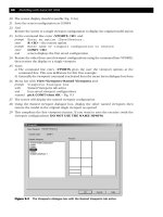
26 Menu bar with View-Viewports-Named Viewports and:
prompt Viewports dialogue box
with Named Viewports tab active
and four saved viewport configurations
respond pick CONF3 then OK – Fig. 9.3
27 The screen will display the named viewport configuration
28 Using the Named viewport dialogue box, display the other named named viewports then
restore the model in the original single viewport as opened
29 This completes the first viewport exercise. If you want to save the exercise (with the
viewport configurations) DO NOT USE THE NAME 3DWFM
Tiled viewports 59
Figure 9.3 The Viewports (Named Viewports tab) dialogue box.
modelling with AutoCAD.qxd 17/06/2002 15:38 Page 59
Example 2
The first exercise used an already created 3D model to investigate the viewport command
and configurations. This current exercise will create a new 3D wire-frame model
interactively using a four viewport configuration with preset 3D viewpoints. This will
allow the user to ‘see’ the model being created in all four viewports at the one time.
1 Open your 3DSTDA3 template file to display the black border at a 3D viewpoint with
layer MODEL current.
2 Menu bar with View-Display-UCS Icon and check both On and Origin are active (tick)
– they should be!
3 Menu bar with Tools-New UCS-Origin and:
prompt Specify new origin point
enter 50,50,0 <R>
and icon moves to the entered point and is displayed as a UCS icon
4 Save this UCS position as BASE
5 Menu bar with View-Viewports-New Viewports and:
prompt Viewports dialogue box with New Viewports tab active
respond 1. New name: enter SCREEN DISPLAY 1
2. Standard viewports: pick Four: Equal
3. Apply to: Display
4. Setup: scroll and pick 3D
5. Change view to: do not alter (Fig. 9.4)
6. pick OK
60 Modelling with AutoCAD 2002
Figure 9.4 Viewports (New Viewports tab) dialogue box.
modelling with AutoCAD.qxd 17/06/2002 15:38 Page 60
6 The screen will display a four viewport configuration with the black border displayed in
each. Note the ‘appearance’ of the icon in the top two, and lower right viewports – it
has the same configuration in each, despite the different viewpoints set in the New
Viewports dialogue box (respond 4 above)
7 Making each viewport active in turn enter the following:
a) at the command line enter UCSVP <R> and:
prompt Enter new value for UCSVP<1>
enter 0 <R>
b) at the command line enter ZOOM <R> then 0.9 <R>
8 The screen layout at this stage is similar to Fig. 9.5(a)
9 Note: we will discuss UCSVP in a later chapter
10 With the lower left viewport active, construct the model base using the LINE icon with:
Start point 0,0,0 <R> pt1
Next point @200,0,0 <R> pt2
Next point @0,120,0 <R> pt3
Next point @200<180,0 <R> pt4
Next point close – fig(b) in 3D
11 Using the LINE command construct the front vertical side with:
Start point Intersection icon of pt1
Next point @20,0,100 <R> pt5
Next point @120,0,0 <R> pt6
Next point Intersection icon of pt2
Next point right-click/enter – fig(c) in 3D
Tiled viewports 61
Figure 9.5 Construction of model for viewport example 2.
modelling with AutoCAD.qxd 17/06/2002 15:38 Page 61
12 The top surface is created with the LINE command and:
Start point Intersection icon of pt6
Next point @0,80,0 <R> pt7
Next point @–120,0,0 <R> pt8
Next point Intersection icon of pt5
Next point right-click/enter – fig(d) in 3D
13 Add the sloped sides with lines joining points 3–7 and 4–8 as fig(e) in 3D
14 Make layer OBJECTS (blue) current and draw a circle with centre at 80,40,100 and with
a radius of 25 – fig(f) in 3D
15 Menu bar with Draw-Surfaces-3D Surfaces-Box3d and:
prompt Specify corner of box and enter: 80,30,0
prompt Specify length of box and enter: 50
prompt Specify width of box and enter: 40
prompt Specify height of box and enter: 30
prompt Specify rotation angle of box about Z axis and enter: 20
16 a) Make layer TEXT current
b) Rotate UCS about X axis by 90 and save as FRONT
c) Menu bar with Draw-Text-Single Line Text and add the text item AutoCAD,
centred on 80,50 with height 20 and rotation 0
17 a) Set a 3 point UCS on the right sloped surface with:
1. origin: midpoint of line 23 – Fig. 9.5(e)
2. x axis: intersection of pt 3
3. y axis: perpendicular to line 67
4. save UCS as SLOPE
b) Add the single line text item R2002, centred on –5,50 with a height of 15 and a
rotation angle of 0
18 The complete four viewport configuration display should be similar to Fig. 9.6
19 Save the drawing as MODR2002\TEST3D
20 This completes the two exercises on viewports
21 Notes
1. A new system variable was used during this exercise, this being UCSVP. This variable
determines whether the UCS in an active viewport will ‘reflect’ the UCS orientation
of that active viewport and:
a) UCSVP 0: unlocked, i.e. the UCS will reflect the UCS of the current active viewport
b) UCSVP 1: locked, i.e. UCS is independent of the UCS in the current active viewport
2. The default UCSVP value is 1, i.e. locked
3. It is recommended that the UCSVP is set to 0, i.e. it always reflects the UCS
position in any active viewport
4. The UCSVP must be set in every created viewport
62 Modelling with AutoCAD 2002
modelling with AutoCAD.qxd 17/06/2002 15:38 Page 62
Summary
1 Viewports allow multi-screen configurations to be set
2 There are two types of viewport – TILED and UNTILED
3 The viewport type is controlled by the system variable TILEMODE and:
a) TILEMODE 1: tiled viewports (fixed)
b) TILEMODE 0: untiled viewports (movable) – more later
4 Tiled viewports can have between 1 and 4 ‘divisions’ and ‘fill the screen drawing area’
5 Multi-screen viewports are generally used with the viewpoint command and their full
benefit will not be appreciated until the various viewpoint options are discussed
6 Multiple viewport layouts are essential to 3D modelling.
Tiled viewports 63
Figure 9.6 Completed viewport example 2 – TEST3D.
modelling with AutoCAD.qxd 17/06/2002 15:38 Page 63
3D views (Viewpoint)
3D Views (or viewpoints) determine how the user ‘looks’ at a model and has been used
in previous chapters without any discussion about how it is used. In this chapter we will
investigate the command in detail using previously created models. When combined with
viewports, the user has a very powerful draughting aid – multiple viewports displaying
different views of a model.
The viewpoint command has the following selection options:
a) Isometric views: SW, SE, NE, NW
b) Orthographic views: Top, Bottom, Left, Right, Front, Back
c) Plan view: to current UCS, WCS, named UCS
d) Viewpoint: with rotate, compass and tripod, vector options
e) Viewpoint Presets: dialogue box selection
f) Real-time 3D rotation
g) New Viewports dialogue box
In this chapter we will investigate all of the above selections.
The Viewpoint ROTATE option
This option requires two angles to be entered by the user:
a) the angle in XY plane from the X-axis – the view direction
b) the angle from XY plane – the inclination (tilt)
1 Open your MODR2002\3DWFM drawing and:
a) erase any dimensions and hatching.
b) leave all text items – they will act as a ‘reference’ as the model is viewed from different
angles.
2 Layer MODEL current, UCS BASE and SE Isometric viewpoint
3 Refer to Fig. 10.1 section A
4 At the command line enter VPOINT <R> and:
prompt ***Switching to WCS***
and Current view direction
then Specify a view point or [Rotate]<display compass and
tripod>
enter R <R> – the rotate option
prompt Enter angle in XY plane from X-axis
enter 40 <R>
prompt Enter angle from XY plane
enter 0 <R>
prompt ***Returning to UCS***
then Regenerating drawing
and model displayed as fig(a1), i.e. looking towards the right-rear side from a
horizontal ‘stand-point’ – the view direction.
Chapter 10
modelling with AutoCAD.qxd 17/06/2002 15:38 Page 64
5 At the command line enter VPOINT <R> and:
prompt Specify a view point or [Rotate]
enter R <R> – the rotate option
prompt Enter angle in XY plane from X-axis and enter: 90 <R>
prompt Enter angle from XY plane and enter: 0 <R>
and model displayed as fig(a2)
6 Repeat the VPOINT-Rotate command from the command line and enter the following
angle values at the prompts:
prompt 1 prompt 2 fig
215 0 a3
330 0 a4
7 Restore the original SE Isometric viewpoint and refer to Fig. 10.1 section B
8 Use the VPOINT-Rotate command and enter the following angles at the prompts:
prompt 1 prompt 2 fig
045b1
0 135 b2
0 270 (–90) b3
0 –45 (315) b4
9 Restore the SE Isometric viewpoint and refer to Fig. 10.1 section C. Activate the VPOINT-
Rotate command and enter the following angles:
prompt 1 prompt 2 fig
40 70 c1
40 –30 c2
–20 20 c3
10 Restore the original SE Isometric viewpoint
11 Task
Restore some other UCS settings, e.g. SLOPE1, VERT1, etc. and repeat the viewpoint
rotate command using some of the above angle entries. The model display should be
unaffected by the UCS position Think about the prompt ***Switching to the WCS***
12 Explanation of option
a) Prompt 1: angle in XY plane from the X-axis
This is the viewer’s standpoint on the XY horizontal plane looking towards the
model, i.e. it is your view direction. If this angle is 0degs you are looking at the model
from the right side. If the angle is 270degs you are looking onto the front of the model.
The value of this angle can be between 0degs and 360degs. It can also be positive or
negative and remember that 270degs is the same as –90degs
b) Prompt 2: angle from the XY plane
This is the viewer’s ‘head inclination’ looking at the model, i.e. it is the angle of tilt.
A 0degs value means that you are looking at the model horizontally and a 90degs value
is looking vertically down. The angle of tilt can vary between 0degs and 360degs and
be positive or negative and: positive tilt: looking down on the model negative tilt:
looking up at the model
13 Note
The reader must realise that the displays in Fig. 10.1 have been ‘scaled’ to fit the one
sheet, and that your model displays will be larger than those illustrated.
3D views (Viewpoint) 65
modelling with AutoCAD.qxd 17/06/2002 15:38 Page 65
VPOINT ROTATE using the presets dialogue box
1 3DWFM displayed at SE Isometric setting with UCS BASE?
2 Menu bar with View-3D Views-Viewpoint Presets and:
prompt Viewpoint Presets dialogue box – Fig. 10.2
with 1. viewing angle: absolute to WCS
2. angle from X-axis: 315 – left-hand ‘clock’
3. angle from XY plane: 35.3 – right-hand ‘arc’
3 This dialogue box allows:
a) viewing angle to be absolute to WCS or relative to UCS
b) angles to be set by selecting circle/arc position
c) angles to be set by altering values at From: line
d) plan views to be set
4 Respond to the dialogue box with:
a) do not change to absolute to WCS
b) change the X-axis angle from 315 to 150
c) change the XY plane angle from 35.3 to 10
d) pick OK
e) the model will be displayed at the entered viewpoint angles
5 Make UCS SLOPE1 current
66 Modelling with AutoCAD 2002
Figure 10.1 3D Views – the VPOINT ROTATE option with 3DWFM.
modelling with AutoCAD.qxd 17/06/2002 15:38 Page 66
6 Menu bar with View-3D Views-Viewpoint Presets and:
a) make Relative to UCS active – black dot
b) leave the two angle values as 150 and 10
c) pick OK
d) the model is displayed at the entered viewpoint angles but differs from the step 4
display due to the UCS setting
7 Task
a) Try some other entries from the Viewpoint Presets dialogue box using both selection
methods, i.e. the clock/arc and altering the angles.
b) Investigate the difference in the display with the Absolute to WCS and Relative to
UCS selections
c) Restore Absolute to WCS
d) Restore UCS BASE and the SE Isometric viewpoint
8 This completes the viewpoint rotate exercise. Do not save any changes to the 3DWFM model.
3D views (Viewpoint) 67
Figure 10.2 The Viewpoint Presets dialogue box.
modelling with AutoCAD.qxd 17/06/2002 15:38 Page 67
The Viewpoint COMPASS and TRIPOD option
This option allows the user to set ‘infinite viewpoints’ and has been called the bulls-eye
and target method – for obvious reasons. We will demonstrate the command with a
different model so:
1 Open the MODR2002\TEST3D model created during the viewport exercise and refer to
Fig. 10.3
2 Ensure UCS BASE is current and make the lower left viewport active, i.e. the 3D viewport
3 Menu bar with View-Viewports-1 Viewport to display a single viewport of the model at
a 3D viewpoint. This model ‘fills the screen’.
4 Menu bar with View-3D Views-Viewpoint and:
prompt 1. model ‘disappears’
2. screen displays the XYZ tripod and the compass, which was previously
termed the bulls-eye target
3. cursor replaced by a small cross (+)
4. axes and cross(+) move as mouse is moved
respond move the cross (+) into the circle quadrant indicated in Fig. 10.3(a) and left-
click
and model displayed at this viewpoint, and is viewed from above
68 Modelling with AutoCAD 2002
Figure 10.3 3D Views – the Viewpoint compass and tripod option with TEST3D.
modelling with AutoCAD.qxd 17/06/2002 15:38 Page 68
5 At the command line enter VPOINT <R> and:
prompt ***Switching to WCS***
then Specify a viewpoint or [Rotate]<display compass and tripod>
respond press <RETURN>
prompt tripod and compass displayed
respond move the cross (+) into the circle quadrant indicated in Fig. 10.3(b)
then left-click
and model displayed at this new viewpoint
6 Repeat the tripod viewpoint option (menu bar or command line) and position the cross
(+) in the quadrants indicated in Fig. 10.3
i.e. (c)–(d): within the inner circle
(e)–(h): between the inner and outer circles
7 Task
When you are capable of using the compass and tripod, try the following:
a) position the + at different points on the two axes and observe the resultant displays
b) position the + at different points on the circle circumferences and note the displays
8 Explanation of option
a) The ‘bulls-eye’ is in reality a representation of a glassglobe and the model is located
at the centre of the globe. The XY plane is positioned at the equator. The north
pole of the globe is at the circle centres and the two concentric circles represent the
surface of the world, stretched out onto a flat plane with:
circle centre : the north pole
inner circle : the equator
outer circle : the south pole
b) As the cross(+) is moved about the circles, the user is moving around the surfaces
of the globe and:
Cross (+) position View result
in inner circle above equator, looking down on model
in outer circle below equator, looking up at model
on inner circle looking horizontally at model
below horizontal viewing from the front
above horizontal viewing from the rear
9 This completes the tripod option exercise. Do not save changes.
3D views (Viewpoint) 69
modelling with AutoCAD.qxd 17/06/2002 15:38 Page 69
The Viewpoint VECTOR option
1 Open MODR2002\3DWFM with UCS BASE and SE Isometric viewpoint.
2 Erase any dimensions and hatching, but leave the text items as they will act as a
‘reference’ as the model viewpoint is altered.
3 Refer to Fig. 10.4
4 Menu bar with View-3D Views-Viewpoint and:
prompt ***Switching to WCS***
then Current view direction
and Specify a view point or [Rotate]
enter 0,0,1 <R>
prompt ***Returning to the UCS***
and 1. the model will be displayed at the entered viewpoint
2. it is a top view – fig(a)
3. it ‘fills the screen’
6 At the command line enter VPOINT <R> and:
prompt Specify a view point or [Rotate]
enter 0,–1,0 <R>
and model displayed as fig(b) – a front view
70 Modelling with AutoCAD 2002
Figure 10.4 3D Views – the Viewpoint VECTOR option with 3DWFM.
modelling with AutoCAD.qxd 17/06/2002 15:38 Page 70
7 Repeat the viewpoint vector option (menu bar or command line) and enter the following
coordinates at the prompt line:
co-ords view fig
1,0,0 from right c
0,1,0 from rear d
–1,0,0 from left e
0,0,–1 from below f
1,1,1 3D from above g
–1,–1,–1 3D from below h
8 Restore the original SE Isometric viewpoint
9 Task
Try some vector entries for yourself then restore the original SE Isometric viewpoint
10 Explanation of option
a) The vector option allows the user to enter x,y,z coordinates. These are the coordinates
of the viewers ‘stand point’ looking at the model which is considered to be at the
origin. Thus if you enter 0,0,1 you are ‘standing’ at the point 0,0,1 looking towards
the origin. As this point is on the positive Z axis you are looking down on the model,
i.e. a top view.
b) The actual numerical value of the vector entered does not matter, i.e. 0,0,1; 0,0,12;
0,0,99.99; 0,0,3456 are all the same viewpoint entries. I prefer to use the number 1,
hence 0,0,1; –1,0,0 etc
c) Certain vector entries give the same display as rotate options and the following lists
some of these similarities:
vector rotate view
0,0,1 0,90 top
0,–1,0 270,0 front
1,0,0 0,0 right
0,1,0 90,0 rear
–1,0,0 180,0 left
0,0,–1 0,–90 bottom
1,1,1 45,35 3D from above
–1,–1,–1 –135,–35 3D from below
11 This completes the vector option. Do not save any changes.
3D views (Viewpoint) 71
modelling with AutoCAD.qxd 17/06/2002 15:38 Page 71
The Isometric viewpoints
The isometric 3D views allow the user to view a model from four ‘preset’ viewpoints,
these being SW, SE, NE and NW. These four viewpoints are used extensively as they
allow easy access to viewing a model in 3D.
1 Open model TEST3D to display the four viewport configuration saved from the previous
chapter.
2 Restore UCS BASE with layer MODEL current
3 Making the appropriate viewport active, menu bar with Views-3Dviews and set the
following viewpoints:
viewport viewpoint
top left SW Isometric
top right SE Isometric
lower right NE Isometric
lower left NW Isometric
4 When the viewpoints have been entered, zoom-all in each viewport and the result should
be Fig. 10.5. This does not need to be saved
5 Notes:
a) The four preset isometric viewpoints only allow viewing from above. If a model is to
be viewed from below, another option is required. My choice for this is VPOINT-Rotate
with a negative second angle value.
b) The equivalent VPOINT-Rotate angles for the four isometric presets are:
3D View angle in XY plane angle from XY plane
SW Isometric 225 35.3
SE Isometric 315 35.3
NE Isometric 45 35.3
NW Isometric 135 35.3
72 Modelling with AutoCAD 2002
Figure 10.5 3D Views – the ISOMETRIC Presnts with the TEST3D model.
modelling with AutoCAD.qxd 17/06/2002 15:38 Page 72
The Orthographic viewpoints
There are six ‘preset’ orthographic viewpoints these being Top, Bottom, Left, Right, Front
and Back. The options are independent of the UCS position.
1 Open model 3DWFM and erase any dimensions and hatching
2 Restore UCS BASE with layer MODEL current. Refer to Fig. 10.6
3 Menu bar with View-Viewports-2 Viewports and:
prompt Enter a configuration option and enter: H <R>
4 With the top viewport active, menu bar with View-Viewports-3 Viewports and:
prompt Enter a configuration option and enter: V <R>
5 With the bottom viewport active, repeat step 4
6 Making each viewport active, menu bar with View-3D Views and set the following
orthographic viewpoints:
viewport viewpoint
top left top
top middle bottom
top right left
lower right right
lower middle front
lower right back
7 This layout does not need to be saved.
3D views (Viewpoint) 73
Figure 10.6 3D Views – the six orthographic presets with the 3DWFM model.
modelling with AutoCAD.qxd 17/06/2002 15:38 Page 73
Viewpoint PLAN
This viewpoint selection was discussed during the chapter on the UCS and gives a view
perpendicular to a UCS position.
1 Open the four viewport configuration TEST3D and:
a) create a single viewport configuration of the 3D view
b) set any 3 viewport configuration
c) UCS FRONT current and refer to Fig. 10.7
2 Make any viewport active and menu bar with View-3D Views-Plan View-Current
UCS and the model will be displayed as fig(a).
3 It is a plan view perpendicular to the UCS FRONT XY plane.
4 With another viewport active, menu bar with View-3D Views-Plan View-World UCS
and the model will be displayed as fig(b)
5 Make the third viewport active and select the menu bar sequence View-3D Views-Plan
View-Named UCS and:
prompt Enter name of UCS and enter: SLOPE <R>
6 The model will be displayed as a view perpendicular to the XY plane of UCS SLOPE.
7 This layout does not need to be saved.
74 Modelling with AutoCAD 2002
Figure 10.7 3D Views – the PLAN options with model TEST3D.
modelling with AutoCAD.qxd 17/06/2002 15:38 Page 74
The VIEW command
Different views of a model can be saved within the current drawing, thus allowing the
operator to create a series of ‘pictures’. These could be of the model being constructed,
of a completed model at differing viewpoints etc. These views (pictures) can be recalled
at any time.
1 Open the 3DWFM model and erase any dimensions and hatching (or freeze the
appropriate layers)
2 Model displayed at SE Isometric viewpoint with UCS BASE and layer MODEL current
3 At the command line enter –VIEW <R> and:
prompt Enter an option [?/Orthographic/Delete/Restore/Save
enter S <R> – the save option
prompt Enter view name to save
enter V1 <R>
4 Menu bar with View-3D Views and set to NW Isometric
5 Menu bar with View-Named Views and:
prompt View dialogue box – Named Views tab active
respond pick New
prompt New View dialogue box
respond 1. enter View name: V2
2. ensure Current display active, i.e. black dot
3. Save UCS with view active (tick)
4. UCS name: BASE – Fig. 10.8
5. pick OK
prompt View dialogue box with V2 added to list
respond pick OK
6 Menu bar with View-3D Views and set to SW Isometric
7 Menu bar with View-Named Views and from the View dialogue box:
a) pick New
b) View name: V3 with current display, UCS BASE then OK
c) View dialogue box as Fig. 10.9
d) pick OK
8 At the command line enter -VIEW <R> and:
prompt Enter an option
enter R <R> – the restore option
prompt Enter view name to restore
enter V1 <R>
and saved view V1 displayed
9 Menu bar with View-Named Views and:
prompt View dialogue box
respond 1. pick V3
2. pick Set Current
3. pick OK
and screen displays the saved V3 view
10 Task
a) create, save and display some other views
b) investigate the Details option from the Named Views tab
c) investigate the Orthographic & Isometric Views tab
d) investigate altering the UCS with saved views
11 When complete, restore the SE Isometric viewpoint. Save if required but not as 3DWFM.
12 Note
Do not confuse the VIEW command with the View option of the UCS command. They
are two entirely different concepts.
3D views (Viewpoint) 75
modelling with AutoCAD.qxd 17/06/2002 15:38 Page 75
76 Modelling with AutoCAD 2002
Figure 10.10 The Viewports dialogue box (New Viewports tab).
Figure 10.8 The New View dialogue box.
Figure 10.9 The View dialogue box (Named Views tab).
modelling with AutoCAD.qxd 17/06/2002 15:38 Page 76
Viewports dialogue box
Viewpoints can be set using the various options of the 3D View command as well as from
the Viewports dialogue box. To investigate the Viewports dialogue box further:
1 Open the 3DWFM model – no dimensions or hatching
2 UCS BASE and layer MODEL both current
3 Menu bar with View-Viewports-Named Viewports and:
prompt Viewport dialogue box
respond 1. pick the New Viewports tab
2. enter View name: LAY1
3. pick Standard viewports: Four: Right
4. Setup: 3D
5. note Preview
6. leave view names as given – Fig. 10.10
7. pick OK
4 The screen will display a four viewport configuration with the appropriate views of the
model as Fig. 10.11. This is easier than creating a viewport layout then setting the
viewpoint?
3D views (Viewpoint) 77
Figure 10.11 3DWFM using the Viewports dialogue box (New Viewports tab).
modelling with AutoCAD.qxd 17/06/2002 15:38 Page 77