Modelling with AutoCAD 2002 Episode 6 pps
Bạn đang xem bản rút gọn của tài liệu. Xem và tải ngay bản đầy đủ của tài liệu tại đây (1007.21 KB, 30 trang )
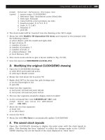
2 Refer to Fig. 22.3 which again only displays the 3D viewport
3 Menu bar with Modify-3D Operation-Mirror 3D and:
prompt Select objects
respond window the model then right-click
prompt Specify first point on mirror plane (3 points) or [Object/
Last/
enter XY <R> – the XY plane option
prompt Specify point on XY plane<0,0,0> and: right click
prompt Delete source objects<Yes/No> and enter: Y <R>
then PAN to suit – fig(b)
4 The model at this stage has the AMBIGUITY effect of all 3D models, i.e. are you looking
down or looking up? Hence HIDE!
5 At the command line enter MIRROR3D <R> and:
prompt Select objects
respond window the model then right-click
prompt Specify first point on mirror plane
respond Intersection icon and pick pt1
prompt Specify second point on mirror plane
respond Intersection icon and pick pt2
prompt Specify third point on mirror plane
respond Intersection icon and pick pt3
prompt Delete source object<Yes/No> and enter: Y <R>
then PAN to suit, then HIDE – fig(c)
3D geometry commands 143
Figure 22.3 The MIRROR 3D command using 3DGEOM model.
modelling with AutoCAD.qxd 17/06/2002 15:39 Page 143
6 Activate the Mirror 3D command and:
a) window the model the right-click
b) select the YZ plane option
c) pick intersection of point A as a point on the plane
d) enter Y to delete source objects prompt
e) pan and hide – fig(d)
7 Using the Mirror 3D command:
a) window the model the right-click
b) select the ZX option
c) enter –50,–50 as a point on the ZX plane
d) accept the N default delete source objects option
e) pan and hide – fig(e)
8 Shade and 3D orbit, then investigate the layout tabs
9 Save if required. We will not refer to this drawing again.
3D Array
The 3D array command is similar in operation to the 2D array. Both rectangular and polar
arrays are possible, the rectangular array having rows and columns as well as levels in
the Z direction. The result of a 3D polar array requires some thought!
Rectangular
1 Open the 3DGEOM drawing, UCS BASE, Model tab active and refer to Fig. 22.4 which
displays the MVLAY1 tab
2 At the command line enter 3DARRAY <R> and:
prompt Select objects
respond window the model then right-click
prompt Enter the type of array [Rectangular/Polar]
enter R <R> – rectangular option
prompt Enter the number of rows( )<1> and enter: 2 <R>
prompt Enter the number of columns(|||)<1> and enter: 3 <R>
prompt Enter the number of levels(…)<1> and enter: 4 <R>
prompt Specify the distance between rows( ) and enter: 120 <R>
prompt Specify the distance between columns(|||) and enter: 120 <R>
prompt Specify the distance between levels(…) and enter: 100 <R>
3 The model will be displayed in a 2×3×4 rectangular matrix pattern but will ‘be off the screen’.
4 Zoom-extents then hide to display the complete array
5 With MVLAY1 tab active, zoom centre about the point 170,110,185 (why these
coordinates) at 400 magnification (550 in 3D view)
6 Hide the model – Fig. 22.4 then Gouraud shade the 3D viewport.
7 Try the 3D orbit command with the shaded model.
8 This exercise does not need to be saved.
144 Modelling with AutoCAD 2002
modelling with AutoCAD.qxd 17/06/2002 15:39 Page 144
Polar
1 Open 3DGEOM, UCS BASE in Model tab
2 Menu bar with Modify-3D Operation-3D Array and:
prompt Select objects
respond window the model then right-click
prompt Enter the type of array and enter: P <R>
prompt Enter the number of items and enter: 5 <R>
prompt Specify the angle to fill and enter: 360 <R>
prompt Rotate arrayed objects and enter: Y <R>
prompt Specify center point of array
enter 150,150,0 <R>
prompt Specify second point on axis if rotation
enter @0,0,100 <R> i.e. a vertical line
3 Zoom-all then investigate the MVLAY1 tab – Fig. 22.5(a)
4 Undo the 3D polar array
5 Activate the 3D array command and:
a) window the original model then right-click
b) enter a polar array type
c) number of items: 5
d) angle to fill: 360
e) rotate as copied: Y
f) centre point of array and enter: –50,0,0 <R>
g) second point on axis and enter: @0,100,0 <R>
6 Zoom-all then hide and shade
7 Investigate the MVLAY1 tab which will need a zoom-extents and then a zoom scale factor
– Fig. 22.5(b)
3D geometry commands 145
Figure 22.4 The 3D ARRAY (rectangular) command using 3DGEOM model.
modelling with AutoCAD.qxd 17/06/2002 15:39 Page 145
8 Note:
a) The first polar array was about a vertical line, the second about a horizontal line. Think
about the entered coordinates
b) The ARRAY icon/dialogue box is for 2D arrays only
9 This exercise is complete and need not be saved.
Align
The align commands can be used in 2D or 3D and allows objects (models) to be aligned
with each other.
1 Open your MV3DSTD template file, MVLAY1 tab with UCS BASE and layer MODEL
current. Refer to Fig. 22.6
2 Using the Surfaces toolbar create the following objects:
Box Wedge
corner 0,0,0 160,0,0
length 100 100
wedge 80 80
height 50 50
rotation 0 0
colour red blue
3 Copy the box and wedge:
a) base point: 0,0,0
b) second point: @150,150
4 Set the running object snap to Intersection
146 Modelling with AutoCAD 2002
Figure 22.5 The 3D ARRAY (polar) using the 3DGEOM model.
modelling with AutoCAD.qxd 17/06/2002 15:40 Page 146
5 Menu bar with Modify-3D Operation-Align and:
prompt Select objects
respond pick a blue wedge then right-click
prompt Specify first source point and pick point 1s
prompt Specify first destination point and pick point 1d
prompt Specify second source point and pick point 2s
prompt Specify second destination point and pick point 2d
prompt Specify third source point and pick point 3s
prompt Specify third destination point and pick point 3d
6 The blue wedge will be aligned with its sloped surface on the top of the box as (a)
7 At the command line enter ALIGN <R> and:
a) pick the copied red box then right-click
b) pick first source/destination points: pick a and x
c) pick second source/destination points: pick b and y
d) pick third source/destination points: pick c and z
e) the red box will be aligned onto the sloped surface of the wedge as (b)
8 This completes the align exercise.
3D geometry commands 147
Figure 22.6 The ALIGN command with 3D objects.
modelling with AutoCAD.qxd 17/06/2002 15:40 Page 147
3D extend and trim
Objects can be trimmed and extended in 3D irrespective of the objects’ alignment. The
two commands are very dependent on the UCS position.
1 Open your MV3DSTD template file and refer to Fig. 22.7
2 Using the LINE icon draw a square with:
start point: 0,0 next point: @100,0 next point: @0,100
next point: @–100,0 next point: close
3 Multiple copy the square with:
a) base point: 0,0
b) second point: @0,0,120 and: @0,0,180
4 Scale the top square about the point 50,50,180 by 0.5
5 Draw in the four vertical lines between the two large squares, then draw the following
four lines:
line start point next point colour
1 25,25,180 @0,–5,–30 blue
2 75,25,180 @5,0,–30 green
3 75,75,180 @0,5,–30 cyan
4 25,75,180 @0,0,–60 magenta
6 Change the viewpoint in the 3D viewport with VPOINT-ROTATE and angles of 300 and
30. The model will be displayed as fig(a).
Figure 22.7 The EXTEND and TRIM commands.
148 Modelling with AutoCAD 2002
modelling with AutoCAD.qxd 17/06/2002 15:40 Page 148
Extend
1 With the 3D viewport active, restore UCS RIGHT and select the EXTEND icon from the
Modify toolbar and:
prompt Select objects
respond pick line ab then right-click
prompt Select object to extend or [Project/Edge/Undo]
enter E <R> – the edge option
prompt Enter an implied edge extension mode [Extend/No extend]
enter E <R> – the extend option
prompt Select object to extend or [Project/Edge/Undo]
enter P <R> – the project option
prompt Enter a projection mode [None/Ucs/View]
enter U <R> – the current UCS option
prompt Select object to extend
respond pick blue line 1 then right-click/enter
2 Repeat the EXTEND command using the entries E,E,P,U as step 1 and:
a) extend the green line 2 to edge bc with UCS RIGHT
b) extend the cyan line 3 to edge cd with UCS FRONT
3 The extended lines are displayed as fig(b)
Trim
1 Still with the 3D viewport active, restore UCS BASE and select the TRIM icon from the
modify toolbar and:
prompt Select objects
respond pick line wx then right-click
prompt Select object to trim or [Project/Edge/Undo]
enter P <R> – the project option
prompt Enter a projection option [None/Ucs/View]
enter V <R> – the view option
prompt Select object to trim
respond a) make the top right viewport active
b) pick the blue line then right-click/enter
2 Repeat the TRIM command with P and V entries as step 1 and:
a) trim the green line to edge xy, picking the green line in the top left viewport at the
select object to trim prompt
b) trim the cyan line to edge yz, picking the cyan line in the top right viewport at the
select object to trim prompt
3 The coloured lines have now been extended and trimmed ‘to the top surface’ of the large
red box – fig(c)
Task
1 Draw four lines connecting the ‘bottom ends’ of the blue, green, cyan and magenta lines
2 Hatch this area
3 Find the hatched area and perimeter. My values were:
Area: 3350 and Perimeter: 232.65
3D geometry commands 149
modelling with AutoCAD.qxd 17/06/2002 15:40 Page 149
Summary
1 The commands Rotate3D, Mirror3D and 3DArray are specific to 3D models.
2 Rotate 3D allows models to be rotated about the X,Y and Z axes as well as two specified
points and about objects
3 Mirror 3D allows models to be mirrored about the XY, YZ and ZX axes as well as three
specified points and objects
3 A rectangular 3D Array is similar to the 2D command but has ‘levels’ in the Z direction.
The result of the polar 3D array can be difficult to ‘visualise’
4 3D models can be aligned with each other.
5 The trim and extend commands can be used in 3D, the result being dependent on the
UCS position. Generally objects are trimmed or extended ‘to a plane’.
150 Modelling with AutoCAD 2002
modelling with AutoCAD.qxd 17/06/2002 15:40 Page 150
Blocks and Wblocks
in 3D
3D blocks and wblocks are created and inserted into a drawing in a similar manner
as 2D blocks and wblocks. The UCS position and orientation is critical. In this chapter
we will:
a) create a chess set using blocks
b) create a wall-clock as wblocks
c) save both the models for rendering exercises
Creating the models for the blocks
1 Open your MV3DSTD template file with MVLAY1 tab, layer MODEL and UCS BASE
current, and the lower left viewport active.
2 In each viewport, zoom centre about the point 120,90,50 at 275 magnification. Refer to
Fig. 23.1
Chapter 23
Figure 23.1 The four 3D block details.
modelling with AutoCAD.qxd 17/06/2002 15:40 Page 151
3 With the lower left viewport active, create the following two 3D box objects:
box1 box2
corner 0,0,0 0,120,0
length 80 80
width 80 80
height 10 10
rotation 0 0
colour number 126 number 220
4 Restore UCS FRONT and make the upper right viewport active.
5 Draw a line with start point: 150,–10 and next point: @0,80
6 In paper space, zoom-window the top right viewport, then return to model space
7 a) Draw the pawn outline as a polyline from: 150,0 using your own design but with the
‘overall’ sizes given as reference.
b) Set SURFTAB1 to 16
c) With the REVOLVED SURFACE icon from the Surfaces toolbar, revolve the pawn
outline about the vertical line – full circle
d) The pawn colour is to be red
8 Still with UCS FRONT, draw a line with start point: 210,–10,–60 and next point: @0,120
9 a) Draw the rook outline as a polyline from: 210,0,–60 using the reference sizes given
or create your own design
b) Revolve the rook polyline about the vertical line (360 degs)
c) The rook colour is to be red
10 Erase the two vertical lines
11 Restore UCS BASE and models displayed as Fig. 23.1.
Making the blocks
1 With the lower left viewport active and UCS BASE, menu bar with Draw-Block-Make and:
prompt Block Definition dialogue box
respond 1. enter name: SQ1
2. enter base point as X: 0; Y:0; Z: 0
3. pick Select objects and pick the green coloured box then right-click
4. Objects: ensure Delete active
5. Preview: Create icon from block geometry active
6. enter description: FIRST SQUARE
7. ensure insert units: millimeters (dialogue box as Fig. 23.2)
8. pick OK
2 The green coloured square will be ‘made into a block’ and should disappear from the
screen due to respond 4
3 Using the Block Definition dialogue box, make the other three blocks using the same
method as step 1 with the following information:
first second third
name SQ2 PAWN ROOK
insertion pt 0,120,0 150,0,0 210,60,0
object purple box 3D pawn 3D rook
description SECOND SQUARE PAWN PIECE ROOK PIECE
4 Now erase the original polyline outlines which should be displayed
5 Activate the block definition dialogue box and scroll at name and the four created blocks
should be listed (PAWN, ROOK, SQ1, SQ2) in alphabetical order.
152 Modelling with AutoCAD 2002
modelling with AutoCAD.qxd 17/06/2002 15:40 Page 152
6 Note:
a) The command line BLOCK <R> entry will display the Block Definition dialogue box
b) The command line entry –BLOCK <R> will allow block creation from the command line
c) At the command line enter –BLOCK <R> and:
prompt Enter block name or [?] and enter: ? <R> – query option
prompt Enter block(s) to list and enter: * <R>
prompt Text window with information about the four defined blocks
respond cancel the text window
Inserting the blocks
1 Four ‘blank’ viewports should be displayed with MVLAY1 tab, UCS BASE, layer MODEL
and the 3D viewport active
2 Menu bar with Insert-Block and:
prompt Insert dialogue box
respond 1. scroll at name and pick SQ1
2. deactivate all on-screen prompts, i.e. no tick
3. enter insertion point as X: 0; Y: 0; Z: 0
4. enter scale as X: 1; Y: 1; Z: 1
5. enter rotation as 0
6. dialogue box as Fig. 23.3
7. pick OK
and the green 3D box block will be displayed at the 0,0,0 insertion point
3 Repeat the Insert-Block sequence with:
a) scroll and pick SQ2
b) ensure on-screen prompts are off
c) insertion point of X: 80; Y: 0; Z: 0
d) scale of X: 1; Y: 1; Z: 1 and rotation: 0
e) pick OK and the purple 3D box block displayed adjacent to the green 3D box
Block and Wblocks in 3D 153
Figure 23.2 Block Definition dialogue box for SQ1.
modelling with AutoCAD.qxd 17/06/2002 15:40 Page 153
4 Zoom centre about 320,320,100 at 700 in all viewports
5 With the 3D viewport active, complete the 64 square chess board using one of the
following methods:
a) inserting each block SQ1 and SQ2
b) multiple copy the two inserted boxes
c) rectangular array
d) note: I used multiple copy
6 At the command line enter –INSERT <R> and:
prompt Enter block name and enter: PAWN <R>
prompt Specify insertion point and enter: 40,120,10 <R>
prompt Enter X scale factor and enter: 1 <R>
prompt Enter Y scale factor and enter: 1 <R>
prompt Specify rotation angle and enter: 0 <R>
and the red pawn piece will be displayed on top of the left second row square
7 Now insert the ROOK full-size with 0 rotation at the insertion point of 40,40,10 using
either the Insert dialogue box or the –INSERT command line entry.
8 a) Rectangular array the red pawn for 1 row and 8 columns, the column distance being
80. Row distance is 0?
b) Copy the eight pawns from: 40,80,10 to: @0,400,0
c) Multiple copy the rook from a base point of 40,40,10 to second points of: @560,0,0;
@0,560,0; @560,560,0
9 Task
a) Alter the layout to display a three viewport configuration, remembering to make layer
VP current
b) set the viewpoints to display a 3D, top and front view
c) Change the colour of one set of prawns and rooks to blue. This may not be as simple
as you think. The inserted blocks must be exploded before the colour can be changed.
Decide whether to use the PICKFIRST variable set to:
i) 0: CHANGE at command line then pick the objects
ii) 1: pick the objects then the Properties icon
d) re-centre the model in each viewport about 320,320,100 at 1100 magnification in the
3D viewport and 700 in the other two
10 When complete, the layout should resemble Fig. 23.4 and should be saved as
MODR2002\CHESS for the activity part of the chapter.
154 Modelling with AutoCAD 2002
Figure 23.3 The Insert dialogue box for SQ1.
modelling with AutoCAD.qxd 17/06/2002 15:40 Page 154
Creating the models for the Wblocks
1 Open the MV3DSTD template file with MVLAY1 tab, UCS BASE and zoom centre about
125,0,100 at 300 magnification in all viewports. Refer to Fig. 23.5
2 The wblocks will be created using the WCS, so menu bar with Tools-New UCS-World
3 With the top right viewport active, layer MODEL current rotate the WCS about the X
axis with menu bar sequence Tools-New UCS-X and enter 90 as the rotation angle
4 Create the three outlines for parts of a wall clock with:
a) draw the body as lines using the 0,0,0 start point and the reference sizes given. Use
the Modify-Object-Polyline command to ‘convert’ the five lines into a single polyline
object
b) draw the face as an octagon circumscribed in a circle with centre at 90,90,0 and a
radius of 40
c) draw the dial as a 30 radius circle, centre at 90,10,0
5 Draw the following three lines:
a) line 1, start point: 150,0 next point: @0,0,40
b) line 2, start point: 200,0 next point: @0,0,15
c) line 3, start point: 250,0 next point: @0,0,8
6 The three wall clock components will be created as tabulated surface models, so set
SURFTAB1 to 16
Block and Wblocks in 3D 155
Figure 23.4 The chess layout after the block insertions.
modelling with AutoCAD.qxd 17/06/2002 15:40 Page 155
7 With the TABULATED SURFACE icon from the Surfaces toolbar:
prompt Select object for path curve
respond pick the BODY polyline
prompt Select object for direction vector
respond pick line 1 at end indicated by the donut
and extruded red tabulated surface model of wall clock body
8 Repeat the tabulated surface command and:
a) select the FACE octagon as the path curve and line 2 as the direction vector at end
indicated
b) select the DIAL circle as the path curve and line 3 as the direction vector at end
indicated
9 Change the colour of the tabulated surface models:
FACE: blue
DIAL: green
10 The layout at this stage should resemble Fig. 23.5
156 Modelling with AutoCAD 2002
Figure 23.5 Information for creating the three wblocks.
modelling with AutoCAD.qxd 17/06/2002 15:40 Page 156
Making the Wblocks
1 Menu bar with Tools-New UCS-World to restore the WCS and make the lower left
viewport active
2 At the command line enter WBLOCK <R> and:
prompt Write Block dialogue box
respond 1. Source: Objects
2. Base point: X: 0; Y: 0; Z: 0
3. Objects: Delete from drawing
4. pick Select objects and:
prompt Select objects at command line
respond pick the red body then right-click
prompt Write Block dialogue box
respond 1. Destination file name: BODY
2. Location: C:\modr2000 (or your named folder)
3. Insert units: Millimeters – Fig. 23.6
4. pick OK
3 Create another two wblocks using the same procedure as step 2 with the following
information:
wblock2 wblock3
Insertion base point 90,0,90 90,0,10
Objects blue object green object
File name FACE DIAL
Location C:\modr2002 C:\modr2002
Block and Wblocks in 3D 157
Figure 23.6 The Write Block dialogue box for BODY.
modelling with AutoCAD.qxd 17/06/2002 15:40 Page 157
Inserting the three wblocks
1 Menu bar with File-Close and pick No to save changes
2 Menu bar with File-New and ‘open’ your MV3DSTD template file with UCS BASE, layer
MODEL, MVLAY1 tab and lower left viewport active
3 Restore the WCS
4 Menu bar with Insert-Block and:
prompt Insert dialogue box
respond pick Browse
prompt Select Drawing File dialogue box
respond 1. scroll and pick the C: drive
2. scroll and pick C:\modr2000 (or your named folder)
3. pick BODY and note the preview
4. pick Open
prompt Insert dialogue box
respond 1. cancel the on-screen prompts
2. enter insertion point as X: 0; Y: 0; Z: 0
3. all scale factors 1 and rotation angle 0
4. pick OK
and the red body will be displayed at the 0,0,0 insertion point
5 Activate the Insert dialogue, select the Browse option and insert the other wblocks with
the following information:
File name: FACE DIAL
Insertion point: 0,–40,130 0,–55,130
X and Y scale: 1 1
Rotation angle: 0 0
6 Zoom centre about the point 0,–30,80 at 200 magnification in all viewports – Fig. 23.7
7 Investigate the other layout tabs, centring the model using the following suggestion:
Zoom-Extents then Zoom to scale 1.5
8 Hide and shade from the model tab and try 3D orbit
9 Save the model as MODR2002\WALL
158 Modelling with AutoCAD 2002
Figure 23.7 The completed wall clock created from inserted wblocks.
modelling with AutoCAD.qxd 17/06/2002 15:40 Page 158
Summary
1 3D blocks and wblocks are created and inserted in a similar manner to 2D blocks and
wblocks
2 With 3D blocks, the position of the UCS is important
3 With 3D wblocks it is strongly recommended that the WCS be restore when creating
and inserting the wblocks
4 It is also recommended that wblocks are ‘stored’ in the same folder as drawing file from
they were created and into which they will be inserted
5 Wblocks which are inserted ‘unexploded’ into a drawing become blocks within that
drawing. It is therefore recommended that wblocks are exploded as they are inserted.
The AutoCAD Design Centre
Before leaving this chapter and attempting the activities, we will investigate using the
Design Centre. All AutoCAD users should now be aware that blocks created in a drawing
can be inserted into any other drawing using the Design Centre.
1 Close all existing drawings then open the 3DSTDA3 standard sheet created before
model/paper space was discussed
2 Menu bar with Tools-AutoCAD Design Center to display the Design Center dialogue
box and position to suit
3 From the Design Centre menu bar select Preview and Description
4 In the hierarchy side (left) of the dialogue box:
a) navigate the your named folder
b) scroll until CHESS.dwg is displayed
c) expand CHESS – pick the (+) at drawing icon
d) explore Blocks, i.e. right-click on Blocks
e) dialogue box displayed as Fig. 23.8
Block and Wblocks in 3D 159
Figure 23.8 The Design Centre dialogue box with blocks explored for C:\MODR2002\CHESS.
modelling with AutoCAD.qxd 17/06/2002 15:40 Page 159
5 Right-click the SQ1 icon from the Design Center palette and:
prompt Shortcut menu
respond pick Insert block
prompt Insert dialogue box
with SQ1 named and dialogue box as before
respond cancel the dialogue box and the Design Center
6 This exercise was to demonstrate that the Design Center can be used to insert ANY block
from any drawing into any other drawing
Assignments
Two activities have been included for you to attempt, one involving the partially
completed chess set, and the other using two previously saved drawings, one of which
will be inserted as a wblock into the other.
ACTIVITY 15: CHESS SET
1 Recall the drawing CHESS saved earlier in this chapter to display the 64 square chess
board with the two sets of red and blue pawns and rooks.
2 Design the other chess pieces – KNIGHT, BISHOP, KING and QUEEN using the same
method as the worked example:
a) draw the outline as a polyline
b) use the revolved surface command to create the piece as a 3D surface model
c) the actual shape of the pieces is at your discretion.
d) the information given in the Activity 15 drawing is for reference purposes only
e) ensure that your start point for the outline is known – it will be useful as the block
insertion point
3 Create a block of each created piece
4 Insert the created blocks onto the chess board
5 Complete the chess set layout, remembering to change the colours of the pieces to red
and blue as appropriate.
6 Save as MODR2002\CHESS.
7 Investigate the various shade options with the completed model
8 Note: the model layout displayed in activity 15 was produced by Craig Matthewman. Craig
was a full-time student on the HNC CADD course at Motherwell College and his design
was interesting. He gave his permission for the layout to be included as an activity.
ACTIVITY 16: Palace of Queen NEFERSAYDY built by MACFARAMUS.
MACFARAMUS was last encountered building the palace for queen NEFERSAYDY.
Unfortunately this palace was to be built on a flat topped hill and you have to create the
layout using an existing drawing and inserting another drawing into it as a wblock.
1 Open the drawing MODR2002\HILL of the edge surface model created as activity 13
2 Insert the wblock drawing file MODR2002\PALACE of the 3D objects created as activity 14
3 The palace has to be positioned at the centre point of the hill top, and the coordinates
of this point as 0,0,100. This is the only help given.
4 Optimise all the layout tabs for maximum effect.
5 When complete save the layout as MODR2002\HILLPAL
160 Modelling with AutoCAD 2002
modelling with AutoCAD.qxd 17/06/2002 15:40 Page 160
Dynamic viewing
Dynamic viewing is a powerful (yet underused) command which is very useful with 3D
modelling as it allows models to be viewed from a perspective viewpoint. The command
also allows objects to be ‘cut-away’ enabling the user to ‘see inside’ models. Dynamic
viewing has its own terminology which is obvious when you are familiar with the
command, but can be confusing to new users.
The basic concept of dynamic viewing is that the user has a CAMERA which is
positioned at a certain DISTANCE from the model – called the TARGET. The user is
looking through the camera lens at the model and can ZOOM in/out as required. The
viewing direction is from the camera lens to a TARGET POINT on the model. The
camera can be moved relative to the stationary target, and both the camera and target
can be turned relative to each other. The target can also be TWISTED relative to the
camera. Two other concepts which the user will encounter with the dynamic view
command are the slider bar and the perspective icon. The slider bar allows the user
to ‘scale’ the variable which is current, while the perspective icon is displayed when the
perspective view is ‘on’.
Figure 24.1(A) displays the various dynamic view concepts of:
a) the basic terminology
b) the slider bar
c) the perspective icon
Chapter 24
Figure 24.1 Dynamic view terminology and AutoCAD’s DVIEWBLOCK ‘house’.
modelling with AutoCAD.qxd 17/06/2002 15:40 Page 161
The dynamic view command has eleven options, these being:
CAmera,TArget,Distance,POints,Pan,Zoom,TWist,CLip,Hide,Off,Undo
The option required is activated by entering the CAPITAL letters at the command line,
e.g. CA for the camera option, TW for twist etc.
We will investigate the dynamic view command with two examples:
1 using AutoCAD’s dynamic view ‘house’
2 with a previously created and saved model
Note
1 Dynamic view is a model space concept, and cannot be used in paper space.
2 Dynamic view is viewport independent, i.e. if the command is used in a specific
viewport, the model display in the other viewports will not be affected.
3 The command is activated by entering DVIEW <R> at the command line
Example 1 – AutoCAD’s ‘house’
AutoCAD has a ‘drawing’ – actually a type of block – which can be used as an interactive
aid with the dynamic view command. We will use this house block to demonstrate some
of the options so:
1 Close any existing drawings and start a new metric drawing from scratch and refer to
Fig. 24.1(B)
2 At the command line enter DVIEW <R> and:
prompt Select objects or <use DVIEWBLOCK>
respond <RETURN> i.e. accept the DVIEWBLOCK default
a) prompt Enter option
[Camera/Target/Distance/Points/Pan/Zoom/Twist/Clip/
Hide/Off/Undo]
and some coloured lines appear on the screen
enter Z <R> – the zoom option
prompt slider bar with scale displayed at top of screen
and Specify zoom scale factor
enter 0.5 <R>
and full plan view of house – fig(a)
b) prompt Enter option [CAmera/TArget/etc
enter CA <R> – the camera option
prompt ghost image of house which moves as mouse moved
and Specify camera location or enter angle from XY plane
enter 30 <R>
prompt Specify camera location or enter angle in XY plane from
X axis
enter 30 <R>
and 3D view of house – fig(b)
c) prompt Enter option [CAmera/TArget/etc
enter H <R> – the hide option
and house displayed with hidden line removal – fig(c)
162 Modelling with AutoCAD 2002
modelling with AutoCAD.qxd 17/06/2002 15:40 Page 162
d) prompt Enter option [CAmera/TArget/etc
enter CL <R> – the clip option
prompt Enter clipping option [Back/Front/Off]
enter F <R> – the front clip option
prompt Specify distance from target or [set to Eye(camera)/ON/OFF]
enter 40 <R>
prompt Enter option [CAmera/TArget/etc
enter H <R> – the hide option
and house displayed ‘cut-away’ similar to fig(d)
e) enter U <R> – undoes the hide effect of (d)
enter U <R> – undoes the clip effect of (d)
enter U <R> – undoes the hide effect of (c)
and leave house with Camera option displayed
and command prompt line options
then read the explanation before proceeding
Explanation of the dynamic view command
Dynamic view is an interactive command and the various options can be used one after
the other. The undo (U) option will undo the last option performed, and can be used
repeatedly until all the options entered have been ‘undone’. Some of the options have
been used to demonstrate how the command is used, these options being zoom, camera,
clip, hide and undo. The hide option is very useful as it allows the model to be displayed
when other options have been entered, and removes the ‘ambiguity’ effect from the
model. The command can be used with all 3D models, i.e. extruded, wire-frame, surface
and solid. The command is also viewport independent, i.e. it can be used in any
viewport without affecting the display in other viewports. The AutoCAD ‘house’ is a user-
reference, and if a model is displayed on the screen, this model will assume the house
orientation when the dynamic view command is completed. This will be investigated
during the next example.
Dynamic viewing 163
Figure 24.2 The various DVIEW options with DVIEWBLOCK – AutoCAD’s house.
modelling with AutoCAD.qxd 17/06/2002 15:40 Page 163
The house displayed on the screen has been left with the Camera option with entered
angles of 30 and 30. We will continue with the screen display and investigate the other
dynamic view options. This means that you have to enter the various options and values
as prompted.
Refer to Fig. 24.2 which displays one entry (with hide) from the exercises which follow.
CAmera
1 This option is used to direct the camera at the target and the camera can be ‘tilted’
relative to the target. These are two angle prompts:
prompt 1 angle in the XY plane, between –90degs and +90degs
prompt 2 angle from the XY plane, between –180degs and +180degs
2 The angles can be:
a) toggled using the ghost image as a guide
b) entered directly from the keyboard
3 Using the CAmera option enter the following angle values:
angle in XY plane angle from XY plane
a)35 35
b) 35 –35
c) –35 35
d) –35 –35
4 The option can be considered similar to VPOINT-ROTATE
5 When all the above entries have been completed, return the camera angles to the original
30 and 30, but do not exit the command.
TArget
1 This option allows the target (the model) to be tilted relative to the camera. The two
angle prompts are the same as the camera option:
prompt 1 angle in the XY plane
prompt 2 angle from the XY plane
2 The angles can be toggled or entered from the keyboard
3 Using the TArget option enter the following angle values:
angle in XY plane angle from XY plane
a)35 35
b) 35 –35
c) –35 35
d) –35 –35
4 The option can be used to give the same effect as the camera option, but it should be
remembered that the camera and target are being ‘tilted’ in the ‘opposite sense’ to each other
5 When all angles have been entered, restore the camera to angles of 30 and 30, but do
not exit the command.
TWist
1 A very useful option as it allows the ‘plane’ on which the target is ‘resting’ to be twisted
through an entered angle. This angle can be positive or negative and have values between
0 and 360degs
2 The prompt with this option is: Specify new view twist angle
3 The result of the option is dependent on the CAmera/Target angles
164 Modelling with AutoCAD 2002
modelling with AutoCAD.qxd 17/06/2002 15:40 Page 164
4 Using the TWist option enter angle values of:
a) 35 b) –35 c) 180 d) –90
5 This is one of the few AutoCAD commands which allows models to be ‘flipped’ over by
180degs.
6 When the four twist angles have been viewed with the hide effect, restore the original
twist angle of 0, with the camera options of 30 and 30. Do not exit the command.
CLip
1 The clip option of the dynamic view command is probably of the most useful of all the
options, as it allows models to be ‘cut-away’, thus allowing the user to ‘see inside’ the model.
2 The user selects a (F)ront or (B)ack clip and then decides on the clip distance either:
a) using the slider bar
b) entering a value at the command line
3 The result of the clip option is dependent on the CAmera/TArget angles as well as the
‘size’ of the model on the screen
4 With the CAmera angles set to 30 and 30, activate the front clip option and move the
slider bar until the ghost image displays a clip effect then right-click
5 When the clip option attempts are complete, undo the various effects with U <R> until
the house is again displayed with the CAmera settings of 30 and 30.
POints
1 This option allows the model (the target) to be viewed from a specific ‘stand point’, the
user looking at a specific point on the target.
2 Two sets of coordinates need to be specified:
a) the target point coordinates to be looked at
b) the coordinates of the camera – the user
3 The coordinate entries can be absolute or relative
4 When this option is used, the PAn option is also usually needed
5 The result does not depend on the CAmera or TArget options
6 Use the Point option with the following entries:
target point camera point
a) 0,0,0 1,0,0
b) 0,0,0 0,1,0
c) 0,0,0 0,0,1
d) 0,0,0 1,1,0
e) 0,0,0 1,0,1
f) 0,0,0 1,1,1
g) 1,2,3 0,0,0
h) 0,0,0 1,2,3
7 The option is similar to the VPOINT-VECTOR command.
8 When all the points entries have been entered, restore the camera angles of 30 and 30,
but do not exit the command.
Dynamic viewing 165
modelling with AutoCAD.qxd 17/06/2002 15:40 Page 165
Distance
1 Alters the distance between the camera and the target
2 The distance can be:
a) entered as a value from the command line
b) toggled using the slider bar
3 With the distance option, enter some values e.g.:
a) 1000 b) 1500 c) 2500 d) 5000
4 The distance option introduces true perspective to the model
5 When the distance option has been used, and the command is exited, the zoom
command cannot be used.
6 Restore the original CAmera option of 30 and 30
Zoom
1 This option does what you would expect – it ‘zooms the model’
2 The zoom factor can be:
a) entered as a value from the keyboard
b) toggled using the slider bar
3 Try some zoom entries e.g.:
a)1 b) 0.75 c) 0.5 d) 0.25
4 Restore the original CAmera effect (30,30) and use the zoom option with a 0.5 scale factor
three times.
Pan
1 This option is similar to the AutoCAD PAN command, but the ‘real-time’ pan effect is
not available.
2 The user selects (or enters) the pan displacement
Hide
1 Will display the model with a hide effect
2 Removes any ambiguity
Undo
1 Entering U <R> will undo the last option of the DVIEW command
2 Can be used repetitively until all the option entries have been undone
eXit
1 Entering X <R> will end the dynamic view command and a blank screen will be
returned
2 The blank screen is because we did not have any model displayed, the AutoCAD ‘house’
being a visual aid indicating what any model would ‘look like’
3 With ‘real models’, the model orientation will be similar to the ‘house’ orientation when
the DVIEW command has been exited, as will now be investigated.
4 If the DVIEW command is still active, enter X <R>
5 This first exercise is now complete.
166 Modelling with AutoCAD 2002
modelling with AutoCAD.qxd 17/06/2002 15:40 Page 166
Example 2 – an 3D model
In this example we will use the dynamic view command with a previously created model.
1 Open the ruled surface model MODR2002\ARCHES created during chapter 16 with UCS
BASE, layer MODEL. Re-centre the model about the point 50,10,75 at 150 mag.
2 Make the upper left viewport active and refer to Fig. 24.3
3 At the command line enter DVIEW <R> and:
prompt Select objects or use <DVIEWBLOCK>
respond <RETURN>
prompt AutoCAD’s house as an ‘end view’ in the active viewport
and dynamic view options
enter CA <R>
prompt Angle from XY plane and enter: –20 <R>
prompt Angle in XY plane and enter: 30 <R>
prompt dynamic view options and enter: X <R>
4 The model will be displayed with house CAmera configuration as fig(b) with hide
5 With the top right viewport active, enter DVIEW <R> at the command line and:
prompt Select objects or use <DVIEWBLOCK>
respond window the model then right-click
prompt dynamic view options
enter TW <R>
prompt Specify view twist angle and enter: –90 <R>
prompt dynamic view options and enter: X <R>
and Model displayed with new twist as fig(c)
Dynamic viewing 167
Figure 24.3 Dynamic view example 2 using MODR2002\ARCHES.
modelling with AutoCAD.qxd 18/06/2002 11:23 Page 167