Modelling with AutoCAD 2002 Episode 11 pdf
Bạn đang xem bản rút gọn của tài liệu. Xem và tải ngay bản đầy đủ của tài liệu tại đây (1.83 MB, 30 trang )
2 Activate the setup View command and:
a) UCS option with UCS BASE
b) view scale: 0.25
c) view centre: 200,200
d) position viewport: pick to suit yourself
e) name: MYVIEW1
f) options: X
3 Repeat the setup View command:
prompt Enter an option [Ucs/Ortho/Auxiliary/Section]
enter O <R> – the ortho option
prompt Specify side of viewport to project
respond pick lower horizontal line of viewport
prompt Specify view center
enter 200,100 <R>
prompt Specify view centre
and pick to suit yourself
prompt Specify corners of viewport
respond pick to suit your layout
prompt Enter view name and enter: MYVIEW2 <R>
prompt Enter an option and continue with next part of exercise
4 Setup view command still active with options:
a) select the Ortho option
b) pick right vertical line of second viewport
c) view center: pick a point to right to suit
d) viewport corners: pick points to suit
e) view name: MYVIEW3
f) options
g) select the Auxiliary option
h) Inclined plane points: pick to suit – see Fig. 43.3
i) Side to view from: pick ‘below’ the inclined line
j) view center: pick a point to suit
k) viewport corners: position to suit
l) view name: MYVIEW4
m) options
n) select the section option
o) cutting plane points: pick points as indicated in Fig. 43.3
p) side to view from: pick to right of the section line
q) view scale: 0.25
r) view center: pick to suit
s) viewport corners: pick to suit the layout
t) name: MYVIEW5
u) options: X to end command
5 Linetype HIDDEN and three HP variables set?
6 Activate the Setup Drawing command and pick the five viewports to display the layout
with hidden line removal and section detail as Fig. 43.3
7 Freeze layer VPORTS if required
8 Question
In our three setup examples the type of layout has not been mentioned, i.e. first or third
angle. I am sure that you are aware of the projections obtained, the first two examples
being in first angle, and the third example being in third angle. This is the ‘power’ of
the setup commands. First and third angle detail layouts can be obtained for models by
simply picking the relevant view centre points
9 Save the exercise as it is now complete.
The setup commands 293
modelling with AutoCAD.qxd 17/06/2002 15:43 Page 293
Summary
1 The set View and Drawing commands allow the user to layout multi-view drawings
without the need to create viewports and set viewpoints
2 Both commands can be activated:
a) by selecting the icon from the Solids toolbar
b) from the menu bar with Draw-Solids-Setup
c) from the command line with SOLVIEW and SOLDRAW
3 The setup View command has options which allow views to be created:
a) relative to a named UCS
b) as an orthographic view relative to a selected viewport
c) as an auxiliary view relative to an inclined plane
d) as a section view relative to a cutting plane
4 When used, the View command creates viewport specific layers, these being relative to
the viewport handle number with the following names:
-VIS for visible lines
-HID for hidden lines
-DIM for dimensions
-HAT for hatching but only if the section option is used
5 The View command requires the user to:
a) enter the view scale
b) position the viewport centre point
c) position the actual viewport corners
6 With the Ortho option, both First and Third angle projections can be obtained dependent
on which side the new viewport is to be placed
7 The section option requires that the system variables HPNAME, HPANG and HPSCALE
are set. It is usual to use the ANSI31 hatch pattern name, but this is not essential.
AutoCAD defaults the ANGLE hatch pattern
8 The Drawing command will display models which have been created with the View
command:
a) with visible and hidden detail
b) as a section if the section option has been used
9 It is recommended that the linetype HIDDEN be loaded before the Drawing command
is used.
10 The hidden linetype appearance is controlled by the LTSCALE system variable.
11 The user now has two different methods for creating multi-view layouts of solid models:
a) using the A3SOL template file idea which sets the viewports and viewpoints prior to
creating the model. Profiles can then be extracted to display hidden detail
b) using the VIEW and DRAWING commands with a solid composite to layout the
drawing in First or Third angle projection with sections and auxiliary views as
required.
c) it is now the user’s preference as to which method is used
12 Dimensions can now be added to models:
a) using viewport specific layers
b) using paper space dimensioning
c) using the setup commands
294 Modelling with AutoCAD 2002
modelling with AutoCAD.qxd 17/06/2002 15:43 Page 294
The final composite
We have now covered virtually every concept of solid modelling within the AutoCAD
draughting package. The next chapter will introduce the user to rendering, but before
that we will make a final solid model using the various techniques that have been
discussed. The model is quite involved, so try not to miss out any of the steps, especially
those which set a new UCS position.
The three examples selected to demonstrate the View and Drawing commands have used
previously created models. This example will create a new model ‘from scratch’.
1 Open your A3SOL template/drawing file with layer MODEL, UCS BASE and make the
model tab active. We will use this tab to create the model and then set up our drawing
layout with the MVLAY1 tab
2 Set ISOLINES to 6 and refer to Fig. 44.1
3 The new model will be created from five primitives, each requiring a new UCS position.
Chapter 44
Figure 44.1 Construction of the computer link model.
modelling with AutoCAD.qxd 17/06/2002 15:43 Page 295
Primitive 1: the base
1 Rotate the UCS about the X axis by 90 and save as PRIM1
2 Draw a polyline:
a) start point: 0,50
b) next point: @60,0
c) next point: @0,–40
d) arc option with endpoint: @–10,–10
e) line option to: @–40,0
f) arc option with endpoint: @–10,10
g) line option to: close
3 Zoom extents then zoom to a scale of 3
4 Solid extrude the polyline for a height of 3 with 0 taper
5 Create two cylinders:
a) centre: 30,25,0; radius: 6; height: 3
b) centre: 30,40,0; radius: 3; height: 3
6 Polar array the smaller cylinder about the point 30,25 for 3 items with full circle rotation
7 Subtract the four cylinders from the extruded polyline – fig(a)
Primitive 2: wedge on top of first primitive
1 UCS PRIM1 current
2 Set a new 3 point UCS position with:
a) origin: 0,50,0
b) x-axis: 60,50,0
c) y-axis: 0,50,3
d) save as: PRIM2
3 Create a wedge with:
a) corner: 0,0,0
b) length: 60; width: –3; height: –30
4 Rotate 3D this wedge:
a) about the X axis
b) with 0,0,0 as a point on the axis
c) for 90 degrees
5 Union the wedge and the extruded polyline – fig(b)
Primitive 3: box on top of wedge
1 UCS PRIM2 current
2 Set a new 3 point UCS position with:
a) origin: 60,0,0
b) x-axis: 0,30,0
c) y-axis: 60,0,–3
d) save as: PRIM3
3 Create a solid box with
a) corner: 0,0,0
b) length: 67.08; width: 30; height: –3. Why 67.08?
296 Modelling with AutoCAD 2002
modelling with AutoCAD.qxd 17/06/2002 15:43 Page 296
4 Create a cylinder with:
a) centre: 10,10,0 and:
b) radius: 3; height: –3
5 Rectangular array the cylinder:
a) for 2 rows and 3 columns
b) row offset: 10; column offset: 15
6 a) subtract the six cylinders from the box
b) union the box and the composite – fig(c)
Primitive 4: curved extension on top of box
1 Pan the model to lower part of screen
2 UCS PRIM3 current
3 Set a new 3 point UCS position with:
a) origin: 0,30,–3
b) x-axis: 67.08,30,–3
c) y-axis: 0,30,0
d) save as: PRIM4
4 Zoom in on the ‘free edge’ of the box
5 Draw two line segments with:
start point: 0,0 next point: @0,–15; next point: @50,0
6 Draw a polyline about the ‘top rim’ of the box using the ENDpoint snap and the close
option
7 With the solid revolve command:
a) objects: enter L <R><R> – to select the polyline
b) options: enter O <R> – object option
c) object: pick the left end of long construction line
d) angle: enter 120
8 Erase the two line segments
9 Zoom previous to restore original view
10 Union the revolved component and the composite – fig(d)
Primitive 5: final curved component
1 UCS PRIM4 current
2 Set a new 3 point UCS position with:
a) origin: 67.08,–22.5,–12.99
b) x-axis: 0,–22.5,–12.99
c) y-axis: 67.08,–24,–15.59
d) save as: PRIM5
e) can you work out the three sets of coordinates?
3 Zoom-in on the ‘free end’ of the curved component
4 Draw a polyline about the free end of the curved component using the ENDpoint snap
and the close option
The final composite 297
modelling with AutoCAD.qxd 17/06/2002 15:43 Page 297
5 With the Solid revolve command:
a) objects: enter L <R><R> – to select the polyline
b) options: enter Y <R> – the Y axis
c) angle: enter –30
6 Create a cylinder with:
a) centre: 45,0,15
b) radius: 5
c) centre of other end: @0,10,0
7 Subtract the cylinder from the revolved component, then union the revolved
component with the cylinder – fig(e)
8 Zoom previous to restore the original view
9 The model is now complete, so:
a) Gouraud shade and 3D orbit – impressive?
b) restore 2D wireframe representation at the original viewpoint
10 a) restore UCS BASE
b) save as MODR2002\COMPLINK
Laying out the viewports
This part of the exercise will use the MVLAY1 tab with all options of setup View
command.
1 Pick the MVLAY1 tab name
2 In paper space:
a) erase three viewports but leave the 3D viewport
b) stretch (crossing option) the two vertical edges of the 3D viewport by @50,0 (left side)
and @–50,0 (right side)
c) move the 3D viewport as far left as possible
d) in model space, UCS BASE, layer Model current and zoom the model to suit
3 a) load linetype HIDDEN
b) set the following variables:
HPNAME: ANSI31; HPANG: 0; HPSCALE: 0.5
c) set the LTSCALE value to suit which may change after the layout has been created
4 Activate the setup View command with:
a) UCS option with BASE
b) view scale: 1
c) view center: 175,75
d) viewport corners: pick to suit
e) view name: TOP
f) options: X
5 Using the SOLVIEW command:
a) UCS option with PRIM1 as the named UCS
b) view scale: 1
c) view center: 175,200
d) viewport corners: pick to suit
e) view name: FRONT
f) exit command or continue with command
298 Modelling with AutoCAD 2002
modelling with AutoCAD.qxd 17/06/2002 15:43 Page 298
6 SOLVIEW command with:
a) Ortho option
b) side: pick right vertical side of the second viewport
c) view center: 50,200
d) viewport corners: pick to suit
e) view name: RIGHT
f) exit command or continue with command
7 With the setup View command:
a) activate the Section option
b) pick any point in the second viewport
c) cutting plane points: 30,0 and 30,120
d) side to view from: pick a point to left of section line
e) view scale: 1
f) view center: 0,–110
g) viewport corners: pick to suit
h) view name: SECTION
i) exit or continue with command
8 The final SOLVIEW command is with:
a) the Auxiliary option
b) first point of inclined plane and with the first viewport active, pick ENDpoint of pt1
(see Fig. 44.2)
c) second point of inclined plane: PERP to line 23
d) side to view from: pick to left of inclined line
e) view center: 0,200
f) viewport corners: pick to suit
g) view name: AUXILIARY
h) end the command
The final composite 299
Figure 44.2 Computer link detail drawing using the setup commands.
modelling with AutoCAD.qxd 17/06/2002 15:43 Page 299
9 Using the setup Drawing command, pick the five viewports to display hidden detail and
a section view – linetype HIDDEN loaded?
10 Now optimise the LTSCALE system variable
11 Tasks
a) Interrogate the model in the 3D viewport:
Area: 20196.01
Mass: 26758.64
b) Using the viewport specific -DIM layers, add the dimensions displayed in Fig. 44.2.
The UCS in the new created viewports should be ‘set’ to allow this as the UCSVP
system variable always defaults to 1 when a new viewport is created. Note that a paper
space zoom of the viewport being dimensioned will assist with the dimensions.
c) Freeze the VP and VPORTS layers
d) In paper space, optimise your drawing with suitable text
e) Save the completed exercise – worth the effort?
Assignment
To give some additional practice with the View and Drawing commands I have included
another new model to be created.
Activity 25 – dispenser of MACFARAMUS
One of the discoveries in the city of CADOPOLIS was a container which was thought to
be a dispenser belonging to MACFARAMUS. It is this container which has to be created
as a solid model and then displayed with the setup commands.
1 Use your template file with the Model tab active and when the model is complete use
the MVLAY1 tab as the chapter example
2 Make two new layers BODY blue and TOP green
3 With UCS FRONT, draw the two shapes using the reference sizes in Fig. 44.3. Use the
start points given. Draw as lines/arcs then use the join option of the modify polyline
command to convert the segments into single polylines.
300 Modelling with AutoCAD 2002
Figure 44.3 Reference details for activity 25.
modelling with AutoCAD.qxd 17/06/2002 15:43 Page 300
4 Solid revolve the two polylines for a full circle
5 Create the holes in the top
6 Create a handle from a hexagon, the actual shape being at your discretion – I extruded
a hexagon along a polyline path
7 Use the VIEW and DRAWING commands to create a multi-view layout to display:
a) top and front views with hidden detail
b) two section views through the planes indicated
c) an auxiliary view through an inclined plane at 45 degrees
d) a 3D view
e) I used a view scale of 0.6
8 This activity should highlight a problem when the setup commands are used with a
model containing more than one part. The dispenser has a top and a body, but when
the section option is used, the same hatching is added to both parts. How would different
hatching be added to the two parts?
The final composite 301
modelling with AutoCAD.qxd 17/06/2002 15:43 Page 301
Rendering
Rendering is a topic with its own terminology and we will discuss this terminology by
rendering previously created models. The reader should realise that this chapter is only
a brief introduction to rendering. As we have created several interesting models, it seems
reasonable that we investigate the next step in the modelling process, i.e. the production
of rendered images.
What is render?
Rendering is a process which creates an image (usually in colour) of a 3D surface or solid
model. This image is created from a scene using a view with lights.
How is render activated?
AutoCAD render is automatically loaded into memory when the RENDER command (or
any render option) is selected. The RENDER command can be activated with:
a) the menu bar selection View-Render-Render
b) the RENDER icon from the Render toolbar
c) entering RENDER <R> at the command line
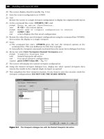
The three methods give the Render dialogue box as Fig. 45.1, which (at present) has
three main areas:
1. the rendering types
2. the scene which is to be rendered
3. the rendering destinations
Chapter 45
Figure 45.1 The Render dialogue box.
1
3
2
modelling with AutoCAD.qxd 17/06/2002 15:43 Page 302
Rendering types
AutoCAD has three ‘types’ of rendering, these being:
1. Render: the basic AutoCAD render option which allows models to be rendered without
the need for scenes, lights or materials. This is the default ‘setting’
2. Photo Real: is a photo-realistic renderer which can display bitmapped and transparent
materials. Volumetric and mapped shadows can also be generated.
3. Photo Raytrace: is a photo-realistic raytrace renderer which can generate reflections,
refraction and precise shadows.
Rendering destination
The rendered image of the model can be:
1. displayed in the current viewport of a multi-screen layout
2. displayed in the render window
3. saved to a file for future recall
Scene to render
Allows the user to select a named scene of the model to render. The user can ‘make’ several
scenes using different views of the model with various lights and materials added.
AutoCAD provides a ‘default’ scene for rendering purposes. This default scene uses a distant
light which cannot be modified by the user. At all times it should be remembered that:
*** A scene is a view with lights added ***
The AutoCAD lights
Adding lights to a model layout immediately improves the render appearance and lights can
be used to illuminate a complete model or to highlight specific parts of the layout. AutoCAD
2002 has four ‘types’ of light available, these being ambient, distant, point and spot.
Ambient light
1 Provides a constant illumination to all surfaces of a model.
2 It is always ‘there’ and does not originate from any particular source.
3 The user has control of the intensity of the ambient light
4 Generally the ambient light intensity should be a low value or the model will be displayed
‘too bright’
5 The default ambient intensity value is 0.3
6 Ambient light on its own does not produce good rendered images.
Distant light
1 Gives a parallel beam in a particular direction
2 The user specifies the target point and the light source location
3 Think of a torch shining at an object
4 Distant light rays extend to infinity on either side of the light source
5 The distant light intensity is not affected by the distance of the source from the target
6 It is recommended that distant lights are positioned at the extents of the drawing
7 Distant lights are used to give a ‘uniform lighting’ facility
8 A single distant light simulates the sun
Rendering 303
modelling with AutoCAD.qxd 17/06/2002 15:43 Page 303
Point light
1 A point light emits light in all directions from its position
2 The user specifies the point light location
3 Think of a light bulb
4 The intensity of a point light is affected by the distance from the model
5 Point lights are used for general lighting effects
6 Point lights are used with spot lights for lighting effects
Spot light
1 Gives a directional cone of light
2 The user specifies the direction of the light and the size of the cone
3 The intensity of a spot light diminishes with the distance from the model
4 Spot lights have ‘hot-spots’ and ‘fall-off angles’ that determine how the light
diminishes at the edge of the cone
5 Spot lights can be used to highlight specific features on a model.
Point lights, distant lights and spot lights are represented in a drawing with symbols,
the light name being displayed within the light symbol – Fig. 45.2
Note
1 Lights are essential for rendering and their position in relation to the model is very
important. AutoCAD will position a light in the centre of the active viewport, irrespective
of the model position. The user must know exactly where the light is to be position
relative to the model. This can be achieved using coordinates and object snaps. It is also
important for the user to know the basic sizes of the model and its where the model is
situated on the drawing screen. This is one of the main reasons that I use the 0,0,0 origin
point when creating models.
2 The basic ‘order’ with rendering is:
a) create the model
b) make a view for a particular model 3D viewpoint
c) position lights – with or without shadows
d) add materials to the model parts
e) make a scene from a view and lights
f) render with a type and to a destination
304 Modelling with AutoCAD 2002
Figure 45.2 Light symbols with ‘names’ added.
modelling with AutoCAD.qxd 17/06/2002 15:43 Page 304
Models to be rendered
Two previously created solid models will be used be demonstrate how lights, scenes,
materials, shadows, etc. can be added to a layout and produce a rendered coloured image.
The models selected are the extruded backing plate and the wall clock.
Render example 1 – the solid model backing plate
When rendering a model, the user will activate several dialogue boxes. It is not my
intention to display these dialogue boxes (other than Render) in the exercise. The
necessary steps to activate parts of these dialogue boxes will be given, and the user can
investigate other ‘parts’ of these dialogue boxes at their leisure.
1 Open your saved drawing MODR2002\BACKPLT from chapter 32
2 Make the model tab active and set a SE Isometric viewpoint
3 a) Ensure UCS BASE and layer Model current
b) Ensure that the model is positioned with the mid-point of the front bottom edge at
the origin. It should be, but if it is not, move the model so that it is. This is important
for positioning the lights
c) Display the Render toolbar
4 For maximum effect we want the lights to ‘cast shadows’ and we will create a base for
the model to stand on and a back wall, so from the menu bar select Draw-Solids-Box
and create two box primitives with:
box 1 box 2
a) corner: –70,–20,0 –70,78,0
b) length: 200 200
c) width: 100 2
d) height: –2 100
e) colour: number 41 number 41
5 Union the two box primitives then zoom extents. The complete model layout should be
displayed
6 The view
As stated earlier, once the model has been created a view should be saved, and we will
use our existing screen layout for this, so at the command line enter VIEW <R> and:
prompt View dialogue box
respond 1. pick Named View tab
2. pick New
prompt New View dialogue box
respond 1. View name: enter V1
2. Current display and Save UCS with view active
3. UCS name: BASE
4.pick OK
prompt View dialogue box
with V1 listed with details
respond pick OK
7 Note that –VIEW <R> will allow command line entry
Rendering 305
modelling with AutoCAD.qxd 17/06/2002 15:43 Page 305
8 The lights
Select the LIGHTS icon from the render toolbar and:
prompt Lights dialogue box
respond 1. set Ambient Light Intensity to 0.3
2. scroll at New and pick Point Light
3. pick New
prompt New Point Light dialogue box
respond 1. Light name: enter P1
2. Intensity: alter to 70
3. pick Modify
prompt Drawing screen returned with rubber band effect to light
position which is at the ‘centre of the viewport’ i.e.
the screen in this case
and Enter light location<current>
enter 0,–50,100 <R> i.e. in front of the model
prompt New Point Light dialogue box
respond 1. activate Shadows on – tick
2. pick Shadows Options
prompt Shadows Options dialogue box
respond 1. ensure Shadow Volumes/Ray Traced Shadows active
2. pick OK
prompt New Point Light dialogue box
respond pick OK
prompt Lights dialogue box with P1 listed
respond 1. scroll at New and pick Distant Light
2. pick New
prompt New Distant Light dialogue box
respond 1. Light name: enter D1
2. Intensity: alter to 0.9
3. pick Modify
prompt Drawing screen returned with rubber band effect to light
position at centre of screen
and Enter light direction TO
enter 50,0,30 <R>
prompt Enter light direction FROM
enter @20,–30,30 <R>
prompt New Distant Light dialogue box
respond 1. activate Shadows on
2. pick Shadows Options
prompt Shadows Options dialogue box
respond 1. ensure Shadow Volumes/Ray Traced Shadows active
2. pick OK
prompt Distant Light dialogue box
respond pick OK
prompt Lights dialogue box with D1 and P1 listed
respond pick OK
9 The scene
Menu bar with View-Render-Scene and:
prompt Scenes dialogue box
respond pick New
prompt New Scenes dialogue box
respond 1. enter Scene name: SC1
2. pick Views: V1
3. pick Lights: *ALL*
4. pick OK
prompt Scenes dialogue box with SC1 listed
respond pick OK
306 Modelling with AutoCAD 2002
modelling with AutoCAD.qxd 17/06/2002 15:43 Page 306
10 The first render
At the command line enter RENDER <R> and:
prompt Render dialogue box
respond 1. Rendering Type: scroll and pick Photo Real
2. Scene to Render: pick SC1
3. Destination: scroll and pick Render Window
4. Rendering Options: ensure Smooth Shade, Apply Materials and Shadows
are active (tick)
5. pick Render
prompt Render window will be displayed with a coloured image of
the backing plate
and The rendered image should be reasonably impressive and the user should
observe:
a) two shadow effects
b) a white background
c) the light effect on the model being ‘too bright’
respond pick AutoCAD from the Windows taskbar to return to the drawing screen
11 The user has now to decide whether the lights are in the correct position, is the intensity
set correctly etc. We will leave the light settings as they are.
12 The background
We now want to add a background to enhance the display and AutoCAD allows rendered
images to be displayed with four ‘types’ of background, these being:
a) the default white background
b) a one coloured background
c) a gradient background of three colours
d) a ‘picture’ background of an already saved image
13 Select the BACKGROUND icon from the Render toolbar and:
prompt Background dialogue box
respond 1. Select Gradient
2. Accept the RGB colour settings
3. Alter Horizon: 0.7; Height: 0.5; Rotation: –20
4. pick Preview then OK
14 Render scene SC1 with Photo Real to the Render Window and the model image will be
displayed with the set gradient background
15 Return to the AutoCAD screen
16 Attaching a material
The rendered image of the model is displayed with the colours of the primitives from
which it was created. AutoCAD has a library which allows the user to attach different
materials to surface and solid models, so select the Materials Library icon from the
Render toolbar and:
prompt Materials Library dialogue box
with a) Materials in Current Drawing – Global
b) Current Library list
respond 1. scroll at Current Library list
2. pick WOOD-WHITE ASH
3. scroll at Preview, pick Cube then pick Preview
4. pick <-Import
and WOOD-WHITE ASH added to Current Drawing list
respond pick OK
Rendering 307
modelling with AutoCAD.qxd 17/06/2002 15:43 Page 307
17 Note
1. The current library list will display either a few material names or a large number of
names. If only a few names are displayed then it will be necessary to open an MLI
file. This is achieved by:
a) picking Open from the Materials Library dialogue box
b) scrolling and opening the render.mli files from Support
2. Although WHITE ASH has been selected, any material can be used for this exercise.
18 Menu bar with View-Render-Materials and:
prompt Materials dialogue box
respond 1. pick WOOD-WHITE ASH
2. pick Attach<
prompt Select objects to attach “WOOD-WHITE ASH” to:
respond pick the composite and right-click
prompt Materials dialogue box
respond pick OK
19 Now render scene SC1 to the render window to display the model with a material and
a background. The result should be quite impressive?
20 The rendered display is a bit-map image and can be saved for future recall into AutoCAD
or to other graphics type packages, so from the render menu bar select File-Save and:
prompt Save BMP dialogue box
respond 1. named folder should be current
2. enter file name: BACKPLT
3. pick OK
21 Return to AutoCAD and save the screen layout with a suitable name. This will save the
model and the lights, scene, materials etc
22 A screen dump of the model is displayed in Fig. 45.3
23 This first render exercise is now complete.
308 Modelling with AutoCAD 2002
Figure 45.3 The rendered BACKING PLATE with materials attached.
modelling with AutoCAD.qxd 17/06/2002 15:43 Page 308
Render example 2 – the wall clock
Preparing a model for rendering follows the basic procedure used with example 1, i.e.
save a view, position lights, create a scene, attach materials, render the scene. For our
second example we will use the wall clock model and attach several materials to the
various parts of the model.
1 Open model CLOCK of the wall clock created in chapter 41
2 Make the model tab active
3 Restore UCS BASE and check that the front lower vertex of the clock body is positioned
at 0,0. If it is not, then move it.
4 Create a box primitive with:
a) corner: –90,40,–50
b) length: 180; width: 2; height: 240
c) colour: number 201
5 Now zoom extents and at the command line enter -VIEW <R> and:
prompt Enter an option
enter S <R> – the save option
prompt Enter view name to save
enter V1 <R>
6 Position the following three lights:
1. Point light with:
a) name: P1
b) intensity: 100
c) location: 0,20,300
d) no shadow effect
2. Point light with:
a) name: P2
b) intensity: 50
c) location: 0,–90,150
d) shadows on: shadow volumes/ray trace shadows
3. Distant light with:
a) name: D1
b) intensity: 0.75
c) direction TO: –50,–20,150
d) direction FROM: @–50,–50,50
e) shadows (volumes/ray traced) on
7 Make a scene named SC1 with view V1 and all three lights
8 Using the materials library icon, import the materials COPPER, MARBLE GREEN, PINK
MARBLE, WOOD-WHITE ASH, BLUE PLASTIC and CHECKER TEXTURE
9 With the Materials icon, attach the imported materials to the following parts of the
model:
a) COPPER: pendulum, spindle and mechanism
b) MARBLE GREEN: octagonal face
c) PINK MARBLE: circular dial
d) WOOD WHITE ASH: body
e) BLUE PLASTIC: one hand
f) CHECKER TEXTURE: other hand
Rendering 309
modelling with AutoCAD.qxd 17/06/2002 15:43 Page 309
10 Set a gradient background of your choice
11 Render scene SC1 with:
a) photo real
b) render window
c) shadow options on
12 Save the rendered image to your named folder
13 The rendered image of the clock is displayed in Fig. 45.4
This chapter has introduced the reader to how models can be rendered. Hopefully you
will investigate the topic in more detail as rendering is a fascinating subject and the
results really enhance the final appearance of models.
Note.
AutoCAD 2002 allows the 3D orbit command to be used with materials attached. If you
have tried the 3D orbit command it not have ‘retained’ the materials during the real-
time rotation. To achieve this:
a) a good quality-high memory graphics card is required
b) certain additional settings must be activated
To demonstrate the effect:
1 Open the saved backing plate model which has a wood material attached
2 Activate the model tab
310 Modelling with AutoCAD 2002
Figure 45.4 The rendered WALL CLOCK with materials attached.
modelling with AutoCAD.qxd 17/06/2002 15:43 Page 310
3 Menu bar with Tools-Options and:
prompt Options dialogue box
respond pick the System tab
prompt System selections
respond pick Properties at the Current 3D Graphics Display
prompt 3D Graphics System Configuration dialogue box
respond 1) Render options active
2) Enable lights and materials active
3) Enable textures with High Quality/Slower active
4) Acceleration: Hardware active
5) at Driver, select Browse and:
prompt Select file (drivers) dialogue box
respond 1) scroll and pick wopeng17
2) pick Select
prompt 3D Graphics Configuration dialogue box returned
respond 1) refer to Fig. 45.5 and activate other settings
2) pick Apply & Close
prompt Options dialogue box
respond pick OK
4 Now:
a) render your model with the Viewport as the destination
b) activate 3D orbit and rotate the model
c) materials kept with rotation?
d) if they do not, you may need a ‘better quality’ graphics card, although I would not
recommend you rush out and but one.
This chapter has introduced the reader to how models can be rendered. Hopefully you
will investigate the topic in more detail as rendering is a fascinating subject and the
results really enhance the final appearance of models.
Rendering 311
Figure 45.5 The 3D Graphics Systems Configuration dialogue box.
modelling with AutoCAD.qxd 17/06/2002 15:43 Page 311
Publishing to the web
AutoCAD 2002 allows the user to create Web pages of existing drawings. To
demonstrate the concept:
1 Open any model (3D or solid) and:
a) activate the Model tab
b) view the model in 3D
c) save with a suitable name and note the name
2 Repeat step 1 for some other models (3 or 4)
3 Start a new metric drawing from scratch to display the typical AutoCAD 2002 blank
screen
4 Menu bar with File-Publish to Web and:
prompt Publish to Web (Begin) dialogue box (as Layout dialogue box)
respond 1. pick Create New Web Page
2. pick New
prompt AutoCAD message similar to Fig. 46.1
respond 1. read the message
2. pick Cancel
Figure 46.1 The AutoCAD message with Publish to Web.
Chapter 46
modelling with AutoCAD.qxd 17/06/2002 15:43 Page 312
5 Now open one of the previously opened/saved drawings, then menu bar with File-
Publish to Web and:
prompt Publish to Web (Begin) dialogue box
respond 1. pick Create New Web Page
2. pick New
prompt Publish to Web (Create Web Page) dialogue box
respond 1. Web page name: enter MYSOLID
2. Note parent directory
3. Add any suitable description – Fig. 46.2
4. pick Next
prompt Publish to Web (Select Image Type) dialogue box
respond 1. select type from list : DWF
2. pick Next
prompt Publish to Web (Select Template) dialogue box
respond 1. select a template type, e.g. Array plus Summary
2. pick Next
prompt Publish to Web (Apply Theme) dialogue box
respond 1. scroll and select an element, e.g. Ocean Waves – Fig. 46.3
2. pick Next
prompt Publish to Web (Enable i-drop) dialogue box
respond activate enable i-drop then pick Next
prompt Publish to Web (Select Drawings) dialogue box
with the opened drawing listed by name
respond 1. Layout: select Model (probably active)
2. Label: alter to some suitable name
3. Description: enter to suit
4. pick Add->
and entered label added to Image list
respond pick the ( ) at Drawing
prompt Publish to Web dialogue box with *.dwg file type
respond 1. scroll to your named folder if not active
2. open another drawing/activity
3. Layout: Model
4. Label: alter to suit
5. Description: enter to suit
6. pick Add->
then select ( ) another 2/3 drawings and repeat the above six responses
and dialogue box similar to Fig. 46.4
then pick Next
prompt Publish to Web (Generate Images) dialogue box
respond 1. Regenerate images for drawing (etc) active
2. pick Next
prompt Plot progress information displayed
then Publish to Web (Preview and Post) dialogue box
respond pick Preview
and Internet Explorer with Images of drawings – Fig. 46.5
respond 1. view your images
2. close the Internet to return to AutoCAD
and select Finish
6 You have now create a web page which can be:
a) edited to your requirements
b) posted to the Internet
7 I hope that in this chapter the user has realised that AutoCAD 2002 has uses other than
drawing. The web page creation is very useful and relatively simple to create
Publishing to the web 313
modelling with AutoCAD.qxd 17/06/2002 15:43 Page 313
314 Modelling with AutoCAD 2002
Figure 46.3 The Publish to Web (Apply Theme) dialogue box.
Figure 46.2 The Publish to Web (Create Web Page) dialogue box.
modelling with AutoCAD.qxd 17/06/2002 15:43 Page 314
Publishing to the web 315
Figure 46.5 Preview of web page.
Figure 46.4 The Publish to Web (Select Drawings) dialogue box.
modelling with AutoCAD.qxd 17/06/2002 15:43 Page 315
Students’ models
This last chapter will show the reader some solid models which have been created by
students. Motherwell College offers the HNC and HND courses in Computer Aided
Draughting and Design, and one of the units on this course requires the students to
complete a CADD related project. The student must ‘think up’ this project for themselves,
produce a brief, produce a technical report and also deliver an oral presentation to their
class group.
Many different and varied projects are produced including menu customisation, hatch
pattern customisation, slide shows etc, but most students decide on solid modelling. The
‘object’ which has to be model has to have sizes and the student must obtain these and
then decide on the best way to model the object, i.e. from primitives, regions etc.
To show the reader what can be obtained with solid modelling I have included 12 student
projects. These are:
Figure Title Student
47.1 Anglepoise Lamp John-Joseph McCaveny
47.2 Chieftain Tank Joe Williams
47.3 Formula 1 Racing Car Tom Doyle
47.4 Crash Helmet (Surface model) Steven Anderson-Sams
47.5 Micrometer Pamela Hettrick
47.6 Wood Plane Michael Monaghan
47.7 Droid Ryan Farnin
47.8 Suspension Assembly Alan Thomas
47.9 Battle Car Craig Matthewman
47.10 Vice Keith Irwin
47.11 Watch William Milne
47.12 3D Chess Set Gary Jamieson
Further student work can be viewed from the Motherwell College website, the address
being www.motherwell.co.uk
Chapter 47
modelling with AutoCAD.qxd 17/06/2002 15:43 Page 316
Students’ models 317
Figure 47.1 JJ McCaveny CAD Project.
Figure 47.2 Jow Williams HNC (C) CAD Project (Chieftain tank).
modelling with AutoCAD.qxd 17/06/2002 15:43 Page 317