KDE 2/Qt Programming Bible phần 5 pps
Bạn đang xem bản rút gọn của tài liệu. Xem và tải ngay bản đầy đủ của tài liệu tại đây (369.37 KB, 74 trang )
277
Chapter 12 ✦ Drawing and Painting with QPainter
13 }
14 DrawPixel::DrawPixel(QWidget *parent,const
15 char *name) : QWidget(parent,name)
16 {
17 setFixedSize(400,200);
18 }
19 void DrawPixel::paintEvent(QPaintEvent *)
20 {
21 QPainter p(this);
22 p.setPen(QColor(“white”));
23 for(int x=20; x<400; x += 20) {
24 for(int y=20; y<200; y += 20) {
25 p.drawPoint(x-1,y);
26 p.drawPoint(x+1,y);
27 p.drawPoint(x,y-1);
28 p.drawPoint(x,y+1);
29 }
30 }
31 p.setPen(QColor(“red”));
32 for(double x=0; x<400; x++) {
33 double y = sin(x / 30);
34 y *= x / 4;
35 y += 100;
36 p.drawPoint((int)x,(int)y);
37 }
38 }
The paintEvent() method beginning on line 19 draws the grid points and the
curve. Points, by the way, are drawn with the
QPen, normally used to draw lines.
You can think of a pixel as the shortest of all possible lines. Line 22 calls
setPen()
to establish a white pen for drawing the points, and line 31 calls setPen() to estab-
lish the red pen for drawing the dots making up the curve.
The loop on lines 23 through 30 draws the collection of white points shown in
Figure 12-9. The points are drawn at 20-pixel intervals both vertically and horizon-
tally. Each point is drawn as four pixels — one above and one to each side of the
center point.
The loop on lines 32 through 37 draws a sine wave that increases in amplitude from
left to right. The variables
x and y are declared as double to simplify the calcula-
tions. The window is fixed at 400 pixels wide, so the value of
x varies from 0 to 400,
resulting in one painted pixel in each of the 400 “pixel columns.” Line 33 calculates
the sine, treating the value of
x as a number of radians (using a divisor other than 30
here will change the number of cycles that appear in the window). Line 34 multiplies
the
y value such that its magnitude becomes larger as x becomes larger. Line 35
adds 100 to the
y value so it will be vertically centered in the window. The call to
drawPoint() on line 36 paints the pixel.
4682-1 ch12.f.qc 11/13/00 14:12 Page 277
278
Part II ✦ Step by Step
Drawing Arrays of Pixels
In the previous example, all of the points were calculated each time the window
was painted. Sometimes it is more convenient to calculate the points only once, or
load them from a file and store them in an array. The following example displays the
same window as the previous example, shown in Figure 12-9, but it calculates the
pixel locations only once and stores them in an array.
DrawPixel2 Header
1 /* drawpixel2.h */
2 #ifndef DRAWPIXEL_H
3 #define DRAWPIXEL_H
4
5 #include <qwidget.h>
6 #include <qpointarray.h>
7
8 class DrawPixel2: public QWidget
9 {
10 public:
11 DrawPixel2(QWidget *parent=0,const char *name=0);
12 private:
13 QPointArray *grid;
14 QPointArray *curve;
15 protected:
16 virtual void paintEvent(QPaintEvent *);
17 };
18
19 #endif
Lines 13 and 14 declare pointers to a pair of QPointArray objects. The one named
curve is used to contain the points defining the trace, and the one named grid will
contain the locations of the white points in the background.
DrawPixel2
1 /* drawpixel2.cpp */
2 #include <kapp.h>
3 #include <qpainter.h>
4 #include “drawpixel2.h”
5
6 int main(int argc,char **argv)
7 {
8 KApplication app(argc,argv,”drawpixel2”);
9 DrawPixel2 drawpixel2;
10 drawpixel2.show();
11 app.setMainWidget(&drawpixel2);
12 return(app.exec());
13 }
4682-1 ch12.f.qc 11/13/00 14:12 Page 278
279
Chapter 12 ✦ Drawing and Painting with QPainter
14 DrawPixel2::DrawPixel2(QWidget *parent,const
15 char *name) : QWidget(parent,name)
16 {
17 int index;
18 setFixedSize(400,200);
19
20 grid = new QPointArray(4 * 20 * 10);
21 index = 0;
22 for(int x=20; x<400; x += 20) {
23 for(int y=20; y<200; y += 20) {
24 grid->setPoint(index++,x-1,y);
25 grid->setPoint(index++,x+1,y);
26 grid->setPoint(index++,x,y-1);
27 grid->setPoint(index++,x,y+1);
28 }
29 }
30 curve = new QPointArray(400);
31 index = 0;
32 for(double x=0; x<400; x++) {
33 double y = sin(x / 30);
34 y *= x / 4;
35 y += 100;
36 curve->setPoint(index++,(int)x,(int)y);
37 }
38 }
39 void DrawPixel2::paintEvent(QPaintEvent *)
40 {
41 QPainter p(this);
42 p.setPen(QColor(“white”));
43 p.drawPoints(*grid);
44 p.setPen(QColor(“red”));
45 p.drawPoints(*curve);
46 }
The constructor, beginning on line 14, does all of the calculation work and stores
the result in the arrays. The call to
setFixedSize() on line 18 prohibits the win-
dow from being resized.
The
QPointArray object to contain the grid points is created on line 20. There is
one entry in the array for each of the points, so the total size of the array is the
product of 4 (the number of pixels in each grid point), 20 (the number of grid points
that will appear along the x axis), and 10 (the number of grid points that will appear
along the y axis). The loop on lines 22 through 29 inserts four pixel locations for
each of the grid points.
The
QPointArray object to contain the trace of the curve is created on line 30. The
calculations, and the number of points, are the same as they were in the previous
example. There are 400 points calculated, and all 400 are stored in the array by the
call to
setPoint() on line 36.
4682-1 ch12.f.qc 11/13/00 14:12 Page 279
280
Part II ✦ Step by Step
The paintEvent() method starting on line 39 has much less to do than in the
previous example. A
QPainter object is created, a white pen is used to draw the
points defined in
grid, and a red pen is used to draw the points in curve.
Sometimes you need to recalculate the values under some circumstances, but not
under others. For example, if you wish to recalculate the values only when the win-
dow changes size, the top of your
paintEvent() method —using the values in
QPaintDeviceMetrics —determines whether the window size has changed and,
if so, calls the method that does the calculation.
Vector Line Drawing
Two methods can be used to implement vector drawing. They don’t do anything
that can’t be done with
drawLine(), but they can be very convenient in the cre-
ation of certain kinds of drawings. The methods
moveTo() and lineTo() are really
left over from the days when graphics were done using a pen plotter. Both methods
move the pen from one location to another, but only one of them holds the pen
down, causing a line to be drawn. The pen always has a position, so in order to
draw a line, it is only necessary to specify the other end of the line. Once the line
has been drawn, the pen assumes the new position.
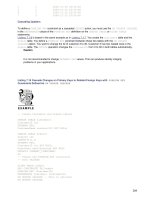
The following example reads the drawing instructions from a file and uses them to
display the graphic shown in Figure 12-10. Each line of the input text file contains an
opcode (
m for move and d for draw) and the coordinate point for the action to take
place. The file used in this example starts like this:
m 60 110
d 60 10
d 160 10
d 160 60
m 160 80
d 160 180
. . .
The first line is an instruction to move to the point (60,110). The second command
will draw a line from the pen’s position at (60,110) to a new location at (60,10).
Figure 12-10: A line drawing
defined in a file
4682-1 ch12.f.qc 11/13/00 14:12 Page 280
281
Chapter 12 ✦ Drawing and Painting with QPainter
1 /* drawvector.cpp */
2 #include <kapp.h>
3 #include <qpainter.h>
4 #include <stdio.h>
5 #include “drawvector.h”
6
7 int main(int argc,char **argv)
8 {
9 KApplication app(argc,argv,”drawvector”);
10 DrawVector drawvector;
11 drawvector.show();
12 app.setMainWidget(&drawvector);
13 return(app.exec());
14 }
15 DrawVector::DrawVector(QWidget *parent,const
16 char *name) : QWidget(parent,name)
17 {
18 setFixedSize(230,190);
19 }
20 void DrawVector::paintEvent(QPaintEvent *)
21 {
22 FILE *fd;
23 char code[20];
24 int x;
25 int y;
26
27 if((fd = fopen(“points.dat”,”r”)) != NULL) {
28 QPainter p(this);
29 while(fscanf(fd,”%s %d %d”,code,&x,&y) == 3) {
30 if(code[0] == ‘m’)
31 p.moveTo(x,y);
32 else if(code[0] == ‘d’)
33 p.lineTo(x,y);
34 }
35 fclose(fd);
36 }
37 }
All of the drawing is done in the loop on lines 28 through 34. Line 28 initializes
graphic operations by creating a
QPainter object for this widget. The call to
fscanf() on line 29 reads a line of input data—the command, the x coordinate,
and the y coordinate. If the command is to move the current cursor, the method
moveTo() is called on line 31. If the command is to draw a line from the current
cursor to this new location, a call is made to
lineTo() on line 33.
4682-1 ch12.f.qc 11/13/00 14:12 Page 281
282
Part II ✦ Step by Step
Line Segments and Polygons
Some QPainter methods allow you to store a set of points in a QPointArray object
and then use the points to draw polygons. The following program demonstrates
some of the different ways a collection of line segments can be drawn:
1 /* drawpoly.cpp */
2 #include <kapp.h>
3 #include <qpainter.h>
4 #include “drawpoly.h”
5
6 int main(int argc,char **argv)
7 {
8 KApplication app(argc,argv,”drawpoly”);
9 DrawPoly drawpoly;
10 drawpoly.show();
11 app.setMainWidget(&drawpoly);
12 return(app.exec());
13 }
14 DrawPoly::DrawPoly(QWidget *parent,const
15 char *name) : QWidget(parent,name)
16 {
17 setFixedSize(500,100);
18 }
19 void DrawPoly::paintEvent(QPaintEvent *)
20 {
21 int offset = 0;
22 QPointArray parray(10);
23 QPainter p(this);
24
25 setPoints(parray,offset);
26 p.drawLineSegments(parray);
27
28 setPoints(parray,offset += 100);
29 p.drawPolyline(parray);
30
31 setPoints(parray,offset += 100);
32 p.drawPolygon(parray);
33
34 p.setBrush(QColor(“white”));
35 setPoints(parray,offset += 100);
36 p.drawPolygon(parray,TRUE);
37
38 setPoints(parray,offset += 100);
39 p.drawPolygon(parray,FALSE);
40 }
41 void DrawPoly::setPoints(QPointArray &parray,int offset)
42 {
43 parray.setPoint(0,10+offset,50);
44 parray.setPoint(1,70+offset,50);
45 parray.setPoint(2,70+offset,30);
4682-1 ch12.f.qc 11/13/00 14:12 Page 282
283
Chapter 12 ✦ Drawing and Painting with QPainter
46 parray.setPoint(3,50+offset,30);
47 parray.setPoint(4,50+offset,90);
48 parray.setPoint(5,30+offset,90);
49 parray.setPoint(6,30+offset,10);
50 parray.setPoint(7,90+offset,10);
51 parray.setPoint(8,90+offset,70);
52 parray.setPoint(9,10+offset,70);
53 }
The setPoints() method on line 41 inserts the points into the array. The same set
of points is used for each drawing, as shown in Figure 12-11, except the horizontal
position is shifted to the right by the amount of the
offset.
Figure 12-11: Five ways to draw a polygon
The call to drawLineSegments() on line 26 draws the version of the polygon
shown on the far left of Figure 12-11. The lines are not joined together because
only line segments are drawn. That is, the first line is drawn between point[0] and
point[1], the second is drawn between point[2] and point[3], and so on. For every
line drawn, there must be two members in the array of points. Of course, you can
force the lines to join into a polygon by using the ending point of a line as the start-
ing point of the next.
The call to
drawPolyLine() on line 32 uses the same input information as draw
LineSegments()
, but it draws all the line segments by starting each new line seg-
ment at the point where the previous line segment left off. That is, the first line is
drawn between point[0] and point[1], the second is drawn between point[1] and
point[2], and so on. In the array of point data, the last point does not coincide with
the first point, so the polygon is not closed.
The call to
drawPolygon() on line 32 draws the figure in the same way as drawLine
Sgemetns()
, but it also draws a line from the end point back to the beginning,
resulting in a closed shape.
The call to
drawPolygon() on line 36 draws the shape after a QBrush has been
stored in the
QPainter object, and this results in the polygon being filled. Just as
with any of the other shapes, the area is filled before it is outlined, causing the out-
lining to appear on top of the fill. The second argument to the method call sets the
winding rule to
TRUE, which means that all areas of the polygon will be filled with-
out regard to overlaps of itself.
4682-1 ch12.f.qc 11/13/00 14:12 Page 283
284
Part II ✦ Step by Step
The call to drawPolygon() on line 39 is the same as the previous one, except the
winding rule is set to
FALSE. This setting means that the only regions of the poly-
gons that are filled are those covered with an odd number of layers. The rightmost
drawing in Figure 12-11 shows that the area where the shape overlaps itself is not
filled —that is, there are two layers of the shape at the overlap point. If the shape
were to overlap the same point with a third layer, it would be filled again.
Ellipses and Circles
The method drawEllipse() is used to render both circles and ellipses because
a circle is simply an ellipse with equal height and width. The following program
displays the window shown in Figure 12-12, containing two ellipses and a circle:
1 /* drawellipse.cpp */
2 #include <kapp.h>
3 #include <qpainter.h>
4 #include “drawellipse.h”
5
6 int main(int argc,char **argv)
7 {
8 KApplication app(argc,argv,”drawellipse”);
9 DrawEllipse drawellipse;
10 drawellipse.show();
11 app.setMainWidget(&drawellipse);
12 return(app.exec());
13 }
14 DrawEllipse::DrawEllipse(QWidget *parent,const
15 char *name) : QWidget(parent,name)
16 {
17 setFixedSize(260,140);
18 }
19 void DrawEllipse::paintEvent(QPaintEvent *)
20 {
21 QPainter p(this);
22
23 p.drawEllipse(10,50,110,40);
24 p.setBrush(QColor(“white”));
25 p.drawEllipse(130,25,90,90);
26 p.setPen(NoPen);
27 p.drawEllipse(230,10,20,120);
28 }
Figure 12-12: Two ellipses and a circle
4682-1 ch12.f.qc 11/13/00 14:12 Page 284
285
Chapter 12 ✦ Drawing and Painting with QPainter
The drawEllipse() method requires that you define a bounding box to specify the
four sides of the ellipse. The bounding box is defined by the
x and y coordinates of
its upper-left corner, and the width and height of the box. For example, the ellipse
on the left in Figure 12-12 is drawn by the call to
drawEllipse() on line 23, with its
upper-left corner 10 pixels from the left edge and 50 pixels from the top. The width
of the ellipse is 110 pixels and its height is 40 pixels.
A
QBrush object is added to QPainter by the call to setBrush() on line 24, so the
rest of the ellipses are filled with the brush color. Line 26 calls
setPen() to remove
the pen from
QPainter, so the ellipse on the right has no outline.
It may happen that you need to draw a circle or an ellipse around a center point
instead of the upper left corner. To do this, simply subtract the radius from the
center point (in each direction) to locate the upper-left corner:
p.drawEllipse(x - (w / 2),y - (h / 2),w,h);
Drawing Parts of Circles and Ellipses
There are three ways you can draw part of a circle or an ellipse. The process is the
same as drawing a circle or ellipse, as in the previous example, except you must
also specify a starting and ending angle.
To specify which part of the circle or ellipse is to be drawn, it is necessary to spec-
ify the starting and ending angles. The angles are measured in units of one-sixteenth
of a degree. If you are going to be entering hard-coded angles, Table 12-2 lists some
of the more commonly used values.
Table 12-2
Comparison of Angle Measurement Units
Qt Units Degrees Radians
00 0
720 45 0.7854
1440 90 1.5708
2160 135 2.3562
2880 180 3.1416
3600 225 3.9270
4320 270 4.7124
5040 315 5.4978
5760 360 6.2832
4682-1 ch12.f.qc 11/13/00 14:12 Page 285
286
Part II ✦ Step by Step
If you are going to be calculating the angles, most math software utilities use either
degrees or radians; you will need to convert back and forth. The following state-
ments will convert degrees and radians to the Qt scale:
angle = degree * 16;
angle = (radian * 180) / PI;
And these statements will convert Qt scale values to degrees and radians:
degree = angle / 16;
radian = (angle * PI) / 180;
Positive rotation is counterclockwise. The zero-degree point is on the right. The
starting and ending angles are expressed in relative terms. That is, the starting
angle specifies the distance from the zero point that the drawing is to begin, and
the ending angle specifies the distance from the starting angle to the end of the
drawing. Both numbers can be either positive or negative. If the starting angle is
less than the ending angle, the drawing occurs in the positive (counterclockwise)
direction. If the starting angle is less than the ending angle, the drawing occurs in
the negative (clockwise) direction.
The following example demonstrates three different approaches to drawing an arc:
1 /* arcpiechord.cpp */
2 #include <kapp.h>
3 #include <qpainter.h>
4 #include “arcpiechord.h”
5
6 int main(int argc,char **argv)
7 {
8 KApplication app(argc,argv,”arcpiechord”);
9 ArcPieChord arcpiechord;
10 arcpiechord.show();
11 app.setMainWidget(&arcpiechord);
12 return(app.exec());
13 }
14 ArcPieChord::ArcPieChord(QWidget *parent,const
15 char *name) : QWidget(parent,name)
16 {
17 setFixedSize(260,420);
18 }
19 void ArcPieChord::paintEvent(QPaintEvent *)
20 {
21 QPainter p(this);
22
23 p.drawArc(10,50,110,40,0,4000);
24 p.drawChord(10,190,110,40,0,4000);
25 p.drawPie(10,330,110,40,0,4000);
26 p.setBrush(QColor(“white”));
4682-1 ch12.f.qc 11/13/00 14:12 Page 286
287
Chapter 12 ✦ Drawing and Painting with QPainter
27 p.drawArc(130,25,90,90,0,2000);
28 p.drawChord(130,165,90,90,0,2000);
29 p.drawPie(130,305,90,90,0,2000);
30 p.setPen(NoPen);
31 p.drawArc(230,10,20,120,720,4320);
32 p.drawChord(230,150,20,120,720,4320);
33 p.drawPie(230,290,20,120,720,4320);
34 }
The call to drawArc() on line 23 creates the shape in the upper-left corner of Figure
12-13. This shape is drawn using the default
QPainter with a black pen and no
brush. The same bounding rectangle approach is used as is used with the ellipse.
That is, you choose the x and y coordinates of the upper-left corner of the bounding
box of the entire ellipse, even though you are only going to be drawing a portion of
it. The starting angle is 0 and the ending angle is 4000, which is almost 270 degrees.
Figure 12-13: Some ways to draw arcs,
pies, and chords
The call to drawArc() on line 27 creates the shape in the center of the first row of
Figure 12-13. Even though this figure is drawn with a
QPainter that has a brush,
there is no filling because an arc is not a closed figure. The call to
drawArc() on
line 31 does not appear because the pen has been disabled and
drawArc() does
not use the brush.
The call to
drawChord() on line 24 draws the leftmost shape in the center row of
Figure 12-13. A chord is like an arc, except that it always draws a line between the
end points of the arc to create a closed figure. Because a chord is a closed figure,
the calls to
drawChord() on lines 28 and 32 both fill the enclosed area with the
brush color.
4682-1 ch12.f.qc 11/13/00 14:12 Page 287
288
Part II ✦ Step by Step
The call to drawPie() on line 25 draws the leftmost shape of the bottom row of
Figure 12-13. A pie is like an arc, except that it always draws two lines between the
center and the two end points to create a closed figure. Because a pie is a closed
figure, the calls to
drawPie() on lines 29 and 33 both fill the enclosed area with the
brush color.
Rectangles with Rounded Corners
The QPainter method drawRoundRect() can be used to draw rectangles with
varying degrees of rounding on the corners. The following example demonstrates
the flexibility of
drawRoundRect(), which can be used to draw squares, rectangles,
circles, and ellipses as well as rounded-corner rectangles. The program draws a
number of shapes, as shown in Figure 12-14.
1 /* roundrectangle.cpp */
2 #include <kapp.h>
3 #include <qpainter.h>
4 #include “roundrectangle.h”
5
6 int main(int argc,char **argv)
7 {
8 KApplication app(argc,argv,”roundrectangle”);
9 RoundRectangle roundrectangle;
10 roundrectangle.show();
11 app.setMainWidget(&roundrectangle);
12 return(app.exec());
13 }
14 RoundRectangle::RoundRectangle(QWidget *parent,const
15 char *name) : QWidget(parent,name)
16 {
17 setFixedSize(190,370);
18 }
19 void RoundRectangle::paintEvent(QPaintEvent *)
20 {
21 QPainter p(this);
22 p.setBrush(QColor(“white”));
23
24 p.drawRoundRect(10,10,50,50);
25 p.drawText(30,35,”1”);
26
27 p.drawRoundRect(70,10,50,50,50,50);
28 p.drawText(90,35,”2”);
29
30 p.drawRoundRect(130,10,50,50,100,100);
31 p.drawText(150,35,”3”);
32
33 p.drawRoundRect(10,70,170,50);
4682-1 ch12.f.qc 11/13/00 14:12 Page 288
289
Chapter 12 ✦ Drawing and Painting with QPainter
34 p.drawText(90,95,”4”);
35
36 p.drawRoundRect(10,130,170,50,0,50);
37 p.drawText(90,155,”5”);
38
39 p.drawRoundRect(10,190,170,50,50,80);
40 p.drawText(90,215,”6”);
41
42 p.drawRoundRect(10,250,170,50,100,100);
43 p.drawText(90,275,”7”);
44
45 p.drawRoundRect(10,310,170,50,9,30);
46 p.drawText(90,335,”8”);
47 }
Figure 12-14: Some of the many forms
of rounded rectangles
Calling one of the following two methods draws a rounded rectangle:
drawRoundRect(int x,int y,int w,int h)
drawRoundRect(int x,int y,int w,int h,
int xround,int yround)
The first four arguments define a rectangle. The last two arguments (which both
default to 25) specify the roundedness of the corners in both the vertical and hori-
zontal directions.
Rectangle 1 in Figure 12-14 is drawn by the call to
drawRoundeRect() on line 24.
The first two arguments specify the x and y location of the upper left corner of
where the rectangle would be if it were not clipped off by being rounded. The figure
is a square that is 50 pixels on a side, and the roundedness of the corners was
4682-1 ch12.f.qc 11/13/00 14:12 Page 289
290
Part II ✦ Step by Step
allowed to default at 25 in both the x and y directions. This means that 25 percent
of the vertical distance and 25 percent of the horizontal distance will be used to
create the rounded corners.
Rectangle 2 is drawn by the call to
drawRoundedRect() on line 27. Like rectangle 1,
this call also produces a square, but the horizontal and vertical roundedness amounts
have been set to 50 percent each instead of being allowed to default to 25 percent.
Rectangle 3 demonstrates that setting the height and width to the same values, and
setting the roundedness to 100 percent, causes the entire length of the sides to be
included in the curved portion; the result is a circle.
Rectangle 4 is drawn on line 33. The vertical and horizontal roundedness are both
allowed to default to 25 percent, but because the rectangle is wider than it is tall,
more pixels are involved in the horizontal direction than in the vertical direction,
resulting in a curve that is not symmetrical.
Rectangle 5 is drawn on line 36 to demonstrate the fact that setting one (or both)
of the roundedness values to 0 percent will cause the corner to be square. In this
example, the vertical roundedness is set to 50 percent, but it cannot be used to
make a curve because the horizontal setting is 0 percent, which forces the horizon-
tal line to go all the way to the corner.
Rectangle 6 is created on line 39 by setting the vertical roundedness to 100 percent
and the horizontal roundedness to 30 percent.
Rectangle 7 is drawn on line 42 with both the horizontal and vertical roundedness
being set to 100 percent. The result is an ellipse.
Rectangle 8, drawn on line 45, is designed to have symmetrical roundedness— that
is, the same number of pixels are involved in the curve in both the vertical and hori-
zontal directions. Because roundedness is expressed as a percentage, it is necessary
to select a pixel value and then use it to determine the percent in each direction:
xround = (100 * pixels) / height;
yround = (100 * pixels) / width;
Drawing Pixmaps and Text
You can draw all or part of a pixmap and define the font to be used to draw any
text. The following example draws an entire pixmap, then part of a pixmap, and
then writes text on top of the drawing, as shown in Figure 12-15.
4682-1 ch12.f.qc 11/13/00 14:12 Page 290
291
Chapter 12 ✦ Drawing and Painting with QPainter
Figure 12-15: Pixmap with text
DrawPixmap Header
1 /* drawpixmap.h */
2 #ifndef DRAWPIXMAP_H
3 #define DRAWPIXMAP_H
4
5 #include <qwidget.h>
6
7 class DrawPixmap: public QWidget
8 {
9 public:
10 DrawPixmap(QWidget *parent=0,const char *name=0);
11 private:
12 QPixmap logo;
13 protected:
14 virtual void paintEvent(QPaintEvent *);
15 };
16
17 #endif
The QPixmap to be drawn is created from data, so it is only created once. It is
stored as
logo on line 12, so it will be available for display later.
DrawPixmap
1 /* drawpixmap.cpp */
2 #include <kapp.h>
3 #include <qpainter.h>
4 #include <qfont.h>
5 #include “drawpixmap.h”
6
7 #include “logo.xpm”
4682-1 ch12.f.qc 11/13/00 14:12 Page 291
292
Part II ✦ Step by Step
8
9 int main(int argc,char **argv)
10 {
11 KApplication app(argc,argv,”drawpixmap”);
12 DrawPixmap drawpixmap;
13 drawpixmap.show();
14 app.setMainWidget(&drawpixmap);
15 return(app.exec());
16 }
17 DrawPixmap::DrawPixmap(QWidget *parent,const
18 char *name) : QWidget(parent,name)
19 {
20 logo = QPixmap(magick);
21 setFixedSize(360,330);
22 }
23 void DrawPixmap::paintEvent(QPaintEvent *)
24 {
25 QPainter p(this);
26
27 p.drawPixmap(10,10,logo);
28 p.drawPixmap(250,80,logo,50,50,100,100);
29
30 QFont font = p.font();
31 font.setPointSize(18);
32 p.setFont(font);
33
34 p.setPen(QColor(“white”));
35 p.drawText(200,250,”Penguin”);
36 }
The constructor, beginning on line 17, creates the logo pixmap from the data file
logo.xpm included on line 7. It then sets the display window to a fixed size.
The call to
drawPixmap() on line 27 paints the entire logo pixmap. The upper-left
corner of the pixmap is located 10 pixels over and 10 pixels down from the upper-
left corner of the widgets. Because no other arguments were specified, the entire
pixmap is copied to the target location.
The call to
drawPixmap() on line 28 paints only a portion of the logo pixmap. This
method first extracts a rectangular area from the pixmap and then paints the extrac-
tion to the target window. The last four method arguments determine the extracted
area by specifying the upper left corner and the height and width. The area to be
extracted is 60 pixels from the left and 50 pixels from the top of the pixmap, its width
is 100 pixels, and its height is 80 pixels. The first two arguments specify where the
pixmap is to be drawn —its upper left corner is placed 250 pixels from the left and
80 pixels from the top.
4682-1 ch12.f.qc 11/13/00 14:12 Page 292
293
Chapter 12 ✦ Drawing and Painting with QPainter
Every QPainter object contains a QFont object that it uses to draw text. You can
use this default font, create a new font, or, as in this example, modify the existing
font. The call to
font() on line 30 retrieves the QFont object from the QPainter
object. In this example, a call is made to setPointSize() on line 31 to make the
text a bit larger. The call to
setFont() establishes the new font as the one that will
be used to paint all of
QPainter text.
See Chapter 10 for more information about creating and modifying fonts.
Line 34 calls setPen() to make the text appear as white (instead of the default
black), and the call to
drawText() on line 35 paints the text on the window, with
the left end of the text baseline 200 pixels from the left and 250 pixels from the top
of the window.
Summary
The QPainter methods described in this chapter should supply you with over 90
percent of the graphics you will ever need. With only two objects that render graph-
ics, a
QPen and a QBrush, you can create anything you want. If you need extreme
flexibility, you can use the pixel-by-pixel approach to get exactly what you want.
This chapter explored
QPainter methods that can be used to accomplish the
following:
✦ Draw one pixel at a time to the window, or define objects to hold arrays of
pixels and draw them all at once.
✦ Draw lines, in multiple colors and various widths, from any point to any other
point. Also, multisegmented lines can be drawn either one at a time or all at
once.
✦ Draw ellipses and circles in their entirety, or draw only a portion of the curve.
You can use different styles to fill and slice the circles and ellipses.
✦ Draw pixmaps —in their entirety or select a rectangular area.
The following chapter builds on the information in this chapter. Some methods in
the
QPainter object can be used to manipulate graphics to change their shape,
angle, and colors. You can also use some very specialized graphics objects to do
things like record a sequence of graphics commands for later playback.
✦✦✦
Cross-
Reference
4682-1 ch12.f.qc 11/13/00 14:12 Page 293
4682-1 ch12.f.qc 11/13/00 14:12 Page 294
Graphics
Manipulation
T
he previous chapter demonstrated some of the funda-
mentals of drawing and painting graphics to windows,
and this chapter demonstrates some of the special capabili-
ties in KDE and Qt for manipulating graphics.
Because everything displayed in a widget is graphic, many of
the techniques described in this chapter can be used to mod-
ify any graphic content. Probably the most useful information
pertains to the processes for rotating and positioning images,
but there is quite a bit more. For one thing, depending on the
capabilities of your printer, it is a very simple process to print
a graphic image in color or in black and white. It is possible
to reshape graphics scaling and shearing, or even to modify
images by making changes to bit values of each pixel. And ani-
mation can be performed by drawing one frame after another
and displaying the frames in a controlled, timed sequence.
Using a QPicture to Store Graphics
Anything that can be drawn to the window of a widget can
also be drawn to a
QPicture object. The QPicture object can
then save the drawing instructions to a disk file, and another
QPicture object can read the file and execute the drawing
instructions. There are a number of uses for this, including
the capability to store complicated drawings and transmit
graphics from one system to another. The following program
creates a simple drawing and saves it to a disk file:
Record
1 /* record.cpp */
2 #include <iostream.h>
3 #include <kapp.h>
4 #include <qpainter.h>
13
13
CHAPTER
✦✦✦✦
In This Chapter
Storing sequences of
graphic instructions
and playing them
back later for display
Printing windows and
other graphics
Querying the printer
for graphic
capabilities
Scaling, clipping,
shearing, rotating,
and translating
graphics
Animating sequences
of drawn shapes and
figures
Manipulating pixel
colors at the bit level
✦✦✦✦
4682-1 ch13.f.qc 11/13/00 14:12 Page 295
296
Part II ✦ Step by Step
5 #include <qpicture.h>
6 #include <qwidget.h>
7
8 int main(int argc,char **argv)
9 {
10 KApplication app(argc,argv,”record”);
11 QPainter paint;
12 QPicture pic;
13
14 paint.begin(&pic);
15 paint.setBrush(QColor(“black”));
16 paint.drawRect(50,75,350,100);
17 paint.setBrush(QColor(“white”));
18 paint.drawEllipse(150,50,150,150);
19 paint.setPen(QWidget::NoPen);
20 paint.drawRect(100,100,250,50);
21 paint.end();
22 if(!pic.save(“recplay.qpic”))
23 cout << “Unable to create recplay.qpic” << endl;
24 }
This program creates graphics, but does not display a window. Instead, it uses a
QPicture object as the target of the drawing, and the QPicture object records all
of the instructions and then writes them to a disk file.
On line 10, the
KAapplication object app is created to define this as a KDE appli-
cation because a
QPainter object can only be used inside a KDE application. Lines
11 and 12 create the
QPainter object that is used to do the drawing, and the
QPicture object that records the QPainter instructions.
Line 14 begins the graphics session by calling
begin(). The object of the drawing
is the
QPicture object, rather than a widget. Lines 15 through 20 set the QPainter
pen and brush values, and call the methods to do the actual drawing. The QPicture
object records each of these method calls. The drawing session is halted by the call
to
end() on line 21. The call to save() on line 22 creates the file named recplay.
qpic
that contains all of the drawing instructions.
Playback Header
1 /* playback.h */
2 #ifndef PLAYBACK_H
3 #define PLAYBACK_H
4
5 #include <qwidget.h>
6
7 class Playback: public QWidget
8 {
9 public:
10 Playback(QWidget *parent=0,const char *name=0);
11 protected:
12 virtual void paintEvent(QPaintEvent *);
13 };
4682-1 ch13.f.qc 11/13/00 14:12 Page 296
297
Chapter 13 ✦ Graphics Manipulation
14
15 #endif
Playback
1 /* playback.cpp */
2 #include <kapp.h>
3 #include <qpainter.h>
4 #include <qpicture.h>
5 #include “playback.h”
6
7 int main(int argc,char **argv)
8 {
9 KApplication app(argc,argv,”playback”);
10 Playback playback;
11 playback.show();
12 app.setMainWidget(&playback);
13 return(app.exec());
14 }
15 Playback::Playback(QWidget *parent,const
16 char *name) : QWidget(parent,name)
17 {
18 setFixedSize(450,250);
19 }
20 void Playback::paintEvent(QPaintEvent *)
21 {
22 QPainter p(this);
23 QPicture picture;
24
25 if(picture.load(“recplay.qpic”))
26 p.drawPicture(picture);
27 }
The paintEvent() method on line 20 creates a QPicture object to retrieve the
previously stored instructions. The call to
load() on line 25 retrieves the list of
instructions and, if the call to
load() is successful, the call to drawPicture() on
line 26 executes all of the instructions stored in the file. The result is the window
shown in Figure 13-1.
Figure 13-1: The playback of previously recorded
graphics commands
4682-1 ch13.f.qc 11/13/00 14:12 Page 297
298
Part II ✦ Step by Step
The previously recorded graphic instructions are painted using a QPainter object,
so there is nothing to prevent your program from embellishing the recorded instruc-
tions with some of your own. For example, the image shown in Figure 13-2 results
from changing the paint commands in the
paintEvent() method to the following:
if(picture.load(“recplay.qpic”))
p.drawPicture(picture);
p.setBrush(QColor(“black”));
p.drawRect(110,110,230,30);
Figure 13-2: Combining playback and current
graphics commands
Painting Graphics to a Printer
It is just as easy to paint pages on the printer as it is to paint windows on the display.
The following example program displays the same graphics window as the one previ-
ously shown in Figure 13-1, except for the addition of a Print button in the lower right
corner. Selecting the button will cause the dialog shown in Figure 13-3 to appear, allow-
ing the user to make decisions about the print. If the user selects the OK button, the
graphic is printed.
PrintGraphic Header
1 /* printgraphic.h */
2 #ifndef PRINTGRAPHIC_H
3 #define PRINTGRAPHIC_H
4
5 #include <qwidget.h>
6 #include <qpushbutton.h>
7
8 class PrintGraphic: public QWidget
9 {
10 Q_OBJECT
4682-1 ch13.f.qc 11/13/00 14:12 Page 298
299
Chapter 13 ✦ Graphics Manipulation
11 public:
12 PrintGraphic(QWidget *parent=0,const char *name=0);
13 private:
14 QPushButton *printButton;
15 private slots:
16 void printSlot();
17 protected:
18 virtual void paintEvent(QPaintEvent *);
19 };
20
21 #endif
PrintGraphic
1 /* printgraphic.cpp */
2 #include <kapp.h>
3 #include <qpainter.h>
4 #include <qprinter.h>
5 #include “printgraphic.h”
6
7 int main(int argc,char **argv)
8 {
9 KApplication app(argc,argv,”printgraphic”);
10 PrintGraphic printgraphic;
11 printgraphic.show();
12 app.setMainWidget(&printgraphic);
13 return(app.exec());
14 }
15 PrintGraphic::PrintGraphic(QWidget *parent,const
16 char *name) : QWidget(parent,name)
17 {
18 setFixedSize(450,250);
19 printButton = new QPushButton(“Print”,this);
20 printButton->setGeometry(370,200,70,40);
21 connect(printButton,SIGNAL(clicked()),
22 this,SLOT(printSlot()));
23 }
24 void PrintGraphic::paintEvent(QPaintEvent *)
25 {
26 QPainter paint;
27
28 paint.begin(this);
29 paint.setBrush(QColor(“black”));
30 paint.drawRect(50,75,350,100);
31 paint.setBrush(QColor(“white”));
32 paint.drawEllipse(150,50,150,150);
33 paint.setPen(QWidget::NoPen);
34 paint.drawRect(100,100,250,50);
35 paint.end();
36 }
37 void PrintGraphic::printSlot()
38 {
4682-1 ch13.f.qc 11/13/00 14:12 Page 299
300
Part II ✦ Step by Step
39 QPainter paint;
40 QPrinter printer;
41
42 if(printer.setup(this)) {
43 paint.begin(&printer);
44 paint.setBrush(QColor(“black”));
45 paint.drawRect(50,75,350,100);
46 paint.setBrush(QColor(“white”));
47 paint.drawEllipse(150,50,150,150);
48 paint.setPen(QWidget::NoPen);
49 paint.drawRect(100,100,250,50);
50 paint.end();
51 }
52 }
Figure 13-3: The user options that control printing
The constructor, on line 15, sets the size of the window and installs a button in the
lower right corner. The slot method
printSlot() is attached to the button.
The
paintEvent() method on line 24 draws graphics on the window of the widget.
The slot method
printSlot() on line 37 prompts the user for printer settings, and
if the user selects the OK button in the dialog shown in Figure 13-3, it draws the
graphics on a page of the printer. The call to
setup() on line 42 pops up the dialog,
4682-1 ch13.f.qc 11/13/00 14:13 Page 300
301
Chapter 13 ✦ Graphics Manipulation
and a return value of TRUE indicates that the print should proceed. Line 43 calls
begin() to attach the QPainter object to the printer. The graphics are then drawn
just as they would be if they were being drawn to the screen.
The call to
end() on line 50 ends the drawing and sends the graphics instructions
on to the printer. This call also closes the output to the printer and sends the page
(or pages) to the spooler for printing. If, in the middle of your printing, you wish to
eject the current page and start with a new one, you can do so with the following
method call:
print.newPage();
At any point during the printing process, you can delete all the pages before they
are sent to the spooler as follows:
print.abort();
Printer Information and Control
While it is just as easy to draw to a printer as it is to a window, you need to be able
to find out information about things like the size of the page and the number of dots
per inch. The following example program displays some of the basic printer infor-
mation in the window shown in Figure 13-4. You can run this program and use the
pop-up dialog to modify the printer settings and see the values change.
Figure 13-4: Some of the values describing a printer
PrintMetrics Header
1 /* printmetrics.h */
2 #ifndef PRINTMETRICS_H
3 #define PRINTMETRICS_H
4
4682-1 ch13.f.qc 11/13/00 14:13 Page 301