Transoesophageal Echocardiography study guide and practice mcqs phần 2 pot
Bạn đang xem bản rút gọn của tài liệu. Xem và tải ngay bản đầy đủ của tài liệu tại đây (133.29 KB, 14 trang )
1
Physics of ultrasound
Basic principles
Nature of ultrasound
Sound = longitudinal, mechanical wave
particles move parallel to direction of travel
Audible sound < 20 kHz
Ultrasound > 20 kHz
Sound cannot travel through a vacuum
Four acoustic variables
Density (g/l)
Pressure (kPa)
Temperature (K)
Particle motion (m)
Compressions: high density/pressure/temperature/motion +
Rarefactions: low density/pressure/temperature/motion
(Fig. 1.1)
Transthoracic echo (TTE) ∼ 2–5 MHz
Transoesophageal echo (TOE) ∼ 3.5–7 MHz
Sound is described by
Propagation speed (m/s)
Frequency (Hz)
Wavelength (m)
Physics of ultrasound
3
Table 1.1 Speed of sound in different media
Tissue Speed of sound (m/s)
Air 331
Lung 500
Fat 1450
Brain 1541
Liver 1549
Muscle 1585
Bone >3000
Frequency (f)
f = number of cycles per second Units = Hz
U/S > 20 kHz
Determined by sound source
Affects penetration and axial resolution
Period (T)
T = length of time to complete one cycle Units = s
U/S = 0.1–0.5 µs
Determined by sound source
Reciprocal of frequency T = 1/f
Wavelength (λ)
λ = distance occupied by a single cycle Units = m
U/S = 0.1–0.8 mm
Determined by sound source and medium
λ influences axial resolution
Velocity (v), frequency ( f ) and wavelength (λ) associated by the
equation
v = f λ
4 Transoesophageal Echocardiography
A
Amplitude
Peak-to-peak amplitude
Fig. 1.2
Amplitude
Fig. 1.3
Amplitude (A)
A = max. variation in acoustic variable Units = kPa, g/l, K, m, dB,
i.e. difference between
mean and max. values
(Fig. 1.2)
Decibel (dB) = logarithmic relative unit of measure of A
i.e. difference between two values
e.g. ↑ by 30 dB =↑Aby10× 10 × 10 (×1000)
Determined by sound source
Changed by sonographer
Amplitude decreases as sound wave travels = attenuation
(Fig. 1.3)
Power (P)
P = rate of work/rate of energy transfer Units = W
Physics of ultrasound
5
Two cycles/pulse ‘on’ ‘off’
Fig. 1.4
Determined by sound source
Changed by sonographer
P = A
2
Intensity (I)
I = concentration of energy/power in a sound beam
Units = W/cm
2
Determined by sound source
Changed by sonographer
U/S I = 0.1–100 mW/cm
2
I = P/area
Pulsed ultrasound
Pulse = collection of cycles travelling together
individual ‘cycles’ make up the ‘pulse’
‘pulse’ moves as one
‘pulse’ has beginning and end
Tw o components:
‘cycle’ or ‘on’ time
‘receive’ or ‘off’ or ‘dead’ time (Fig. 1.4)
Pulsed U/S described by:
pulse duration (PD)
pulse repetition frequency (PRF)
pulse repetition period (PRP)
6 Transoesophageal Echocardiography
PRP
PD ‘off ’
Fig. 1.5
spatial pulse length (SPL)
duty factor (DF)
Pulse duration (PD)
PD = time from start of one pulse to end of pulse Units = s
= ‘on’ time (Fig. 1.5)
Determined by:
number of cycles in a pulse (‘ringing’)
period of each cycle
Characteristic of transducer/not changed by sonographer
TOE PD = 0.5–3 µs
PD = number of cycles × T PD = number of cycles/ f
Pulse repetition frequency (PRF)
PRF = number of pulses per second Units = Hz
(Number of cycles per pulse not relevant)
Determined by sound source
Changed by sonographer by changing image depth
As image depth increases → PRF↓
Sonographer ↑‘dead’ time by ↑image depth =↓PRF
TOE PRF = 1–10 kHz
PRF(kHz) = 75/depth (cm)
Physics of ultrasound
7
Pulse repetition period (PRP)
PRP = time from start of one pulse to start of next pulse
Units = s
PRP = ‘on’ time (PD) + ‘off’ time (Fig. 1.5)
Changed by sonographer by changing ‘off’ time
TOE PRP = 0.1–1 ms
PRP (µs) = 13 × depth (cm)
Spatial pulse length (SPL)
SPL = length in distance occupied by one pulse Units = m
Determined by sound source and medium
Cannot be changed by sonographer
TOE SPL = 0.1–1 mm
Determines axial resolution
i.e. short SPL → better axial resolution
SPL = number of cycles × λ
Duty factor (DF)
DF = percentage of ‘on’ time compared to PRP Units = %
Changed by sonographer by changing ‘off’ time
TOE DF = 0.1–1% (i.e. lots of ‘off’/listening time)
DF = PD/PRP
↑DF by:
↑PRF (more pulses/s)
↑PD (by changing transducer)
↓DF by:
↑PRP (by ↑‘off’ time)
↑image depth
DF = 100% = continuous wave (CW) U/S
DF = 0% = machine off
8 Transoesophageal Echocardiography
Hi
g
h intensit
y
Low intensit
y
Fig. 1.6
Intensity
High intensity Low intensity
Fig. 1.7
Properties of ultrasound
Intensity (I)
Described by:
(1) Spatial – U/S beam has different I at different locations (Fig. 1.6)
Peak I = spatial peak (SP)
Average I = spatial average (SA)
(2) Temporal – U/S beam has different I at different points in time
(Fig. 1.7)
Peak I = temporal peak (TP), i.e. ‘on’ time
Average I = temporal average (TA), i.e. average of ‘on’ and ‘off’
For CW: TP = TA
(3) Pulse – U/S beam has average I for duration of pulse (‘on’)
= pulse average (PA)
Physics of ultrasound
9
Highest I SPTP
SPPA
SPTA
SATP
SAPA
Lowest I SATA
SPTA relevant to tissue heating
For CW: SPTP = SPTA and SATP = SATA
When PW and CW have same SPTP/SATP
CW has higher SPTA/SATA
PA > TA for PW
Beam uniformity ratio (BUR)
BUR = SP/SA factor
No units
Scale 1– ∞ (infinity)
Describes the spread of sound beam in space
TOE BUR = 5–50
Attenuation
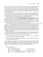
Decrease in A/P/I as sound wave travels (Fig. 1.3)
Units =−dB
In soft tissue: ↑f →↑attenuation
Three components:
(1) absorption:
energy transferred to cell in tissue by conversion to other form of
energy
sound → heat/vibration
(2) reflection:
energy returned to source when it strikes a boundary between two
media
10 Transoesophageal Echocardiography
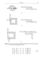
(i) Specular reflections
U/S Specular U/S with Specular
reflection
small SPL reflection
Smooth surface
Rough surface
(ii) Scatter
U/S with U/S with
high SPL SPL >> rbc
Scatter
Rayleigh
Rough surface
scattering
Fig. 1.8
(3) scatter:
sound beam hits rough surface → sound wave redirected in several
directions
Rayleigh scattering = when reflector << SPL (e.g. red blood cells)
→ scattering equal in all directions
(Fig. 1.8)
Attenuation coefficient (AC)
Units =−dB/cm
In soft tissue: ↑f →↑AC
AC = 0.5 × f (MHz)
Total attenuation = AC ×path length (cm)
↑AC in: bone (absorption and reflection)
air/lung (scatter)
Physics of ultrasound
11
Table 1.2 Effect of transducer frequency on attenuation
coefficient (AC) and half-value layer thickness (HVLT)
Transducer f (MHz) AC (−dB/cm) HVLT (cm)
213
3 1.5 2
421.5
5 2.5 1.2
631
Half value layer thickness (HVLT)
HVLT = depth at which I falls by
1
/
2
=−3dBUnits = cm
(also called penetration depth and half boundary layer)
TOE HVLT = 0.25–2 cm (Table 1.2)
HVLT = 3/AC HVLT = 6/ f
Impedance (Z)
Z = resistance to sound propagation Units = Rayls
Calculated/not measured
Soft tissue = 1.25–1.75 MRayls
Reflection depends upon change in Z between two media
(Fig. 1.9)
Z = ρ ×v (density × velocity)
Intensity reflection coefficient (IRC)
IRC (%) = reflected I /incident I
Intensity transmitted coefficient (ITC)
ITC (%) = transmitted I/incident I
Clinically: Soft tissue IRC = 1% ITC = 99%
Bone IRC = 99% ITC = 1%
With a 90
◦
incident angle, reflection only occurs if Z
1
= Z
2
Greater the difference between Z
1
and Z
2
→↑IRC
IRC (%) = [(Z
2
− Z
1
)/(Z
2
+ Z
1
)]
2
Physics of ultrasound
13
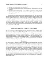
i
t
i
v
2
> v
1
when t > i v
1
> v
2
when i > t
v
1
v
1
v
2
v
2
sine t / sine i = v
2
/ v
1
t
Fig. 1.11
Transducers
Basic principles
Transducer (TX) = converts energy from one form to another
acoustic → kinetic → electrical → heat
Piezoelectric (P/E) effect
= ability of a material to create a voltage
when mechanically deformed
Reverse P/E effect = material changes shape when voltage applied
P/E materials = ferroelectric
Natural P/E materials
= quartz, Rochelle salts, tourmaline
Synthetic = Ba titanate, Pb titanate, Pb zirconate titanate (PZT)
U/S imagers – PZT-5 (also called ‘ceramic’)
Curie temperature
= temperature above which the P/E material
loses its P/E effect because it depolarizes
Therefore: TX cannot be heated/sterilized/autoclaved
14 Transoesophageal Echocardiography
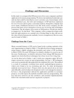
Matching layer
P/E crystal
Case/housing
Wire
Damping material
Fig. 1.12
Ultrasound transducers (Fig. 1.12) composed of:
(1) active element: P/E crystal (PZT-5)
(2) case:
protects internal components
insulates patient from electrical currents
(3) wire:
provides electrical contact with P/E crystal
voltage from U/S system → vibration → U/S wave
reception of signal → vibration → voltage to wire
(4) matching layer:
has impedance (Z) in-between that of TX and skin to prevent large
reflection at skin
Z of TX ≈ 33 MRayls
Z of skin ≈ 1.5 MRayls
→ 96% IRC at skin
Z of matching layer ≈ 7MRayls
Thickness of matching layer = λ/4
Improves axial resolution
(5) damping element:
material bonded to active element
epoxy resin impregnated with tungsten limits ‘ringing’
Improves axial resolution
Physics of ultrasound
15
‘Ringing’
= P/E crystals have prolonged response to excitation
→↑PD → reduced axial resolution
Length of ‘ringing’ response = ‘ringdown’
= number of half cycles required for oscillations of P/E crystal to decay
to 10% (−20 dB) of the max peak-to-peak amplitude
Damping →↓ringdown
→ absorbs U/S emitted from back face of TX, which causes
interference by reflecting within housing of TX
Transducer frequencies
Resonant f of TX depends on thickness of P/E crystal
Maxresonance occurs when thickness = λ/2
CW U/S: U/S f determined by and equal to f of voltage applied to P/E
crystal
PW U/S: PRF determined by number of electrical pulses the machine
delivers to P/E crystal
f of U/S determined by:
thickness (λ/2)
c in P/E crystal (∼ 4–6 mm/µs)
f (MHz) = c (mm/µs)/2 × thickness (mm)
Sound beams
Beam diameter:
starts same size as TX
converges to focus
diverges away from focus
Focus = location at minimum diameter (Fig. 1.13)
Focal depth (FD) = distance from TX to focus