AutoCAD Basics 2004 bible phần 7 pps
Bạn đang xem bản rút gọn của tài liệu. Xem và tải ngay bản đầy đủ của tài liệu tại đây (1.61 MB, 132 trang )
750
Part IV ✦ Drawing in Three Dimensions
Using DVIEW
To create a perspective view, type dview ↵ on the command line. At the Select
objects or <use DVIEWBLOCK>:
prompt, select the objects you want to include
in the process of defining the perspective view.
You should select as few objects as you need to visualize the final result if you have
a complex drawing. If you want to select the entire drawing, type all ↵ even if the
current view doesn’t display the entire drawing.
Press Enter if you don’t want to choose any objects. AutoCAD substitutes a block
called dviewblock, which is a simple house. You can use the house to set your per-
spective view.
If you want, you can create your own block and name it dviewblock. Create it with
X, Y, and Z dimensions of 1. When you press Enter at the Select objects or
<use DVIEWBLOCK>: prompt, AutoCAD looks for dviewblock and uses it to dis-
play the results of the perspective view settings.
Understanding the DVIEW options
DVIEW comes with a bewildering array of options that you use to specify the angle
and distance of the view. To use these options, start the DVIEW command and
select the objects you want to view or press Enter. You see the following prompt:
Enter option
[CAmera/TArget/Distance/POints/PAn/Zoom/TWist/CLip/Hide/Off/
Undo]:
You use these options to define the perspective view, as explained in the following
sections.
CAmera
Use the Camera option to specify the angle of the camera, which represents where
you are standing. You need to specify the angle from the X axis in the XY plane and
the angle from the XY plane. This is very similar to the way you specify a view using
the DDVPOINT command, explained earlier in this chapter.
When you choose this option, by right-clicking and choosing Camera, you see the
following prompt:
Specify camera location, or enter angle from XY plane, or
[Toggle (angle in)] <35.2644>:
Tip
539922 Ch22.qxd 5/2/03 4:13 PM Page 750
751
Chapter 22 ✦ Viewing 3D Drawings
The default angle is based on the current view when you start DVIEW. If you know
the angle from the XY plane, you can just type it in. You can also move the cursor
vertically to dynamically see the results. The view constantly changes as you move
the cursor, moving up over your objects as you move the cursor up, and down as
you move the cursor down. Move the cursor in one direction and then keep it still
for a second to see the full effect.
However, moving the cursor horizontally changes the angle from the X axis in the
XY plane. It can be confusing to change both angles at once so AutoCAD enables
you to limit the effect of your cursor movement to one angle. You do this with the
Toggle suboption.
Right-click and choose Toggle (angle in) to see the next prompt of the Camera
option:
Specify camera location, or enter angle in XY plane from X
axis, or [Toggle (angle from)]
<66.12857>:
Now, your cursor affects only the angle from the X axis. Move the cursor horizon-
tally to see your objects rotate around you at a constant altitude. Press Enter when
you like what you see, or you can type in an angle.
If you want to set the angle in the XY plane first and limit the effect of cursor
movement to that change, you need to use the Toggle suboption to get to the
Enter angle in XY plane from X axis: prompt. After you set the angle in
the XY plane, the suboption ends. Start the Camera option again to set the angle
from the XY plane.
TArget
The Target option (right-click and choose Target) works exactly like the Camera
option except that it defines the angles for the target of your viewpoint — what you
would see through the camera lens. However, the angles are relative to the camera
position. If you have already set the camera angles, the target angles default to
those created by drawing a straight line from the camera angle through 0,0,0. As
with the Camera option, use the Toggle suboption to switch between the two angles
you need to specify.
Distance
The Distance option is very important because using it turns on perspective mode.
Before you use this option, the views you see are parallel views. When you use
the Distance option, you see a slider bar at the top of the screen, as shown in
Figure 22-36. After you choose a distance, AutoCAD replaces the UCS icon with the
perspective mode icon if your UCS display is set to 2D. (Choose View➪ Display➪
UCS Icon ➪ Properties.)
Tip
539922 Ch22.qxd 5/2/03 4:13 PM Page 751
752
Part IV ✦ Drawing in Three Dimensions
Figure 22-36: Using the Distance option turns on perspective mode and
displays a slider bar.
AutoCAD displays the Specify new camera-target distance <3.0000>:
prompt. You can type a distance from the camera to the target or use the slider bar.
Move the cursor to the right to zoom out. Moving the cursor to 4x is equivalent to
using the ZOOM command and typing 4x ↵. Move the cursor to the left of 1x to
zoom in. The zoom factor is relative to the current display so that 1x leaves the
zoom unchanged.
You can also type a distance in drawing units.
POints
You can use the Points option (right-click and choose Points) to define the camera
and target. AutoCAD displays the
Specify target point <0.3776, -0.1618,
1.0088>:
prompt. The default target point, which is different for each drawing, is
the center of the current view. AutoCAD places a rubber-band line from the target
point, which you can use to get your bearings when choosing a new target point.
You can also type a coordinate. At the
Specify camera point <-1.5628,
0.9420, 2.2787>:
prompt, pick or type a point. AutoCAD keeps the rubber-band
line from the target so that you can visualize the camera and target points.
Because it is difficult to know what 3D points you are picking, you should use an
object snap or XYZ point filters to pick points.
539922 Ch22.qxd 5/2/03 4:13 PM Page 752
753
Chapter 22 ✦ Viewing 3D Drawings
While it is common to choose a target point on one of the objects in your drawing,
often you want the camera point to be off the objects so that you are looking at
the objects from a certain distance and angle. To pick the camera point, choose
Format
➪ Point Style (before starting DVIEW) and choose an easily visible point
style. Decide what elevation you want, type elev ↵ and set a new elevation. From
plan view, choose Point from the Draw toolbar and pick a point. The point is cre-
ated on the current elevation. Then use the Node object snap to snap to the point
when specifying the camera point in the Points option.
Even though the Points option sets both distance and angle for the camera and tar-
get points, you still need to use the Distance option to turn on perspective mode.
PAn
You cannot use the regular PAN or ZOOM commands within DVIEW, so DVIEW has
its own Pan and Zoom options. At the
Specify displacement base point:
prompt, pick any point. At the Specify second point: prompt, pick the point to
which you want the first point to pan. The model moves the distance and direction
indicated by an imaginary line from the base point to the second point.
Zoom
The Zoom option displays the same slider bar you see with the Distance option,
explained previously. If perspective mode is not on, you see the
Specify zoom
scale factor <1>:
prompt, which works like the Distance option slider bar. If
perspective mode is on, you see the
Specify lens length <50.000mm>: prompt.
A shorter lens length, such as 35mm, zooms you out, giving a wider angle view. A
longer lens length, such as 70mm, zooms you in, giving a narrower angle view.
Although the prompt shows a default in the form 50.000mm, you can only type in
a number. Omit the mm.
TWist
The Twist option turns your objects around in a circle parallel to the current view
you have defined. The default is zero (0) degrees, which is no twist. Assuming your
current view looks at the objects right side up, 180 degrees turns the objects upside
down, as if you had turned the camera in your hands upside down. AutoCAD dis-
plays a rubber-band line from the center of the view, which you can use to pick a
twist point, or you can type in an angle.
CLip
The Clip option enables you to create front and back planes that clip off the view.
Objects in front of the front clipping plane or behind the back clipping plane are not
displayed. You can use the front clipping plane to clip off a wall in front of the cam-
era, letting you see through the wall to the objects beyond—a kind of AutoCAD
X-ray vision. Use the back clipping plane when you want to exclude objects in the
Note
Tip
539922 Ch22.qxd 5/2/03 4:13 PM Page 753
754
Part IV ✦ Drawing in Three Dimensions
distance from your perspective view. The clipping planes are always perpendicular
to the line of sight, so you only need to set their distance from the target point.
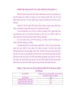
Compare Figure 22-37 to Figure 22-35. In Figure 22-37, the front posts and brackets
have been clipped so that they no longer obscure the rest of the model.
Figure 22-37: This model has a front clipping plane
that hides the front of the model. Compare it to
Figure 22-35.
When you choose the Clip option, you see the Enter clipping option
[Back/Front/Off] <Off>:
prompt. Specify Back or Front to set the back or front
clipping planes. Specify Off to turn off all previously defined clipping planes.
When you use the Distance option to create a perspective view, AutoCAD auto-
matically turns on a front clipping plane at the camera point.
When you specify the Front suboption, AutoCAD responds with the Specify
distance from target or [set to Eye(camera)/ON/OFF] <2.5682>:
prompt. Specify Eye to set the clipping plane at the camera point. You can define
the clipping plane by typing in a distance or using the slider bar that appears at
the top of your screen. As you move the cursor on the slider bar, stop to let the
drawing redraw so you can see the result.
When you specify the Back suboption, AutoCAD displays the
Specify distance
from target or [ON/OFF] <-5.5826>:
prompt. Specify On or Off to turn the
clipping plane on or off, or specify the distance as for the front clipping plane.
Hide
The Hide option performs a hide, just like the HIDE command, letting you clearly
see the results of the view you have created.
Note
539922 Ch22.qxd 5/2/03 4:13 PM Page 754
755
Chapter 22 ✦ Viewing 3D Drawings
Off
The Off option turns off perspective mode and returns you to a parallel view.
Otherwise, when you leave DVIEW after going into perspective mode, AutoCAD
retains the perspective view until you change the view—for example, with VPOINT.
Until then, you cannot pick points on the screen or use object snaps, which can be
very frustrating. This option enables you to exit from DVIEW in the normal viewing
mode.
Undo
The Undo option undoes the effect of the last DVIEW option. You can undo through
all the changes you have made in DVIEW.
The drawing used in the following Step-by-Step exercise on creating perspective
views, ab22-e.dwg, is in the Drawings folder of the AutoCAD 2004 Bible
CD-ROM.
Step-by-Step: Creating Perspective Views
1. Open ab22-e.dwg from the CD-ROM.
2. Save it as
ab22-03.dwg in your AutoCAD Bible folder. This is a portion of a
3D house in plan view, as shown in Figure 22-38. Make sure that OSNAP is on.
Set a running object snap set for endpoint and turn off any other object snaps.
3. You want to create a perspective view from approximately
1 to 2 in Figure
22-38. You can see right away that the wall near
1 will need clipping. To get
the distance of the clipping plane from the target, choose Tools ➪ Inquiry ➪
Distance and pick
3 and 4. The pertinent information is Distance = 12'-5
9/16"
. You may get a slightly different distance. To see the distance informa-
tion, press F2 to open the AutoCAD Text window.
4. Choose View ➪ 3D Views ➪ NE Isometric. The result is as shown in Figure
22-39. This is a quick approximation and helps you plan your camera and tar-
get points. To test for endpoints, start the LINE command. Place the cursor at
1 in Figure 22-39. The Endpoint SnapTip and marker appear. Place the cursor
at
2, the top of the table leg. You should see the Endpoint SnapTip and
marker. Press Esc to cancel the LINE command without drawing a line.
5. Type dview ↵. At the
Select objects or <use DVIEWBLOCK>: prompt,
type all ↵. Press Enter to end object selection.
6. At the main DVIEW prompt, right-click and choose Points. At the
Specify
target point <14'-5 15/16", 21'-9 3/8", 6'-1 1/4">:
prompt, pick
the endpoint at
2 in Figure 22-39. At the Specify camera point <14'-6
15/16", 21'-10 3/8", 6'-2 1/4">:
prompt, pick the endpoint at 1.
On the
CD-ROM
539922 Ch22.qxd 5/2/03 4:13 PM Page 755
756
Part IV ✦ Drawing in Three Dimensions
Figure 22-38: A 3D house in plan view
Thanks to Andrew Wilcox of Virtual Homes, Inc.,
Hammonds Plains, Nova Scotia, Canada, for this drawing.
I have used only a small portion of it.
Figure 22-39: The NE isometric view of the house
7. Right-click and choose Distance. At the Specify new camera-target dis-
tance <20'-10 15/16">:
prompt, move the cursor to 4x on the slider bar.
Take your hand off the mouse to let the drawing redraw until you can see the
result. Pick at the 4x mark. Notice the perspective view icon.
8. To move the camera point, right-click and choose Camera. At the
Specify
camera location, or enter angle from XY plane, or [Toggle
(angle in)] <11.7252>:
prompt, type 8 ↵ to lower the camera point
1
4
2
5
3
3
1
2
4
539922 Ch22.qxd 5/2/03 4:13 PM Page 756
757
Chapter 22 ✦ Viewing 3D Drawings
slightly. At the Specify camera location, or enter angle in XY
plane from X axis, or [Toggle (angle from)] <11.72523>:
prompt,
move the cursor close to
3 in Figure 22-39 relative to the screen, not the model
and click.
9. Right-click and choose Zoom. At the
Specify lens length <35.000mm>:
prompt, type 60 to zoom in slightly.
10. Right-click and choose Clip. Right-click and choose Front to set the front clip-
ping plane. At the
Specify distance from target or [set to Eye(cam-
era)] <83'-7 1/2">:
prompt, type 13' ↵. AutoCAD hides the front walls
that are blocking the view.
11. Right-click and choose Pan. At the
Specify displacement base point:
prompt, pick 4 in Figure 22-39 relative to the screen, not the drawing. At the
Specify second point: prompt, pick 5 relative to the screen. The display
moves down.
12. Right-click and choose Hide to hide the drawing. Your drawing should look
approximately like Figure 22-40.
13. Press Enter to end the DVIEW command.
14. After all that work, you should save the view. Choose View➪ Named Views. On
the Named Views tab, click New. In the New View dialog box, type Perspective
1 in the View Name text box. Click OK. Click OK to return to your drawing.
15. Save your drawing.
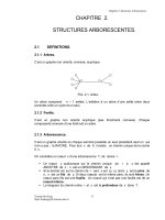
Figure 22-40: The final perspective view
539922 Ch22.qxd 5/2/03 4:13 PM Page 757
758
Part IV ✦ Drawing in Three Dimensions
Laying Out 3D Drawings
Laying out a 3D drawing on a layout tab is an important aspect of viewing a 3D
drawing, because the layout determines the final output of the drawing. AutoCAD
offers three commands that help you lay out your 3D drawing in paper space lay-
outs — SOLVIEW, SOLDRAW, and SOLPROF. You can find them on the Solids toolbar.
(Chapter 17 explains layouts.)
Flatten converts 3D polylines to 2D and flattens everything except blocks. Look in
\Software\Chap22\Flatten.
Using SOLVIEW to lay out paper space viewports
SOLVIEW automates the process of creating floating viewports and orthogonal
views — views at right angles from each other.
To start SOLVIEW, choose Setup View from the Solids toolbar. SOLVIEW has
five options:
✦ UCS enables you to choose the UCS to work from as well as set the scale, cen-
ter, and clipping corners of a floating viewport. Use this option first. After you
choose a UCS, type in a scale. You can change this later if you want. Then
SOLVIEW prompts you for the center of the view. Pick a point and wait until
the 3D model regenerates. SOLVIEW continues to prompt you for a view cen-
ter, letting you pick points until you like what you see. Press Enter to continue
the prompts. The clipping corners are the corners of the viewport. At the
Enter view name: prompt, type a name. SOLVIEW creates the first viewport.
Choose a view name that describes the view, such as Top, Side, or East
Elevation. This helps you when you start creating orthogonal views.
✦ Ortho creates orthogonal views. At the
Specify side of viewport to
project:
prompt, pick one of the edges of the first viewport. Again, choose a
view center and clip the corners to create the viewport. Type a name for this
new view.
If you don’t see the model properly when you pick the view center, continue
with the prompts, picking clipping corners where you want them. Then pick
the viewport (in model space with tile off) and do a Zoom Extents. You can
then pan and zoom as you want. This problem can happen when you have
several separate 3D objects in your drawing.
✦ Auxiliary creates inclined views. At the
Specify first point of
inclined plane:
prompt, pick a point in one of the viewports. At the
Specify second point of inclined plane: prompt, pick another point
in the same viewport. The two points are usually at an angle to create the
inclined view. At the
Specify side to view from: prompt, pick a point.
You then pick a view center and clipping corners, and specify a view name.
On the
CD-ROM
539922 Ch22.qxd 5/2/03 4:13 PM Page 758
759
Chapter 22 ✦ Viewing 3D Drawings
✦ Section creates cross sections. At the Specify first point of cutting
plane:
prompt, pick a point in a viewport. At the Specify second point
of cutting plane:
prompt, pick a point on the opposite side of the model
to create a cross section. You then pick a side to view from, and enter the view
scale, a view center, clipping corners, and a view name.
✦ eXit exits the command. (This option is not visible in the command prompt.)
You can exit the command after using an option and restart the command to
use another option, or you can use all the options and then exit the command
at the end.
Figure 22-41 shows an example with a top view, an orthogonal view from one side,
an auxiliary view, and a section.
Figure 22-41: An example of using SOLVIEW
Using SOLDRAW to create hidden lines and hatching
SOLDRAW uses the views created by SOLVIEW and creates 2D profiles that include
solid and hidden lines to represent the profiles and hatching for sectional views.
You must use SOLVIEW before using SOLDRAW.
To use SOLDRAW, choose Setup Drawing from the Solids toolbar. SOLDRAW
puts you into a paper space layout and prompts you to select objects, which
means floating viewports. You can select all of them if you want. SOLDRAW then
proceeds to automatically create the profile views. Figure 22-42 shows an example
of the hatching created for a sectional view.
539922 Ch22.qxd 5/2/03 4:13 PM Page 759
760
Part IV ✦ Drawing in Three Dimensions
Figure 22-42: The result of using SOLDRAW
on a sectional view
SOLDRAW uses hatch pattern defaults to define the hatch. You may have to change
these settings using HATCHEDIT.
SOLVIEW creates a whole set of new layers in your drawing. SOLDRAW freezes
your original layers, leaving visible only the layers needed to display the profile in
that paper space viewport. SOLVIEW creates a special layer that you can use for
dimensioning — one for each view that you create. For a view named front, the
layer is named front-dim. You can use these dimensioning layers to create dimen-
sions in paper space.
Using SOLPROF to create profiles
The SOLPROF command creates profiles like SOLDRAW, but you don’t need to
use SOLVIEW first. In addition, SOLPROF is more interactive than SOLDRAW. To
start the command, choose Setup Profile from the Solids toolbar. SOLPROF prompts
you to select objects.
When you start SOLPROF, you must have already created a floating viewport, and
you must be in model space.
At the Display hidden profile lines on separate layer? [Yes/No] <Y>:
prompt, type Y or N. By specifying Yes, you give yourself the capability of freezing
or turning off the layer containing hidden parts of the model. You can also hide
other 3D objects behind the one you are profiling.
At the
Project profile lines onto a plane? [Yes/No] <Y>: prompt, type
Y or N. If you choose Yes, SOLPROF creates 2D objects. If you choose No, SOLPROF
creates 3D objects.
At the
Delete tangential edges? [Yes/No] <Y>: prompt, type Y or N. A tan-
gential edge is the meeting of two contiguous faces. Most drafting applications do
not require you to show tangential edges.
Figure 22-43 shows the result of SOLPROF after freezing the layer containing the
original object — SOLPROF creates its own layers for the profile.
Note
Note
539922 Ch22.qxd 5/2/03 4:13 PM Page 760
761
Chapter 22 ✦ Viewing 3D Drawings
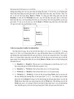
Figure 22-43: A profile created with
SOLPROF
Figure 22-44 shows the result of SOLPROF after also freezing the layer that SOL-
PROF created containing the hidden parts of the model. In this case, the layer was
named PH-159. Look for the h, which stands for hidden. The last part of the layer
name is the handle of the object you are profiling and so differs for each object.
Figure 22-44: A profile created with
SOLPROF after freezing the layer containing
the hidden parts of the model
You can combine viewports created with SOLPROF and viewports created with
SOLVIEW and SOLDRAW. For example, you can create two orthogonal views with
SOLVIEW and SOLDRAW and then add a viewport and use SOLPROF to create
another view.
As soon as you have a separate layer for the hidden portion of the model, you can
modify that layer’s color and/or linetype to show the hidden lines in a contrasting
color or linetype.
Tip
539922 Ch22.qxd 5/2/03 4:13 PM Page 761
762
Part IV ✦ Drawing in Three Dimensions
Summary
In this chapter, I covered all the ways to view your 3D drawing. You read about:
✦ Using the standard viewpoints on the Viewpoint flyout for a quick look
✦ Utilizing the DDVPOINT command to specify exact angles
✦ Using the tripod and compass for flexibility
✦ Using the PLAN command to quickly return you to plan view
✦ Shading your drawing in one of several modes — these shading modes persist
until you turn them off.
✦ Applying 3D orbit to view your model from any position. You can zoom and
pan, create parallel and perspective views, and set clipping planes. You can
also create a continuously moving orbit.
✦ Using the DVIEW command to let you create parallel and perspective views.
You set the camera and target where you can create front and back clipping
planes.
✦ Employing the three commands —SOLVIEW, SOLDRAW, and SOLPROF—that
help you lay out views of a 3D drawing for plotting
In the next chapter, I explain how to create 3D surfaces.
✦✦✦
539922 Ch22.qxd 5/2/03 4:13 PM Page 762
Creating 3D
Surfaces
I
n this chapter, you learn to create all types of surfaces,
also called meshes. Surfaces have a great advantage over
3D wireframe models because you can hide back surfaces and
create shaded images for easier visualization of your models.
Surfaces also enable you to create unusual shapes, such as for
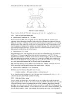
topological maps or free-form objects. Figure 23-1 shows a
lamp created by using surfaces.
Figure 23-1: A lamp created
with surfaces
You cannot obtain information about physical properties,
such as mass, center of gravity, and so on, from surfaces. Such
information can be obtained only from 3D solids, which are
covered in the next chapter.
23
23
CHAPTER
✦✦✦✦
In This Chapter
Drawing surfaces
with 3DFACE and
PFACE
Creating 3D polygon
meshes
Drawing standard 3D
shapes
Drawing a revolved
surface
Creating extruded,
ruled, and edge
surfaces
✦✦✦✦
28 539922 Ch23.qxd 5/2/03 9:40 AM Page 763
764
Part IV ✦ Drawing in Three Dimensions
AutoCAD approximates curved surfaces by creating a mesh of planes at varying
angles. You see the planes because AutoCAD displays them using a web of inter-
secting lines. AutoCAD defines the mesh by its vertices — where the lines intersect.
Figure 23-2 shows a mesh with its vertices.
Figure 23-2: A surface mesh
When working with surfaces you may want to display the Surfaces toolbar, shown
in Figure 23-3. Right-click any toolbar and choose Surfaces.
Figure 23-3: The Surfaces toolbar
Drawing Surfaces with 3DFACE
Two-dimensional objects are often used to create three-dimensional models. In
Chapter 21, I discuss how you can use 2D solids (the SOLID command), wide poly-
lines, and circles to make horizontal surfaces when you add a thickness to them. In
fact, the SOLID command is so useful in 3D that you can find its icon on the
Surfaces toolbar.
2D Solid
Box
Pyramid
Sphere
Dish
Edge
Revolved Surface
Ruled Surface
Wedge
3D Face
Cone
Dome
Torus
3D Mesh
Tabulated Surface
Edge Surface
28 539922 Ch23.qxd 5/2/03 9:40 AM Page 764
765
Chapter 23 ✦ Creating 3D Surfaces
You can also use regions in 3D drawings. While regions are 2D objects and cannot
be given a thickness, when you use the HIDE command, AutoCAD displays the
region as a surface. When the drawing is regenerated to a wireframe display, the
region is displayed as a wireframe again, losing its surface properties.
Another option is to use 3DFACE, which is a true 3D command. 3DFACE creates
three or four-sided surfaces that can be in any plane. You can place surfaces
together to make a many-sided surface. While AutoCAD draws lines between these
surfaces, you can make the lines invisible to create the effect of a seamless surface.
You define the surface by specifying the points that create the corners of the sur-
face. As a result, a 3D face cannot have any curves. 3DFACE only creates surfaces—
you cannot give a thickness to a 3D face. However, you can create a 3D solid from a
3D face using the EXTRUDE command. 3D solids are covered in the next chapter.
Using the 3DFACE command
To create a 3D face, choose 3D Face from the Surfaces toolbar. AutoCAD
prompts you for first, second, third, and fourth points. You must specify points
clockwise or counterclockwise, not in the zigzag fashion required by the 2D SOLID
command. When creating a 3D face:
✦ Press Enter at the
Specify fourth point or [Invisible] <create
three-sided face>:
prompt to create a three-sided surface. Then press
Enter again to end the command.
✦ To create a four-sided surface, specify a fourth point. AutoCAD repeats the
Specify third point or [Invisible] <exit>: prompt. Press Enter to
end the command.
✦ To create surfaces of more than four sides, continue to specify points.
AutoCAD repeats the third and fourth point prompts until you press Enter —
twice after a third point or once after a fourth point.
As you continue to add faces, the last edge created by the third and fourth points
becomes the first edge of the new face so that adding a face requires only two addi-
tional points.
It often helps to prepare for a complex 3D face by creating 2D objects for some or
all of the faces. You can then use Endpoint object snaps to pick the points of the
3D face. Place these 2D objects on a unique layer, such as Frames or Const.
Making 3D face edges invisible
Making edges invisible makes a series of 3D faces look like one 3D face. Figure 23-4
shows three 3D faces with and without internal seams.
You can control the visibility of 3D face edges in several ways.
Tip
28 539922 Ch23.qxd 5/2/03 9:40 AM Page 765
766
Part IV ✦ Drawing in Three Dimensions
Figure 23-4: You can make internal edges of a 3D
face invisible.
Controlling visibility during 3D face creation
While you are drawing the 3D face, you can right-click and choose Invisible before
each edge. Then specify the next point. However, it is sometimes difficult to predict
exactly where to indicate the invisible edge.
Using the EDGE command
After creating the entire 3D face, you can use the EDGE command. The sole purpose
of the EDGE command is to make 3D face edges visible and invisible — this is proba-
bly the easiest way to control the visibility of 3D face edges.
Choose Edge from the Surfaces toolbar. At the
Specify edge of 3dface to
toggle visibility or [Display]:
prompt, select a visible edge that you
want to make invisible. AutoCAD repeats the prompt so that you can select addi-
tional edges. Press Enter to make the edges invisible. Although a visible edge might
actually be two edges belonging to two adjacent 3D faces, EDGE makes them both
invisible.
To make invisible edges visible, right-click and choose the Display option. AutoCAD
displays all the edges in dashed lines and shows the
Enter selection method
for display of hidden edges [Select/All] <All>:
prompt. Press Enter to
display all the edges or use the Select option to select 3D faces (you can use win-
dows for selection). Either way, you see the edges of the 3D face you want to edit.
AutoCAD then repeats the
Specify edge of 3dface to toggle visibility
or [Display]:
prompt. You can now select the edge you want to make visible.
Press Enter to end the command and make the edge visible.
All edges visible
Internal edges invisible
28 539922 Ch23.qxd 5/2/03 9:40 AM Page 766
767
Chapter 23 ✦ Creating 3D Surfaces
Using the Properties palette
After creating one or more 3D faces, you can also open the Properties palette
(choose Properties on the Standard toolbar) and select one 3D face. (See
Figure 23-5.) You can choose more than one, but the results are difficult to predict.
Figure 23-5: You can use the Properties
palette to change the visibility of 3D face
edges.
Using this palette to edit 3D face edge visibility presents two difficulties. First, you
have no easy way to know which edge is which. The dialog box only labels them
Edge 1, 2, 3, and 4. Second, while the EDGE command makes both edges of adjacent
3D faces visible or invisible, the Properties palette does not. You need to use it for
each adjacent face. The best method is to use the EDGE command to control visibil-
ity of 3D face edges.
28 539922 Ch23.qxd 5/2/03 9:40 AM Page 767
768
Part IV ✦ Drawing in Three Dimensions
Using the SPLFRAME system variable
Setting the SPLFRAME system variable to 1 and then regenerating the drawing
makes all 3D face edges visible. (The SPLFRAME system variable also affects the
display of spline-fit polylines, hence its name.) To return edges to their original set-
ting, set SPLFRAME to 0 and do a REGEN.
The drawing used in the following Step-by-Step exercise on drawing 3D faces,
ab23-a.dwg, is in the Drawings folder of the AutoCAD 2004 Bible CD-ROM.
Step-by-Step: Drawing 3D Faces
1. Open ab23-a.dwg from the CD-ROM.
2. Save it as
ab23-01.dwg in your AutoCAD Bible folder. This is a blank draw-
ing with architectural units. Turn on ORTHO. OSNAP should be on. Set run-
ning object snaps for endpoints and midpoints. If the Surfaces toolbar is not
displayed, right-click any toolbar, and check Surfaces.
3. Choose 3D Face from the Surfaces toolbar. Follow the prompts:
Specify first point or [Invisible]: 6,6 ↵
Specify second point or [Invisible]: @20,0 ↵
Specify third point or [Invisible] <exit>: @0,2' ↵
Specify fourth point or [Invisible] <create three-sided
face>: @–20,0 ↵
Specify third point or [Invisible] <exit>: ↵
4. Start the COPY command. Follow the prompts:
Select objects: Select the 3D face.
Select objects: ↵
Specify base point or displacement, or [Multiple]: Right-
click and choose Multiple.
Specify base point: Pick any point.
Specify second point of displacement or <use first point as
displacement>: @0,0,1.5' ↵
Specify second point of displacement or <use first point as
displacement>: @0,0,3' ↵
Specify second point of displacement or <use first point as
displacement>: ↵
You don’t see any difference because you are looking at the three 3D faces in
plan view and they are on top of each other.
5. Choose View ➪ 3D Views ➪ SE Isometric. Your drawing should look like Figure
23-6. You now have the top, bottom, and the middle shelf of the cabinet.
6. Start the 3DFACE command again. Follow the prompts:
Specify first point or [Invisible]: Pick the endpoint at 1 in
Figure 23-6.
Specify second point or [Invisible]: Pick the endpoint at 2.
On the
CD-ROM
28 539922 Ch23.qxd 5/2/03 9:40 AM Page 768
769
Chapter 23 ✦ Creating 3D Surfaces
Specify third point or [Invisible] <exit>: Pick the endpoint
at 3.
Specify fourth point or [Invisible] <create three-sided
face>: Pick the endpoint at 4.
Specify third point or [Invisible] <exit>: Pick the endpoint
at 5.
Specify fourth point or [Invisible] <create three-sided
face>: Pick the endpoint at 6.
Specify third point or [Invisible] <exit>: Pick the endpoint
at 7.
Specify fourth point or [Invisible] <create three-sided
face>: Pick the endpoint at 8.
Specify third point or [Invisible] <exit>: ↵
Figure 23-6: The three 3D faces from an isometric
viewpoint
7. To draw the door of the cabinet, change the current layer to CONST. Start the
LINE command and draw a line from
2 in Figure 23-6 to @18<225. End the
LINE command. Now start the COPY command and copy the line from
2 to 1.
These two construction lines frame the door.
8. To make it easier to work on the door, choose Tools➪ New UCS➪3 Point.
Follow the prompts:
Specify new origin point <0,0,0>: Pick the left endpoint of
the bottom construction line.
Specify point on positive portion of X-axis <-0’-5 3/4”,-0'-6
3/4",0'-0">: Pick 1 in Figure 23-6.
Specify point on positive-Y portion of the UCS XY plane
<-0'-7 7/16",-0'-6",0'-">: Pick the left endpoint of the top
construction line.
4
7
6
3
2
5
8
1
28 539922 Ch23.qxd 5/2/03 9:40 AM Page 769
770
Part IV ✦ Drawing in Three Dimensions
9. Start the LINE command again. Follow the prompts:
Specify first point: Choose the From object snap.
Base point: Pick the left endpoint of the top construction
line.
<Offset>: @3,–3 ↵
Specify next point or [Undo]: Move the cursor to the right
and type 12 ↵.
Specify next point or [Undo]: Move the cursor down and type
30 ↵.
Specify next point or [Close/Undo]: Move the cursor to the
left and type 12 ↵.
Specify next point or [Close/Undo]: c ↵
Your drawing should look like Figure 23-7.
Figure 23-7: The partially completed cabinet
10. Change the current layer to 0. Choose 3D Face from the Surfaces toolbar.
Follow the prompts:
Specify first point or [Invisible]: Pick the endpoint at 1 in
Figure 23-7.
Specify second point or [Invisible]: Pick the endpoint at 2
in Figure 23-7.
Specify third point or [Invisible] <exit>: Pick the endpoint
at 3.
Specify fourth point or [Invisible] <create three-sided
face>: Pick the endpoint at 4 in Figure 23-7. Notice the edge
lines between 1 and 2 and between 3 and 4.
Specify third point or [Invisible] <exit>: Right-click and
choose Invisible. Pick the endpoint at 5 in Figure 23-7.
6
5
3
7
8
2
4
1
28 539922 Ch23.qxd 5/2/03 9:40 AM Page 770
771
Chapter 23 ✦ Creating 3D Surfaces
Specify fourth point or [Invisible] <create three-sided
face>: Pick the endpoint at 6.
Specify third point or [Invisible] <exit>: Right-click and
choose Invisible. Pick the endpoint at 7.
Specify fourth point or [Invisible] <create three-sided
face>: Pick the endpoint at 8.
Specify third point or [Invisible] <exit>: Pick the endpoint
at 1 in Figure 23-7.
Specify fourth point or [Invisible] <create three-sided
face>: Pick the endpoint at 9.
Specify third point or [Invisible] <exit>: ↵
11. Choose Edge from the Surfaces toolbar. At the Specify edge of
3dface to toggle visibility or [Display]:
prompt, pick the
edge between
1 and 2 and then the edge between 3 and 4. (A midpoint
marker and SnapTip appear.) Press Enter. The edges disappear.
12. Choose Tools ➪ New UCS➪ World.
13. Choose View ➪ 3D Views ➪ Viewpoint Presets to open the Viewpoint Presets
dialog box. Set the From: X Axis angle to 200 degrees. Set the XY Plane angle
to 35 degrees. Choose OK.
14. Choose View ➪ Hide to see the result. You can clearly see through the cabinet
door’s window.
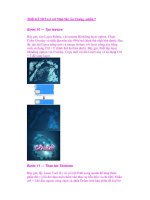
15. Save your drawing. It should look like Figure 23-8.
Figure 23-8: The completed kitchen cabinet,
including a window in the door
28 539922 Ch23.qxd 5/2/03 9:40 AM Page 771
772
Part IV ✦ Drawing in Three Dimensions
Drawing Surfaces with PFACE
PFACE draws surfaces called polyface meshes, which are a type of polyline.
However, you cannot edit them with PEDIT. The best way to edit them is with grips.
AutoCAD designed PFACE for the creation of surfaces using AutoLISP routines or
other automated methods. Consequently, the input for polyface meshes is some-
what awkward. However, polyface meshes have the following advantages:
✦ You can draw surfaces with any number of sides, unlike 3D faces, which can
only have three or four sides.
✦ The entire surface is one object.
✦ Sections that are on one plane do not show edges so that you don’t have to
bother with making edges invisible.
✦ You can explode polyface meshes into 3D faces.
✦ If you create a polyface mesh on more than one plane, each plane can be on a
different layer or have a different color. This can be useful for assigning mate-
rials for rendering or other complex selection processes.
On the other hand, polyface meshes are difficult to create and edit. Figure 23-9
shows two polyface meshes — one on one plane and the other on three planes.
Figure 23-9: You can create many-sided polyface meshes on one plane, or on
several different planes. After you use the HIDE command, the polyface mesh
hides objects behind it.
Eight-sided polyface
mesh on one plane
Polyface mesh
on three planes
28 539922 Ch23.qxd 5/2/03 9:40 AM Page 772
773
Chapter 23 ✦ Creating 3D Surfaces
The prompts for PFACE are divided into two phases. The first phase simply asks for
vertices. The second phase asks you to specify which vertex makes up which face
(or plane). The second phase is fairly meaningless for polyface meshes on one
plane, but you have to specify the vertices anyway. Here’s how to do it:
1. Type pface ↵.
2. At the
Specify location for vertex 1: prompt, specify the first vertex.
3. Continue to specify vertices at the
Specify location for vertex 2 or
<define faces>:
or Specify location for vertex 3 or <define
faces>:
prompts (and so on). Press Enter when you have finished.
4. At the
Face 1, vertex 1: Enter a vertex number or [Color/Layer]:
prompt, type which vertex starts the first face of the polyface mesh. It is usu-
ally vertex 1, so you type 1 ↵.
5. At the
Face 1, vertex 2: Enter a vertex number or [Color/Layer]
<next face>:
prompt, type which vertex comes next on the first face.
Continue to specify the vertices for the first face.
If you are drawing a polyface mesh on one plane, continue to specify all the
vertices in order and press Enter twice when you are done to end the com-
mand.
If you are drawing a polyface mesh on more than one plane, continue to spec-
ify the vertices on the first face (that is, plane) and press Enter. At the
Face
2, vertex 1: Enter a vertex number or [Color/Layer]:
prompt,
type the first vertex of the second face (plane) and continue to specify ver-
tices for the second face. Press Enter. Continue to specify vertices for all the
faces. Press Enter twice to end the command.
In order to easily draw a polyface mesh with PFACE, draw 2D objects as a guide for
picking vertices. Then you can use object snaps to pick the vertices. Also, for poly-
face meshes on more than one plane, draw a diagram that numbers the vertices.
This helps you specify which vertices make up which face.
During the second phase of the prompts, when PFACE asks you to define the faces,
you can right-click and choose Layer or Color and specify the layer or color. Then
specify the vertices that are to be on that layer or color.
In the following Step-by-Step exercise, you draw a hexagonal night table with poly-
face meshes.
The drawing used in the following Step-by-Step exercise on drawing polyface
meshes, ab23-b.dwg, is in the Drawings folder of the AutoCAD 2004 Bible
CD-ROM.
On the
CD-ROM
Tip
28 539922 Ch23.qxd 5/2/03 9:40 AM Page 773
774
Part IV ✦ Drawing in Three Dimensions
Step-by-Step: Drawing Polyface Meshes
1. Open ab23-b.dwg from the CD-ROM.
2. Save it as
ab23-02.dwg in your AutoCAD Bible folder. Two hexagons have
been drawn, one 24 inches above the other, on the Const layer, as shown in
Figure 23-10.
Figure 23-10: The two hexagons are the basis
for a night table.
3. Type pface ↵. Follow the prompts. First you specify all the vertices. Then you
specify the top hexagon, then the five sides (the front is open), and finally the
bottom hexagon. Unfortunately, if you make a mistake, you must start over.
Specify location for vertex 1: Pick 1 in Figure 23-10.
Specify location for vertex 2 or <define faces>: Pick 2in
Figure 23-10.
Specify location for vertex 3 or <define faces>: Pick 3.
Specify location for vertex 4 or <define faces>: Pick 4.
Specify location for vertex 5 or <define faces>: Pick 5.
Specify location for vertex 6 or <define faces>: Pick 6.
Specify location for vertex 7 or <define faces>: Pick 7.
Specify location for vertex 8 or <define faces>: Pick 8.
Specify location for vertex 9 or <define faces>: Pick 9.
Specify location for vertex 10 or <define faces>: Pick 0.
Specify location for vertex 11 or <define faces>: Pick !.
Specify location for vertex 12 or <define faces>: Pick @.
Specify location for vertex 13 or <define faces>: ↵
Face 1, vertex 1: Enter a vertex number or [Color/Layer]: 1 ↵
Face 1, vertex 2: Enter a vertex number or [Color/Layer]
<next face>: 2 ↵
Face 1, vertex 3: Enter a vertex number or [Color/Layer]
<next face>: 3 ↵
9
3
2
1
6
4
5
0
8
7
@
!
28 539922 Ch23.qxd 5/2/03 9:40 AM Page 774