Ethernet Networks: Design, Implementation, Operation, Management 4th phần 8 docx
Bạn đang xem bản rút gọn của tài liệu. Xem và tải ngay bản đầy đủ của tài liệu tại đây (508.8 KB, 60 trang )
408 chapter eight
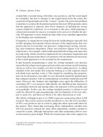
ISO OSI
Reference Model
IEEE 802.11 layers
Data
link
layer
Logical link control
Media access control (CSMA/CA)
Physical
layer
FHSS DSSS IR
Legend:
FHSS
DSSS
IR
Frequency Hopping Spread Spectrum
Direct Sequence Spread Spectrum
Infrared
Figure 8.1 IEEE 802.11 architecture.
several additions to the IEEE standard. One addition was the IEEE 802.11b
specification, which extended the operating rate of DSSS to 5.5 Mbps and
11 Mbps and which represented the most popular type of wireless LAN
when this book revision occurred. Both the basic 802.11 and the 802.11b
specifications operate in the 2.4 GHz unlicensed Industrial Scientific and
Medical (ISM) band. While the Federal Communications Commission (FCC)
in the U.S. regulates the maximum power and transmission method, the fact
that the ISM band is unlicensed means that a user does not have to obtain a
license to use equipment in that frequency band.
A second addendum to the IEEE 802.11 standard is the 802.11a specification.
This specification defines the use of a multi-carrier frequency transmission
method in the 5 GHz ISM band. The multi-carrier frequency method is referred
to as orthogonal frequency division multiplexing (OFDM), which results in
a large number of carriers being used, each of which operates at a low data
rate, but cumulatively they support a high data rate up to 54 Mbps. Because
higher frequencies attenuate more rapidly than lower frequencies, the range of
802.11a-compatible devices is significantly less than that of 802.11b devices.
This results in a requirement to install additional access points to obtain the
same area of wireless LAN coverage and increases the cost of a very high speed
wireless LAN. Because many network operators require more speed than that
wireless ethernet 409
provided by the 802.11b specification but a higher range than that supported
by the 802.11a specification, the IEEE has been working on a new standard,
referred to as 802.11g, which doubles the data rate of 802.11b networks to
22 Mbps in the 2.4 GHz frequency band.
Network Topology
The IEEE 802.11 wireless LAN standards support two types of network
topology, referred to as ad hoc and infrastructure. Figure 8.2 illustrates an
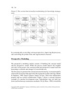
example of an ad hoc network. An ad hoc network consists of two or more
wireless nodes or stations that recognize one another and communicate on a
peer-to-peer basis within their area of RF or IR coverage. The term ‘‘ad hoc’’
is assigned as this type of network environment is commonly formed when
two wireless devices come into the range of one another and communicate on
a temporary basis until one or more devices depart the area.
A second type of wireless LAN topology is known as a network infrastruc-
ture. In its most basic form a wireless network infrastructure consists of an
access point (AP) connected to a wired LAN and one or more client stations.
Figure 8.3 illustrates an example of a wireless network infrastructure. In this
example an access point is shown connected to a hub on a wired LAN. The
access point can be considered to represent a bridge between the wired and
wireless LANs. However, in addition to providing bridging between the wired
and wireless networks, an access point also interconnects wireless clients.
That is, when an access point is present, client stations communicate with
one another through the AP and not on a peer-to-peer basis.
Station
Station
Station
Figure 8.2 A wireless ad hoc net-
work infrastructure.
410 chapter eight
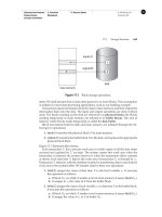
Client
station
Access
point
Basic service area
Wired hub/switch
Figure 8.3 A wireless network infrastructure contains at least one access
point and one wireless station, referred to as a Basic Service Set.
When two or more mobile nodes come together to communicate or if one
mobile client comes into close proximity to an access point, this action results
in the formation of a Basic Service Set (BSS). Each BSS has an identification
that typically corresponds to the 48-bit MAC address of the wireless network
adapter card. That identification is referred to as a Basic Service Set Identifi-
cation (BSSID) and the area of coverage within which members of a BSS can
communicate is referred to as a Basic Service Area (BSA).
When wiring an office, college campus or government agency, you will
more than likely need to install multiple access points. When this is done, the
basic service areas of coverage from multiple Basic Service Sets form what is
referred to as an Extended Service Set (ESS). The wired LAN infrastructure
functions as a distribution system, which enables clients to roam and be
serviced by different APs. Figure 8.4 illustrates an Extended Service Set
formed by the use of two access points interconnected by a wired LAN used
as a Distribution System (DS). Each BSS within a DS is said to be operating in
an infrastructure mode.
In examining Figure 8.4 it should be noted that the Basic Service Sets may
or may not overlap. In addition, each station associates itself with a particular
access point based upon selecting the one with the greatest received signal
strength. Each access point in the Extended Service Set will have an ESSID
(Extended Service Set Identifier) programmed into it. The ESSID can be
considered to represent the subnet the access point is connected to. You can
wireless ethernet 411
Access
point
Access
point
Hub
Hub
Hub
Client
BSS-1
BSS-2
Client Client
ESS
Server
Distribution
system
Legend:
BSS Basic Service Set
ESS Extended Service Set
Figure 8.4 An extended service set consists of one or more basic service sets
connected via a distribution system.
also program the ESSID into a station, which then requires it to connect to a
like programmed access point.
When creating an extended service set it is also important to consider
the frequency of operation of each access point. This is due to the need to
minimize the overlapping of frequency use by adjacent access points. Because
FHSS and DSSS operating access points have different restrictions concerning
frequency overlap, you must also consider the transmission scheme used
when you design a large wireless infrastructure.
Roaming
In examining Figure 8.4 note that the movement of a client from BSS-1 to BSS-
2 or vice versa represents a roaming action. Although IEEE 802.11 wireless
LANs support roaming, a wireless operational LAN environment is commonly
a fixed-location environment in comparison to cellular telephones, which are
used anywhere from a reception area, to the office, and even in the powder
room. Thus, while 802.11 wireless LANs support roaming, the actual degree
of this activity is limited in comparison to a cellular telephone.
412 chapter eight
As a mobile client moves from one access-point service area to another, a
mechanism is required for one AP to drop the user while the other begins
servicing the user. A mobile client will typically monitor the signal-to-noise
ratio (SNR) as it moves and, if required, scan for available access points
and connect to a desired AP. APs periodically transmit a beacon frame that
enables clients to note the presence of one or more APs and select the
one with the best SNR. However, the actual method used depends upon
a vendor’s implementation method. For example, in a Cisco wireless LAN
roaming environment a client will become associated with a new access point
when three conditions occur. First, the signal strength of the new access
point must be at least 50 percent. Second, the percentage of time the client’s
transmitter is active is less than 20 percent of the present access point. The
third condition requires the number of users on the new access point to be
four fewer than on the present access point. If the first two conditions are not
met, then the client will not change access points regardless of the number of
users associated with the AP.
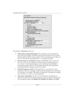
Physical Layer Operations
As discussed earlier in this chapter, the original IEEE 802.11 wireless LAN
standard supports a choice of three physical layers — infrared and two radio-
frequency layers. The infrared physical layer is based upon the use of pulse
position modulation (PPM) at peak data rates of 1 Mbps, with an optional
2 Mbps rate. Because infrared is limited to use within a single room without
barriers, its use is severely limited. In fact, this author is not aware of
any infrared-based 802.11 LANs. Because of this, in this section we will
focus our attention upon the RF physical layers. Both Frequency Hopping
Spread Spectrum (FHSS) and Direct Sequence Spread Spectrum operate in
the 2.4 GHz ISM band, which represents a worldwide-recognized unlicensed
band. However, it should be noted that the actual frequencies for the 2.4 GHz
band can vary from country to country, as noted in Table 8.1.
FHSS
Under Frequency Hopping Spread Spectrum data is transmitted for a short
duration, referred to as dwell time at a single frequency. At the end of that time
duration the transmitter shifts to a new frequency and resumes transmission.
Thus, a FHSS system uses narrow-band data transmission but changes its
frequency periodically to create a wide-band transmission system.
Figure 8.5 illustrates an example of how an FHSS system hops for predefined
time intervals using different center frequencies based upon a predefined
wireless ethernet 413
TABLE 8.1 2.4 GHz ISM Frequency Allocation
Region Allocated Frequency
United States 2.400–2.4835
Europe (except France/Spain) 2.400–2.4835
Japan 2.4710–2.4970
France 2.4465–2.4835
Spain 2.4450–2.4750
Time
f
5
f
3
f
2
f
1
f
0
f
4
Frequency
Figure 8.5 A frequency hopping spread spectrum system hops at a fixed time
interval, known as the dwell time, around a wide band using different center
frequencies in a predefined sequence.
algorithm. By only dwelling at one frequency for a short time duration,
an FHSS system can alleviate the effect of narrow-band noise occurring in
portions of the transmission band.
Although a military system based upon FHSS keeps the algorithm used
for hopping a secret, in the wonderful world of wireless LANs the hopping
sequence is well known. In fact, both the frequencies at which hopping occurs
as well as the number of hops within an assigned ISM band are commonly
414 chapter eight
regulated to prevent a wireless LAN from interfering with other electronic
equipment. In the United States FHSS uses 79 channels, each 1 MHz wide. In
Japan, the number of channels is reduced to 23. For both locations channels
are selected according to a pseudo-random selection algorithm that requires
a dwell time of 20 ms per channel and all channels to be used prior to being
able to reuse a channel. Under the IEEE 802.11 standard 78 different hopping
sequences are defined. Each hopping sequence is referred to as a channel,
which can cause a degree of confusion if you scan the standard without
noting this relationship. At the physical layer FHSS uses two- or four-level
Gaussian Frequency Shift Keying (GFSK) modulation. Under two-level FSK
modulation each bit is encoded by the transmission of a distinct frequency
from two available frequencies. Thus, the bit rate is the same as the baud
or signaling rate and the 1 MHz bandwidth used for each short transmission
supports a data rate of 1 Mbps. When four-level GFSK is used, each pair (dibit)
of bits is encoded into one of four frequencies. Thus, the bit rate is twice the
baud rate, resulting in a data rate of 2 Mbps. The term ‘‘Gaussian’’ prefixes
FSK because the wave form is Gaussian filtered.
Now that we have an appreciation for FHSS let us turn our attention to how
DSSS operates.
DSSS
Under Direct Sequence Spread Spectrum (DSSS) a spreading code is used
to spread each bit to be transmitted such that a number of bits representing
each bit are actually transmitted. The spreading code used under the 802.11
standard is referred to as a Barker code and its use results in each bit being
replaced by 11 bits. At 1 Mbps Differential Binary Phase Shift Keying (DBPSK)
is used for modulation, resulting in each bit being represented by one of two
possible phase changes. Because 11 bits replace each data bit, the resulting
signal is spread over 11 MHz. At 2 Mbps Differential Quadrature Phase Shift
Keying (DQPSK) is employed as the modulation method, which results in
two bits being encoded into one phase change. When this modulation method
is used, the bit rate becomes twice the baud rate, which results in a 2 Mbps
data rate.
Table 8.2 gives an example of DSSS coding using a five-bit sequences from
a pseudo-random bit generator. Note that data for transmission is simply
logically modulo-2 added to obtain the data stream to be modulated.
Upon demodulation the same pseudo-random bit sequence is modulo-2
subtracted to obtain the original setting of the bit that was spread. If a
transmission error occurs, the receiver simply selects the most popular bit
wireless ethernet 415
TABLE 8.2 DSSS Bit Spreading Example using a Five-bit
Spreading Code
Data bits 1 0
Five-bit spreading code 10110 01001
Modulo-2 addition (data to be modulated) 01001 01001
Demodulated data 01001 01001
Five-bit spreading code 10110 01001
Modulo-2 subtraction 11111 00000
setting. That is, a if a five-bit spreading code was used and as a result of the
modulo-2 subtraction process at the receiver, three bits were set to a value of
1 while two were set to a value of 0, the bit setting would be assumed to be 1.
Similar to FHSS, the use of DSSS can vary by location. Under the IEEE
802.11 standard the use of 13 DSSS channels is defined for transporting
an 11-bit Barker-coded 22 MHz signal. For operation in the United States
the 802.11 standard defines the use of 11 independent channels. Although
Europe and many Asian countries permit the use of 13 channels, in Japan the
small amount of available bandwidth (see Table 8.1) results in the support of
a single channel. Table 8.3 lists the carrier-frequency channel assignments.
As previously noted, depending upon the physical location of a DSSS system
a subset of available channels may be required to be used.
In the United States and Europe DSSS channel definitions permit three
frequency-isolated channels available for co-location. An example of chan-
nel co-location is illustrated in Figure 8.6. This frequency isolation enables
organizations to operate up to three DSSS functioning access points within
close proximity to one another without one access point interfering with
another.
High-Speed Wireless LANs
There are two extensions to the basic IEEE 802.11 standard for which equip-
ment had reached the market when this book revision was performed. Those
extensions are the IEEE 802.11b specification, for which equipment conform-
ing to that standard dominates the market, and the IEEE 802.11a specification.
Although the modulation methods differ for each method, they use the same
416 chapter eight
TABLE 8.3 2.4 GHz DSSS
Channels
Channel Frequency (MHz)
1 2412
2 2416
3 2422
4 2427
5 2432
6 2437
7 2442
8 2447
9 2452
10 2457
11 2462
12 2467
13 2473
2.4 GHz Frequency 2.4835 GHz
Figure 8.6 DSSS supports up to three non-overlapping channels in the
2.4 GHz band.
access protocol, a topic we will focus our attention upon once we obtain an
appreciation of the two extensions to the basic IEEE 802.11 standard.
802.11b
Under the 802.11b extension to the IEEE 802.11 standard the data rate was
increased to 5.5 Mbps and 11 Mbps under DSSS operations. At the higher data
wireless ethernet 417
rates of 5.5 Mbps and 11 Mbps DSSS transmitters and receivers use different
pseudo-random codes. Collectively, the higher modulation rates are referred
to as Complementary Code Keying (CCK).
802.11a
Under the 802.11a extension to the IEEE 802.11 standard orthogonal frequency
division modulation (OFDM) is employed in the 5 GHz frequency band. Under
OFDM multiple-modulated carriers are used instead of a single carrier, as
illustrated in Figure 8.7. Here each modulated signal is orthogonal to the
other modulated signals.
The term orthogonal describes the axis of the signals and the fact that they do
not interfere with one another. Because multiple signals are transmitted by a
single user, the carriers can be said to be multiplexed. Thus, the transmission
of multiple carriers at 90 degree angles to one another was given the term
OFDM. However, if you are familiar with the operation of DSL modems or
one of the first 9600 BPS analog dial modems, you are also probably aware of
the term ‘‘multitone’’ used to denote the use of multiple carriers. Thus, OFDM
can be considered to represent a multitone transmission scheme.
Under the 802.11a standard 48 data and four pilot carriers or a total of
52 carriers are transmitted within a 20 MHz channel. This action makes use
of the three blocks or bands of frequency allocated by the FCC for unlicensed
operations in the 5 GHz band. A 200 MHz band from 5.15 GHz to 5.35 MHz
has two sub-bands. The first 100 MHz in the lower section is restricted to a
maximum power output of 50 mW, while the second 100 MHz has a more
generous 250 mW maximum power output. A third band at 5.725 MHz to
5.825 MHz is designed for outdoor applications and supports a maximum of
1 W of power output.
Because the 5 GHz band has almost four times the bandwidth of the ISM
band, the developers of the 802.11a specification turned to OFDM to make
Frequency
Power
Figure 8.7 Orthogonal frequency division multiplexing results in the trans-
mission of multiple carriers, each modulating a small amount of data.
418 chapter eight
better use of available bandwidth. As previously mentioned, each 20 MHz
channel consists of 48 data subchannels and four used for pilot tones and
error correction, with each subchannel approximately 300 kHz wide.
Several different modulation methods are supported under the 802.11a
standard. Binary Phase Shift Keying (BPSK) is used to encode 125 kbps of
data per channel, resulting in a 6 Mbps data rate. When Quadrature Phase Shift
Keying (PSK) is used, the amount of data encoded increases to 250 kbps per
channel, which results in a 12 Mbps data rate. A 16-level quadrature amplitude
modulation method that encodes four bits per signal change permits a data
rate of 24 Mbps. At the ‘‘top end of the line’’ a 64-level QAM modulation
method is supported. 64 QAM can operate encoding either 8 or 10 bits per
signal change, permitting a maximum data rate of 1.125 Mbps per 300 Hz
channel. Because 48 data subchannels are supported per channel, this results
in a maximum data rate of 54 Mbps.
Although the 802.11a specification supports a much higher data rate than
the 802.11b specification, it is important to remember that higher frequencies
attenuate much more rapidly than lower frequencies. As a result of this, the
range of 802.11a equipment is probably half that of 802.11b products, which
means the radius of coverage of an 802.11a access point will be one-fourth
that of an 802.11b access point.
Access Method
Unlike wired Ethernet, which uses the CSMA/CD access protocol, wireless
Ethernet LANs use what is referred to as a distributed coordination func-
tion (DCF). DCF represents a modification of the Carrier Sense Multiple
Access/Collision Avoidance (CSMA/CA) protocol. Under the CSMA/CA pro-
tocol each station listens to the air for activity of other users. If the channel
it is tuned to is idle, the station can transmit. However, if the channel has
activity, the station will wait until transmission ceases and then enter a ran-
dom back-off procedure. This action is designed to prevent multiple stations
from seizing the channel immediately after the completion of an in-progress
transmission. Under the distribution coordination function access method a
period of time referred to as the DCF interframe space (DIFS) determines if
a packet can be transmitted. That is, if the medium is sensed to be available
for a duration of time that exceeds the DIFS, a packet can be immediately
transmitted.
A second time interval that comes into play under the DCF access method is
the short interframe space (SIFS). Under the IEEE 802.11 standard a receiver
must transmit a positive acknowledgement (ACK) to the transmitter when a
wireless ethernet 419
packet is received error free. An ACK will be transmitted after the SIFS, which
is of less duration than the DIFS. This ensures that an ACK is transmitted
prior to any new frame being transmitted. If an ACK is not received within a
period of time, the transmitter will assume the frame was corrupted and will
re-transmit the frame at the first opportunity to do so.
Figure 8.8 illustrates the relationship of the DIFS and SIFS to the transmis-
sion of data. At the top of the illustration the transmitting device is assumed
to listen to the channel and observe no activity for at least one DCF Interframe
Space (DIFS) prior to transmitting a frame. The receiving device must then
wait one Short Interframe Space (SIFS) prior to acknowledging the frame.
A second device requiring the ability to transmit is shown in the lower
portion of Figure 8.8. This device is assumed to need to transmit a frame,
but listens to the channel and hears the transmission of the first device or
the acknowledgement of the receiver. The time from the frame being placed
onto the channel through the DIFS following the receiver’s ACK represents a
deferred access time. Because a transmission was sensed to be in progress, the
second device must wait a random period after the deferred access time. The
second transmitter sets an internal time to an integer number of slot times and
observes when the DIFS time expires. Upon the expiration of the DIFS time
the timer of the second transmitter decrements towards zero. If the channel
is still available when the timer decrements to zero, the second station can
DataDIFS
DIFS
SIFS
ACK
Deferred access
Time
Contention
window
Next
data
Slot times
Back off
After defer
Transmitting
station A
Transmitting
station C
Receiving
station B
Legend:
DIFS DFC Interframe Space
SIFS Short Interframe Space
Figure 8.8 The CSMA/CA access protocol is based upon two key timers and
a back-off algorithm.
420 chapter eight
commence transmission. Otherwise, if the channel is used by another station
prior to the timer reaching zero, its setting is retained at its current value for
future use.
The Hidden Node Problem
Because radio-frequency communications can be easily blocked by obstruc-
tions, it becomes possible for one node to be placed in a situation where it
doesn’t hear another. When this situation occurs, another node would listen
to a channel and an obstruction hiding the transmission of another station
would make the node think it is available for use when it is actually occupied.
The result of this action would be a propagation of two radio waves that at
a distant point collide, preventing other nodes from using the channel. To
reduce the probability of collisions, a derivative of the CSMA/CA protocol
referred to as Virtual Carrier Sense (VSC) is used by the 802.11 standard.
Under VCS a station that needs to transmit information will first transmit a
Request to Send (RTS) frame. The RTS frame represents a relatively short con-
trol frame that contains the source and destination address and the duration
of the following transmission. The duration is specified in terms of the time
for the transmission of a frame carrying data and the acknowledgement of the
frame by the receiver. The receiver responds to the RTS frame with a Clear To
Send (CTS) control frame that indicates the same time duration information
as contained in the RTS control frame.
A station that receives either an RTS or CTS control frame will set its virtual
carrier sense indicator for the duration of the transmission. The VSC indicator
is referred to as the Network Allocation Vector (NAV) by the 802.11 standard
and serves as a mechanism to alert all other stations on the air to back off or
defer their transmission.
If a station transmitting an RTS frame does not receive a corresponding
CTS frame within a predefined period of time, the originator will assume a
collision has occurred. Then, the originator will listen to the channel and,
upon noting it is free, transmit another RTS frame. Once a CTS frame is
received, the originator will send a data frame. The receiver will then return
an ACK frame to acknowledge a successful transmission.
The use of RTS and CTS frames, while reducing the probability of collisions
occurring at a receiver from a station ‘‘hidden’’ from the transmitter, adds
overhead to the media access operation. Due to this, most manufacturers
disable this option by default, requiring network managers to enable it on
both client stations and access points.
wireless ethernet 421
8.2 Frame Formats
Similar to wired Ethernet, where there is one basic frame format, wireless
LANs also have a basic data frame format. However, wireless LANs also
support two additional types of frames. One type, referred to as control
frames, was briefly mentioned when we discussed the hidden node. The third
type of frame supported by wireless LANs is management frames, which are
used to exchange management information between stations at layer 2 but
which are not forwarded to upper layers in the protocol suite.
Data Frame
Figure 8.9 illustrates the format of the MAC data frame which is used to
transmit information between stations. This basic data frame contains nine
fields, with two fields subdivided into additional fields. As we will note later
in this section, several fields from this frame are used in other types of frames.
In examining Figure 8.9, you will note that the 802.11 frame permits a
body that can be up to 2312 bytes in length. Because the maximum length
Ethernet frame has a 1500-byte Information field, the wireless LAN frame
can transport a maximum wired Ethernet frame. However, because the bit
error rate on a radio link can considerably exceed that of a wired LAN, this
Frame
control
Duration/
ID
Address
1
Address
2
Address
3
Address
4
Sequence
control
Frame
body
CRC
Fragment
number
Sequence
number
Bytes
22 6 66 2 60−2312 6
Protocol
version
Type Subtype
To
Ds
From
Ds
More
frag
Pwr
Mgt
More
data
WEP RsvdRetry
22411111111
Figure 8.9 The basic 802.11 MAC data frame format.
422 chapter eight
means that the probability of a bit error increases as the length of the wireless
frame increases. To compensate for this higher wireless bit error probability,
a simple fragmentation and re-assembly mechanism is included in the 802.11
standard and we will shortly examine this. To obtain an appreciation of the
manner by which the MAC data frame conveys information, let us turn our
attention to the use of the fields and subfields in the frame.
Control Field
The 16-bit control field consists of 11 subfields, with eight representing one-
bit fields whose setting indicates whether a specific feature or function is
enabled or disabled. In this section we will examine the use of each subfield
in the order they appear in the control field.
Protocol Version Subfield
The two-bit Protocol Version subfield provides a mechanism to identify the
version of the IEEE 802.11 standard. In the initial version of the standard the
value of the Protocol Version subfield is set to 0.
Type and Subtype Subfields
The Type and Subtype subfields consist of six bits that identify the type of
frame and its function or subtype. Bits 2 and 3 denote the type of frame.
Although the use of two bits permits four types of frames to be defined,
at the present time only three types are defined — management, control,
and data. The Subtype subfield consists of bits 4 through 7 and defines the
function of a specific type of frame. Table 8.4 lists the Type and Subtype
subfield values to include a description of what the values of the y-bit
positions indicate.
In examining the entries in Table 8.4 note that the previously mentioned
RTS, CTS and ACK functions represent the frames we briefly described earlier
and the format of which we will investigate later in this section. The Beacon
frame represents the frame an access point periodically generates to indicate
its presence to stations while probe frames are used to query the status of
a device.
ToDS
This 1-bit field is set to a value of 1 when the frame is addressed to an access
point for forwarding to the distribution system. Otherwise, the bit is set to a
value of 0.
wireless ethernet 423
TABLE 8.4 Type and Subtype Values
Type Value
b3 b2 Type Description
Subtype Value
b7 b6 b5 b4 Subtype Description
00 Management 0000 Association Request
00 Management 0001 Association Response
00 Management 0010 Association Request
00 Management 0011 Association Response
00 Management 0100 Probe Request
00 Management 0101 Probe Response
00 Management 0110–0111 Reserved
00 Management 1000 Beacon
00 Management 1001 ATM
00 Management 1010 Disassociation
00 Management 1011 Authentication
00 Management 1100 De-authentication
00 Management 1101–1111 Reserved
01 Control 0000–0001 Reserved
01 Control 1010 PS-Poll
01 Control 1011 RTS
01 Control 1100 CTS
01 Control 1101 ACK
01 Control 1110 CF End
01 Control 1111 CF End + CF-ACK
10 Data 0000 Data
10 Data 0001 Data + CF-ACK
10 Data 0010 Data + CF-Poll
10 Data 0011 Data + CF-ACK + CF-Poll
10 Data 0100 Null Function (no data)
10 Data 0101 CF-ACK (no data)
10 Data 0111 CF-Poll (no data)
424 chapter eight
TABLE 8.4 (Continued)
Type Value
b3 b2 Type Description
Subtype Value
b7 b6 b5 b4 Subtype Description
10 Data 0111 CF-ACK + Cf + Poll (no data)
10 Data 1000–1111 Reserved
10 Data 0000–1111 Reserved
11 Reserved 0000–1111 Reserved
FromDS
This field is used to indicate whether or not a frame was received from the
distribution system. If the frame was received from the distribution system
this 1-bit field is set to 1. Otherwise, this field is set to 0.
More Fragments Subfield
This subfield is one bit in length and denotes if more fragments follow the
current fragment. If the value of this field is set to 1, then one or more fragments
follow. If the value of this field is set to 0, then no fragments follow. Thus,
this field permits the originator to note whether or not a frame represents a
fragment and enables a receiver to reconstruct a series of fragments into a
complete frame.
To illustrate the frame fragmentation process, consider Figure 8.10. This
example shows a frame consisting of four fragments. To identify that the
frame was fragmented as well as to let the receiver reconstruct the fragmented
Frame
body
CRC
MAC
HDR
Frame
body
CRC
MAC
HDR
Frame
body
CRC
MAC
HDR
Frame
body
CRC
MAC
HDR
Fragment 0 Fragment 1 Fragment 2 Fragment 3
Physical data unit (PDU)
Figure 8.10 An example of frame fragmentation.
wireless ethernet 425
frame, fragments 0, 1 and 2 would have their More Fragments subfield values
set to 1 in the MAC header in each frame.
Under the IEEE 802.11 standard the fragmentation process is based upon a
simple send-and-wait algorithm. Under this algorithm the transmitting station
cannot send a new fragment until it either receives an ACK for the prior
segment or decides that the fragment was retransmitted a predefined number
of times and drops the entire frame.
Retry Subfield
The value of this one-bit subfield is set to 1 to indicate that the frame is a
fragment representing the retransmission of a previously transmitted fragment.
The receiving station uses this field to recognize duplicate transmissions that
can occur if an ACK frame is lost.
Power Management Subfield
The IEEE 802.11 standard defines two power modes that a station can be
in — Power Save or Active. A station that is Active when transmitting a frame
can change its power status from Active to Power Save.
The Power Management setting is used by access points, which continu-
ously maintain a record of stations working in the Power Saving mode. The
access point will buffer frames addressed to those stations until either they
specifically request them via the transmission of a polling request or they
change their power status.
A second technique employed to transmit buffered frames to a station in its
Power Save mode of operation is obtained through the use of Beacon frames.
An access point periodically broadcasts frames that includes information
concerning which stations operating in a Power Saving mode have frames
buffered by the access point. The station uses the Beacon of information to
wake up and remains in an Active power mode while it transmits a polling
message to the AC to retrieve those buffered frames.
More Data Subfield
The purpose of the More Data subfield is to indicate if there are more frames
following the current frame. This one-bit field is set by an access point
to indicate that there are more frames buffered to a particular station. The
destination station will use this bit setting to decide if it should continue
polling or if it should change its power management state.
426 chapter eight
WEP Subfield
The Wired Equivalent Privacy (WEP) subfield indicates whether or not the
body of the frame is encrypted. WEP uses the RC4 encryption algorithm, which
is a stream cipher. As a reminder, a stream cipher operates by expanding a
short key into an infinite pseudo-random key stream. The transmitter XORs
(modulo-2 adds) the key stream to the plain text, resulting in the generation
of encrypted ciphertext. The receiver uses the same key to generate the same
sequence of pseudo-random bits, which are then modulo-2 subtracted from
the received ciphertext to reconstruct the plain text.
As we will note later in this chapter when we examine some wireless
equipment configurations, the WEP algorithm uses a pseudo-random number
generator that is initialized by a 40-bit key. Through the use of a 40-bit key
and a 24-bit initialization vector a 64-bit key is generated that, according to
many reports, is relatively easy to break. Although some products support
128-bit WEP keys, papers have been published that appear to indicate that the
extended key is also susceptible to being broken. Because only one bit is used
in the field to indicate whether WEP is enabled or disabled, all stations within
a BSS must be configured similarly with respect to WEP. That is, either all
stations and the access point within a BSS must have WEP disabled or they
must be configured to use the same key.
Order Subfield
The last position in the Control field is the one-bit Order subfield. The setting
of this bit is used to indicate that the frame is being transmitted using the
Strictly Ordered service class. This bit position was added to accommodate the
DEC LAT protocol, which cannot accept change of ordering between unicast
and multicast frames. Because the DEC LAT protocol is not exactly a popular
one for the vast majority of wireless applications, this subfield is ignored.
Now that we have an appreciation of the subfields within the control field,
let us continue our tour of the MAC data frame.
Duration/ID Field
This two-byte field indicates either the station identification (ID) or the
duration in microseconds requested to transmit a frame and its interval to the
next frame. The actual interpretation of the value stored in this field depends
upon the type of the frame. In a Power-Save Poll message this field indicates
the station ID. In all other types of frames the value in this field indicates the
duration in milliseconds requested to transmit a frame and its interval to the
next frame.
wireless ethernet 427
Address Fields
If you examine Figure 8.9 you will note the presence of four address fields,
labeled Address 1 through Address 4. This enables a frame to transport four
addresses, with the address carried in each address field based upon the
settings of the ToDS and From DS bits in the Control field.
Table 8.5 summarizes the type of address transported in each address field
based upon the values of the ToDS and From DS bits in the Control field.
In examining Table 8.5 note that Address 1 always indicates the recipient,
which can be the destination address (DA), Basic Service Set ID (BSSID), or
the Recipient Address (RA). If the ToDS bit is set, Address 1 contains the
AP address. When the ToDS bit is not set, the value of the Address 1 field
contains the station address. All stations filter on the Address 1 field as it
always indicates the recipient address.
Address 2 is always used to identify the station transmitting the frame. If
the From DS bit is set, the value contained in the Address 2 field is the AP
address. Otherwise the address represents the station address.
Moving on to the Address 3 field, you will note from Table 8.5 that it also
depends upon the ToDS and From DS bit settings. When the FromDS bit is set
to a value of 1, the Address 3 field contains the Source Address (SA). If the
frame has the ToDS bit set, then the Address 3 field contains the Destination
Address (DA).
The fourth and last address field, which is Address 4, is used for the special
situation where a wireless distribution system is employed and a frame is
being transmitted from one access point to another. In this situation both the
ToDS and FromDS bits are set. Thus, neither the original destination address
TABLE 8.5 The Settings of the ToDS and From DS Bits in the Control
Field Govern the Use of the Address Fields
ToDS FromDs Address 1 Address 2 Address 3 Address 4
0 0 DA SA BSSID N/A
0 1 DA BSSID SA N/A
1 0 BSSID SA DA N/A
1 1 RA TA DA SA
Legend:
TA = Transmitter Address
RA = Receiver Address
BSSID = Basic Service Set
428 chapter eight
nor the original source address is applicable and Address 4 is then limited to
identifying the source of the wireless DS frame.
Sequence Control Field
The two-byte Sequence Control field provides a mechanism to represent the
order of different fragments that are part of a frame. As previously illustrated
in Figure 8.9, the Sequence Control field consists of two subfields — Fragment
Number and Sequence Number. Those subfields are used to define the frame
and the number of the fragment that is part of a frame.
Frame Body Field
The Frame Body field is the field that transports information between stations.
As indicated in Figure 8.9, this field can vary in length up to 2312 bytes.
CRC Field
The last field in the MAC data frame is the CRC field. This field is four bytes
in length and is used to contain a 32-bit CRC.
Now that we have an appreciation of the composition of the MAC data
frame, let us turn our attention to the composition of several control frames.
Control Frames
As previously noted in this chapter, the IEEE 802.11 standard defines the
use of several types of control frames that govern access to the media as
well as provide acknowledgement of a received frame. In this section we will
examine the format and utilization of three control frames — RTS, CTS and
ACK. Figure 8.11 indicates the format of each frame.
RTS Frame
The RTS and CTS frames have a similar format, with the MAC header
contained in the Frame Control field for each frame. Concerning the RTS frame,
the Receiver Address represents the address of the wireless network station
that is the intended immediate recipient of the next data or management
frame. The transmitted address (TA) represents the address of the station
transmitting the RTS frame, while the Duration field contains the time in
microseconds required to transmit the next data or management frame plus
one CTS frame, one ACK frame, and three interval periods between frames.
wireless ethernet 429
Frame
control
Frame
control
Receiver
address
Receiver
address
Duration
Duration
CRC
CRC
Transmitter
address
Bytes
Bytes
22 6
22 64
64
ACK
RTS and CTS
Figure 8.11 Common control frames.
Because the RTS frame is generated by a transmitter requesting access to the
medium, it will be responded to by a CTS frame.
CTS Frame
The CTS frame has the same format as the RTS frame and the entry of data
in the fields of the frame forms a relationship between the two. That is, the
Receiver Address (RA) of a CTS frame is copied from the Transmitter Address
(TA) field of the received RTS frame. The value of the duration field is obtained
from the duration field of the previously received RTS frame less the time, in
microseconds, required to transmit the frame and the Short Interframe Space
(SIFS) interval. The Receiver Address and Transmitter Address for both RTS
and CTS frames are 48 bits in length and represent the address length used by
IEEE 802.3 wired LANs.
ACK Frame
A third commonly used control frame is the ACK frame, the format of which
is shown in the lower portion of Figure 8.11.
Similar to the CTS frame, several fields in the ACK frame contain values
based upon a previously received frame. For example, the Receiver Address
field value of the ACK frame is copied from the Address 2 field of the
previously received frame that the ACK acknowledges. A second example of
field relationships between frames concerns the setting of the More Fragment
bit in the Frame Control field of the previous frame. If that bit was set to 0,
the Duration field in the ACK frame is set to 0. Otherwise, the Duration field
value is obtained from the Duration field of the previous frame minus the time
in microseconds required to transmit the ACK frame and its SIFS interval.
430 chapter eight
Management Frames
As noted in Table 8.4, there are 10 defined management frames. Two of the
more popular types of management frames are Beacon and Probe frames, both
of which we will examine in this section.
The Beacon Frame
Figure 8.12 illustrates the basic format of the body of a Beacon and Probe
frame as well as the Capability field included in each frame.
When a client comes in range of an access point it will hear the periodic
broadcast of Beacon frames transmitted by the access point to indicate its
presence. In addition to notifying stations of the presence of the access point,
Beacon frames provide all stations within a BSS with synchronization infor-
mation and power management support. Concerning the latter, as previously
noted clients can be in a Power Save or Awake mode. In the Awake mode
stations are fully powered on and can receive frames at any time. If a node
goes into a Power Save mode it must first inform the access point. Once in
the Power Save mode a station will periodically wake up to listen for beacons
that indicate that the AP has queued messages for it.
In examining the Parameter Set shown in Figure 8.12, note that a particular
parameter, such as FH, is only present if a station is using the applicable
physical layer. The IBSS parameter set is only present within Beacon frames
generated by stations within an IBSS, while TIM information is only present
within Beacon frames generated by an access point. Here the term IBSS
references an independent basic service set, which is a single BSS that
operates independently within an area.
Probe Response Frame
The Beacon can be considered to represent an advertisement that tells stations
an access point is alive. If a station notes the presence of a Beacon frame and
wants to join an existing cell it will transmit a Probe Request frame to an
access point.
The response to a Probe Request is conveyed by a Probe Response frame,
whose body is shown in the middle portion of Figure 8.12. Note that the body
is similar to the Beacon frame body; however, the TIM information element is
not present.
Capability Information Field
Within both Beacon and Probe frames is a capability information field. This
field consists of two bytes, with the first used to define eight one-bit subfields
wireless ethernet 431
Information
Beacon frame
Timestamp Capability SSID
IBSS TIM
Beacon
interval
Supported
rates
Parameter set
FH DS EF
Information
Probe response
Timestamp
Capability
information
SSID
Beacon
interval
Supported
rates
IBSS
parameter
set
Parameter set
FH DS EF
Capability information field
B0 B1 B2 B3 B4 B5 B6 B7 B15
ESS IBSS Privacy PBCC Reserved
CF
pollable
CF poll
request
Short
preamble
Channel
agility
Figure 8.12 Beacon and probe frame bodies.
432 chapter eight
as indicated in the lower portion of Figure 8.12. The function of the capability
information field is to indicate requested or advertised capabilities. Under
the current Draft 8 version of changes to the 802.11 standard the second byte
remains to be defined.
Physical Protocol Data Units
The transfer of information in an IEEE 802.11 environment occurs using Phys-
ical Protocol Data Units (PPDUs). The composition and format of the PPDU
varies based upon the physical layer used. Thus, because the 802.11 standard
supports three physical layers, as you might expect there are three PPDU frame
formats. Because practical wireless LANs are restricted to RF communications,
we will focus our attention upon the protocol frames for FHSS and DSSS.
FHSS
Figure 8.13 illustrates the frame format for the FHSS physical layer. This
frame consists of an 80-bit preamble of synchronization bits in the repeating
80 bits
Legend:
PLCP
PPDU
SFD
Physical Layer Convergence Protocol
Physical Protocol Data Unit
Start of Frame Delimiter
SFD
16 bits
PLCP preamble
96 bits
Payload
PLCP header
32 bits
PPDU
Length
12 bits
CRC
16 bits
Signaling
4 bits
Figure 8.13 The FHSS frame format.