analog bicmos design practices and pitfalls phần 4 docx
Bạn đang xem bản rút gọn của tài liệu. Xem và tải ngay bản đầy đủ của tài liệu tại đây (235.41 KB, 22 trang )
nowtoFigure3.1b.Here,wehaveplacedasecondtransistorsuchthat
V
be
(Q2) = V
be
(Q1). If we assume that Q1 and Q2 are identical in all
respects, then I
s
(Q1) = I
s
(Q2), and ultimately I
c
(Q2) = I
c
(Q1). This
is the basic principle of operation for a current mirror.
Example
UsingthecircuitfromFigure3.1b,findthecollectorcurrentintran-
sistor Q2ifR
1
=10kΩ. Use VCC = 5 V, I
s
= 200E − 18 A and
V
T
=26mV . Assume ideal NPN transistors with β = ∞.
Using the approximation V
be
=0.7V , solve for I
c
(Q1):
I
c
(Q1) =
5 − 0.7
10, 000
= 430 µA
Find the “real” V
be
value:
V
be
=26mV ln
430E − 6A
200E − 18A
= 738.3 mV
Recalculate the current:
I
c
(Q1) =
5 − 0.7383
10, 000
= 426.2 µA
Recalculate Vbe:
V
be
=26mV ln
426.2E − 6A
200E − 18A
= 738.1 mV
Another iteration may be made, but the change in current between
iterations was only 1%. This level of refinement is usually good enough
for first-pass design. Based on our assumption that both transistors are
ideal, we can conclude that the collector current in Q2 is equal to that
in Q1 and so I
c
(Q2) = I
c
(Q1) = 426.2 µA.
We can expand this analysis to multiple transistors. Consider the
circuitinFigure3.2a.Thiscircuithastwomirrortransistors.Using
the same assumptions of ideality and identical transistors, we come to
the conclusion that each mirror transistor is sinking current equal to the
reference current. Furthermore, if we tie the collectors of both mirror
transistors together, the output current of the mirror is equal to twice
thereferencecurrent,asshowninFigure3.2b.
This leads to an interesting point. What happens if transistors Q2 and
Q3 are merged into a single device? Making the emitter size twice as
big as in Q1 can do this. The correct answer is that the output current
of the “2X” mirror will be twice the reference current. Accuracy of the
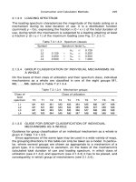
Figure 3.2 Multiple transistor current mirror.
Figure 3.3 NPN current mirror layout. Blue indicates shallow-n+ dop-
ing for emitter and collector ohmic contact. Green indicates shallow-p base.
White indicates contact openings. Light yellow indicates n- epitaxial layer.
mirrorwilldependonthephysicallayoutofthetransistors.Figure3.3
shows two options for “2X” layout.
For current multiplication by an integer value, mirror 2 will be more
accurate. This is because layout and fabrication gradients should affect
the base-emitter junctions of the reference and mirror 2 in a similar
manner. Effects on mirror 1 will be somewhat different. However, for
current multiplication by a fractional value, say 1.5X, mirror 1 can be
laid out to provide the additional current by increasing the emitter area
to be a 1.5X multiple of the reference’s emitter area. Once again, we have
assumed ideal transistors. Let us consider the effect of finite forward
current gain β on the accuracy of our current mirror.
β is defined as I
c
/I
b
. A typical range of values is 100 <β<400. Thus,
for any current to flow in the collector, some current must be flowing
in the base. If our circuit is based on a diode-connected transistor, the
base current will be subtracted from the collector current and an error
willresult.Figure3.4ashowsthecurrentmirrorprovidedwithanideal
Figure 3.4 Multiple transistor current mirror.
reference current I
in
. Since we now have a finite forward current gain,
the currents flowing in the bases of Q1 and Q2 are also supplied by I
in
.
These currents reduce the amount of I
in
that flows in the collector of
Q1. If we approximate the base currents of both Q1 and Q2 as equal,
we have
I
out
= I
c
(Q2) = I
in
− 2
I
c
(Q2)
β
(3.3)
Q1’s base-emitter voltage will reflect the amount of collector current
flowing, and Q2 will mirror a current that is less than I
in
.
Figure3.4bshowsacircuitthatreducestheerrorduetobasecurrent.
Transistor Q3 acts as a buffer and provides the base current for Q1 and
Q2. The emitter current for Q3 is then equal to
I
E
(Q3) = I
b
(Q1) + I
b
(Q2) =
2I
c
(Q1)
β
(3.4)
The base current of Q3 is then given as
I
b
(Q3) =
I
E
(Q3)
β +1
=
2I
c
(Q1)
1+β(β +1)
(3.5)
If we approximate I
in
= I
c
(Q1), we can then say
I
out
I
in
=1−
2
β
2
+ β
(3.6)
The error increases with the number of mirror transistors connected to
the base rail and decreases with increasing current gain.
Example
UsethecircuitsinFigure3.4todeterminethevalueofI
out
if I
in
=
50µA and β = 100. Assume all transistors are identical. Let’s start with
Figure3.4a.Sincethetwotransistorsareidentical,wecanassumethat
whatever collector current exists in Q1 will be mirrored in Q2. Thus,
I
c
(Q1) = I
c
(Q2) = I
c
. Next, we can assume that β is identical, so
base currents will be identical: I
b
(Q1) = I
b
(Q2) = I
b
. Now we can use
Kirchoff’s current law at the collector of Q1 to obtain
I
c
= I
in
−
2I
c
β
(3.7)
This can be rewritten as
I
c
=
I
in
1+
2
β
(3.8)
Thus, I
out
= I
c
=50µA/1.02=49.61µA.
Now,withthecircuitinFigure3.4b,wehavethefollowingrelation-
ships:
I
c
(Q1) = I
c
(Q2) = I
c
= I
out
and
I
b
(Q1) = I
b
(Q2) = I
b
For Q3, we have I
E
(Q3) = 2I
b
and I
b
(Q3) = 2I
b
/(β + 1). Again using
Kirchoff’s current law at the collector of Q1, we obtain
I
in
= I
c
+ I
b
(Q3) = I
c
+
2I
b
β
= I
c
+
2I
c
β
2
+ β
Rewritten, we have
I
c
=
I
in
1+
2
β
2
+β
(3.9)
Thus, I
out
=49.990µA.
We have seen how current gain can be accomplished by using multiples
of emitter area in the mirror transistor. This is a simple extension of
the diode equation. A change in V
be
of 18 mV results in a doubling of
collector current (proof is left as an exercise for the student). Similarly,
changing the emitter area of a transistor can be viewed as directly scaling
the I
s
parameter. If A
E
is scaled by a factor of 2, then I
s
for that
transistor scales by a factor of 2. The same effect can be created using
a resistor.
ConsiderthecircuitinFigure3.5.GivenparticularvaluesofI
in
and
R, the voltage drop developed across R will increase the V
be
of Q2 with
Figure 3.5 Current mirror with output current gain.
the result that I
out
will be greater than I
in
. Every multiple of 18 mV
will result in I
out
being a factor of 2 greater than I
in
. For example, if
R = 360Ω and I
in
=50µA, the voltage drop across R will be 18 mV,
and I
out
will be approximately twice I
in
.
Example
ForthecircuitinFigure3.5,assumeβ=100,I
s
= 200E − 18A,
I
in
= 100µA and the desired value of I
out
is 150µA. Find the required
value of R.
We know the collector current of Q2 will be 150µA. Base current in
Q2 will then be 1.5µA. The collector current in Q1 is then given by
I
c
(Q1)=98.5µA − I
b
(Q1) = 98.5µA −
I
c
(Q1)
β
or
1.01I
c
=98.5µA
This gives I
c
(Q1)=97.525µA. Using Kirchoff’s Voltage Law at the
bases of Q1 and Q2, we find
V
be
(Q2) = V
be
(Q1)+97.525µA R
Now
V
be
(Q1) = V
T
ln
97.5E − 6
200E − 18
=0.6997V
and
V
be
(Q2) = V
T
ln
150E − 6
200E − 18
=0.7109V
Solving the KVL equation, we find
R =
V
be
(Q2) − V
be
(Q1)
97.525µA
= 115Ω
NotethatplacingaresistorintheemitterofQ2asshowninFigure3.6
would serve to decrease the V
be
and would reduce the value of I
out
. The
circuitsinFigures3.5and3.6areexamplesofWidlarcurrentsources.
They are named after Robert Widlar, one of the pioneers in transistor
electronics. Solving for the required resistance from two known currents
is fairly straightforward. It is slightly more difficult to find the output
current from a known input with a fixed value of R.
Figure 3.6 Widlar current mirror.
Example
UsethecircuitinFigure3.6tofindthevalueofI
out
,ifI
in
= 100µA,
β = 100, I
s
= 200E − 18A and R
2
= 100Ω.
Let us start by approximating the base currents. We know the voltage
drop across R will reduce the collector current of Q2. If Q2 carried
100µA, the drop across R would be 10 mV. A change of 18 mV is required
to halve the current, so we can expect current greater than 50µA to be
flowing. Let us approximate I
b
(Q2) as 1µA. Then I
c
(Q1) ≈ 98µA.Now
we can use KVL at the transistor bases:
V
be
(Q1) = V
be
(Q2) + I
out
R
Substituting the diode equation for V
be
, we have
V
T
ln
I
c
(Q1)
I
s
= V
T
ln
I
out
I
s
+ I
out
R
Rearranged, we have
I
out
=
V
T
R
ln
I
C
(Q1)
I
out
This is a transcendental equation. I
out
is both the solution and a variable
within the problem. This requires an iterative solution. Take a first
guess and solve to find a point at which the equation is an identity. The
chart of values below shows the method.
“Guess-timate” Solved value Identity?
50µA 18µA way off
75µA 74.8µA not quite
76µA 71.3µA too far
74.9µA 75.1µA not enough
74.95µA 74.97µA close enough
Fortunately, circuit simulators can perform these operations very quickly.
However, it is good engineering practice to complete a “paper design”
before simulation so that unexpected results can be checked early in the
design phase.
One of the most important qualities of the ideal current source is its
infinite output impedance. The ideal source provides a constant output
current regardless of the voltage of the output node. Practical sources,
however, have finite output resistance that must be considered.
LetusstartwiththemirrorsinFigure3.4.Ineithercircuit,the
output stage is a single transistor. The output resistance of the mirror
is equal to the output resistance of the transistor. We know this quantity
as
r
o
=
V
A
I
c
(3.10)
where V
A
is the Early voltage. The slope with which collector current
increases with increasing collector-emitter voltage is defined as the in-
verse of r
o
. This change in current can be modeled as an extension of
the diode equation:
I
c
= I
s
e
V
be
V
T
1+
V
ce
V
A
(3.11)
Example
ForthecircuitinFigure3.4a,wehavealreadydeterminedthecollector
current to be 49.61 µA. At what value of V
ce
will this be true? What is
I
out
if V
A
= 100V and V
out
=20V ?
Since the reference transistor Q1 has a V
ce
≈ 0.7V , V
ce
(Q2) should be
0.7V for the mirror to work correctly. For V
ce
= V
out
=20V
I
c
(Q2) = I
s
e
V
be
(Q2)
V
T
1+
20
100
I
c
(Q1) = I
s
e
V
be
(Q1)
V
T
1+
0.7
100
So
I
c
(Q2)
I
c
(Q1)
=
1.2
1.07
=1.1215. I
out
has increased by more than 12%. Low-
ering the transistor collector current can increase output resistance, but
this is often not an option in a design. Early voltage is usually fairly well
fixed as a result of the fabrication process. Fortunately, there are several
circuit design options available that allow us to increase r
o
from several
hundreds of kilohms to several megohms. Consider the Widlar current
mirror.AddingtheresistorasshowninFigure3.6helpstoincrease
output resistance. We can understand this more easily by drawing the
small-signalequivalentcircuitasshowninFigure3.7.
Figure 3.7 Widlar current mirror small-signal equivalent circuit.
Since Q1 is diode-connected it is modeled as 1/gm
1
. The quantity r
b
is defined as β/gm. Since r
b
is greater than 1/gm
1
by a factor of β, the
parallel combination of R
1
and 1/gm
1
can be ignored, and the circuit
reducestothatshowninFigure3.8.
Applying test source I
in
, we see that all the test current flows through
the parallel combination of R
2
and r
b2
. The resulting voltage at V
e
is
v
e
= −i
in
(r
b2
R
2
) (3.12)
Figure 3.8 Simplified small-signal equivalent circuit for the Widlar current
mirror.
Current through r
o
is
i(r
o
)=i
in
− gm
2
v
e
= i
in
+ i
in
gm
2
(r
b2
R
2
) (3.13)
Voltage v
in
is then given by the sum of the voltage drops across the two
resistances:
v
in
= −v
e
+ i(r
o
)r
o
(3.14)
Output resistance is then given as
R
o
=
v
in
i
in
= r
b2
R
2
+ r
o
[1 + gm
2
r
b2
R
2
)] (3.15)
Expanding the parallel resistance and reducing the result leads to
R
o
= r
o
1+gm
2
R
2
1+
gm
2
β
Finally, since gm
2
R
2
β, and gm
2
= I
c
(Q2)/V
T
, we obtain
R
o
= r
o
1+
I
c
(Q2)R
2
V
T
(3.16)
This is a very important result because it shows that every increase
of 26 mV across R
2
increases the mirror output resistance by r
o
. That
is, 26 mV across R
2
gives R
o
=2r
o
, 52 mV gives R
o
=3r
o
, etc. This
result can also be extrapolated back to the simple current source. Us-
ing emitter degeneration resistors for both the reference and the mirror
transistors will increase the output resistance, but without introduc-
ing current scaling effects. In general, this technique is limited by the
amount of voltage dropped across resistor R
2
. It is usually not desirable
to have more than about 150 mV across the degeneration resistors.
Another technique to increase the output resistance is called cascod-
ing. A cascode current mirror uses two mirrors stacked one on top of
Figure 3.9 Bipolar cascoded current mirror.
the other and uses the high output resistance of the bottom mirror to
increasetheoutputresistanceofthetopmirrorasshowninFigure3.9.
If we assume that the base voltages do not change with variation of
Q3’s collector voltage, we can use 3.18 with r
o
(Q3) substituted for R
2
:
Ro ≈ r
o
1+gm
2
r
o
(Q3)
1+
gm
2
r
o
(Q3)
β
(3.17)
Thus, R
o
can be increased by a factor of β by cascoding.
It is important to note here that our assumption in this analysis is
flawed. As the collector voltage of Q3 varies, Early voltage effects cause
changes in the collector current. This requires V
be
(Q3) to change slightly
to maintain constant current. A thorough small-signal analysis of the
cascode current source shows an output resistance increase of only β/2.
TheWilsoncurrentmirrorshowninFigure3.10isavariationon
the cascode theme. This circuit uses a negative feedback approach to
maintain a well-regulated output current. Base current cancellation is
also provided, making this circuit relatively insensitive to changes in β.
Base current in Q2 is multiplied by β + 1 and exits Q2’s emitter.
Current flowing in the collector of Q3 causes Q1 to mirror the same
current. If Q2 begins to provide too much current, the mirror action
of Q1 and Q3 decreases the available drive to Q2
s base and limits
the current. If β is constant across all three transistors, base current
cancellation is achieved and a well-regulated output current is provided.
The voltage drop across Q1 is equal to V
be
(Q2) + V
be
(Q3), while Q3
is limited to V
ce
= V
be
. Thus, Early voltage effects can be ignored.
Modulation of Q2
s collector voltage will have very little effect on the
value of output current, which implies a high output resistance. Small
Figure 3.10 Wilson current mirror.
signal analysis yields
R
o
=
βr
o
2
(3.18)
Figure 3.11 A. Vbe/R current reference. B. (delta)Vbe/R current refer-
ence.
TwocommoncurrentreferencesareshowninFigure3.11.TheV
be
/R
currentsourceisshowninFigure3.11a,andthe∆V
be
/R source is shown
inFigure3.11b.
The V
be
/R current source takes its name from its transfer function:
I
out
=
V
be
(Q1)
R
2
=
V
T
R
2
ln
I
c
I
s
(3.19)
The output current is largely independent of supply voltage as long as
sufficient current is available to turn Q1 on. However, large changes in
Q1
s collector current will change its V
be
and can influence the output
current value. The temperature coefficient associated with I
out
will be
negative since V
be
decreases with temperature while integrated resistors
typically increase in value.
The ∆V
be
/R source makes use of the thermal voltage to establish the
output current. The current in Q1 is mirrored to Q2. Q2 has an emitter
area twice that of Q1 with the result that the current density in Q2is
half that of Q1. This results in V
be
(Q2) being lower than V
be
(Q1). The
difference is called ∆V
be
and is dropped across resistor R
1
to set the
output current:
I
out
=
V
T
ln
A
2
A
1
R
(3.20)
In this case, Q1, Q2 and R
1
set up the output currents, but the mirror
output is taken from the PNP transistor current rail.
3.2 Current Mirrors in MOS Technology
MOS devices can be used to build current mirrors in direct analogue
to the bipolar cases. MOS devices operate linearly in the saturation
region. This requires V
gs
>V
th
and V
ds
≥ V
gs
− V
th
. The equation
defining MOS device operation in the saturation region is
I
d
=
W
L
µC
ox
2
(V
gs
− V
th
)
2
)[1 + λ(V
ds
− (V
gs
− V
th
))] (3.21)
Setting µC
ox
= KP and the last instance of V
gs
− V
th
= V
ds
sat
,
Equation 3.21 reduces to
I
d
=
W
L
KP
2
(V
gs
− V
th
)
2
[1 + λ(V
ds
− V
ds
sat
)] (3.22)
Current flows in M1 as a result of V
gs1
.IfM2 is in saturation, and
if W
2
/L
2
= W
1
/L
1
, then I
out
will be equal to I
d1
. In MOS technology,
scaling of currents is easily accomplished by manipulating the W/L ra-
tios of each transistor. However, it is important to keep all the mirror
devices operating in the saturation region to maintain proper operation.
The minimum voltage across the mirror transistor is V
ds
sat
= V
gs
− V
th
.
Figure 3.12 MOS current mirror.
Under these conditions, the output resistance of the current mirror is
the output resistance of the mirror transistor:
R
o
=
1
λI
d
(3.23)
where λ is the channel length modulation parameter.
Five variables are available as design parameters: W
1
, L
1
, W
2
, L
2
and
V
gs
. Normally, values of L and V
gs
are picked first to simplify the design
process. For example, making all values of L equal reduces the current
ratio equation to a ratio of transistor widths:
I
d2
I
d1
=
W
2
W
1
(3.24)
Also, making all values of L the same serves to make the effects of
process variations constant from transistor to transistor. Lateral diffu-
sion, etch effects and photolithography errors will then affect the circuit
in a “common mode” manner. Errors tend to cancel under these con-
ditions. In general, it is a good practice to make L as large as possible
for analog designs. Increasing L reduces the value of λ. Setting L equal
to three times the process minimum length is a good rule to start with.
This rule can be modified after you have experience with a particular
process. It is also a good practice to design for a specific V
gs
that is
somewhat larger than V
th
. Higher values of V
gs
allow smaller values of
W to be used, but the value of V
ds
sat
will be increased. Values of V
gs
that approach V
th
result in physically large transistors.
Example
Design a current mirror using n-channel MOS devices. Use the circuit
showninFigure3.12.AssumesuppliesareV
dd
=5V and ground. Both
reference current and output current are to be 20µA. KP =50µA/V
2
,
L =5µm, V
th
=0.8V and λ =0.04V
−1
. Use V
gs
=1.3V . Determine
the minimum voltage required to stay in saturation and find the output
resistance.
First, we start by calculating the value of R required to provide the
reference current:
R =
V
dd
− V
gs
20µA
=
5V − 1.3V
20E − 6A
= 185kΩ
Since I
out
= I
in
, we can solve for W
1
and W
2
at the same time:
I
d1
= I
d2
=20µA =
W
5E − 6
50E − 6
2
(1.3 − 0.8)
2
From this we obtain W =16µm. The minimum voltage required to
stay in saturation is
V
ds
sat
=1.3 − 8=0.5V
Output resistance is found to be
r
o
=
1
20E − 6 ∗ 0.04
=1.25MΩ
It is important to realize that r
o
of the simple current mirror is pro-
portional to 1/I
d
, and so high output resistance is obtained only for low
values of current.
MOS devices do not use a bias current, and so buffered current mirrors
aren’t needed in MOS technology. However, cascoded sources such as
theoneshowninFigure3.13arefrequentlyused.
An added error term is found in MOS cascode structures. The body
effect results from a non-zero potential between the source and the bulk
semiconductor in which the transistor is built. The body effect results
in an apparent increase in V
th
. For our analysis, we will model the body
effect as a conductance gm
b
that exists in parallel with gm.
Let us also consider V
gs
for a moment. We know that the actual value
of V
gs
must exceed V
th
by some value in order for the transistor to be
in saturation. If we define V
gs
= V
th
+∆V , we can solve the saturation
drain current equation for ∆V :
∆V =
2I
d
L
KPW
(3.25)
Note that V
ds
≥ ∆V to keep the transistor in saturation.
Output current I
out
is determined by the ratio of
W
4
L
2
W
2
L
4
and the value
of I
ref
.IfweassumealltransistorsinFigure3.13areidentical,then
V
gs
(M2) = V
gs
(M4) = V
th
+∆V (3.26)
Figure 3.13 MOS cascoded current mirror.
The voltage at the gates of M1 and M3 is equal to 2∆V
th
+ V
th
.For
M3 to remain in saturation
V
gs
(M3) ≥ 2(V
th
+∆V ) − ∆V − V
th
= V
th
− ∆V (3.27)
The total voltage across the cascoded mirror is then V
th
+2∆V . The
output voltage swing for which the cascoded mirror will remain in sat-
uration has been increased by V
th
− ∆V over the simple mirror.
Small signal output resistance is obtained from the same procedure
used in analysis of the bipolar cascoded mirror. A current I
o
is forced
into the cascode, the voltage V
o
across the source is measured and r
0
is
calculated.TheACequivalentschematicisshowninFigure3.14awith
theequivalentcircuitprovidedinFigure3.14b.
Figure 3.14 A. MOS cascoded current mirror ac-equivalent schematic. B.
Small-signal equivalent circuit for ac-equivalent schematic.
Small signal analysis gives the following equations:
v
4
= i
o
r
o4
(3.28)
v
gs3
= v
bs3
= −v
4
(3.29)
v
o
=(i
o
− gm
3
v
gs3
− gm
b
v
bs3
)r
o3
+ v4 (3.30)
Substituting and rewriting gives
v
o
= i
o
(1 + gm
3
r
o4
+ gm
b3
r
o4
)r
o3
+ i
o
r
o4
(3.31)
Then
r
o
=
V
o
I
o
= r
o3
+ r
o4
+ r
o4
r
o3
(gm
3
+ gm
b3
) (3.32)
Since r
o3
is much less than r
o3
r
o4
(gm
3
+ gm
b3
), this simplifies to
r
o
≈ r
o4
(1 + r
o3
[gm
3
+ gm
b3
] (3.33)
The total output resistance is equal to the output resistance of M4
multiplied by one plus the voltage gain of transistor M3. This result
shows that output resistance can be optimized without requiring any
change to the output current value. Current is set by M 2 and M4,
while output resistance can be increased by dealing with M 3.
Figure 3.15 Improved MOS cascoded current mirror.
One of the biggest drawbacks in using the cascode mirror shown in
Figures3.13and3.14istheincreaseofV
th
+∆V needed to keep M3
and M4 in saturation. An improved cascode current mirror can be built
by inserting a voltage level shifting circuit between the reference and the
output.ThiscircuitisshowninFigure3.15.
ThekeytomakingthecircuitinFigure3.15workcorrectlyisensuring
V
ds
(M1) = V
th
+2∆V .IfV
gs
(M2) = V
th
+∆V , and V
gs
(M1) =
V
th
+2∆V , then the voltage at the gate of M5 is equal to 2Vth+3∆V .
The voltage at the source of M5 is then V
gs
lower, or V
th
+2∆V .
The voltage at the drain of M4 is then only ∆V , and V
gs
(M3) is
V
th
+∆V . Thus, V
ds
(M3) must be greater than or equal to ∆V in order
to maintain saturation and the minimum output voltage is 2∆V .We
have reduced the minimum saturation voltage by V
th
.
Now, how to size the transistors? Analysis of the circuit gives the
following equations:
I
ref
= I
d
(M1) = I
d
(M2) (3.34)
I
d
(M1) =
W
1
L
1
KP
2
(V
gs1
− V
th
)
2
where V
gs1
= V
th
+2∆V (3.35)
I
d
(M2) =
W
2
L
2
KP
2
(V
gs2
− V
th
)
2
where V
gs2
= V
th
+∆V (3.36)
Substituting Equation 3.34 and Equation 3.35 into Equation 3.36 leads
to
W
1
L
1
(2∆V )
2
=
W
2
L
2
∆V
2
(3.37)
This can be written as
W
1
L
1
=
1
4
W
2
L
2
(3.38)
This provides the extra ∆V needed in V
gs
(M1). Setting W
2
/L
2
=
W
4
/L
4
= W
6
/L
6
sets the output current. W
5
/L
5
is set to ensure M5
also operates in saturation while W
3
/L
3
is set to optimize output resis-
tance.
3.3 Chapter Exercises
1.UsingthesimplecurrentmirrorinFigure3.1,designacircuitthat
has a reference current of 150 µA. Transistor saturation current,
I
s
=2E − 16. Assume β = 100, β = 400, β = ∞. Find V
be
to 1%
accuracy. What is the percentage error in output current for the
three cases above?
2. If the circuit described in problem 1 with β = 250, what is the
output current variation if there were ±5% variation in the value
of the supply voltage?
3. For the circuit described in problem 1 with β = 250, what is
the output current variation if the manufacturing tolerance on the
value of R is ±30%?
4. For the circuit in problem 1 with β = 250, what is the variation in
output current if resistor R has a temperature coefficient (abbre-
viated as TC) of + 2500 parts per million (abbreviated as PPM)
per degree Centigrade over the temperature range from 0 deg C
to 70 deg C, where 25 deg C is typical? You should include the
temperature variation of −2mV/ deg C for V
be
as well.
5. Problems 1 through 4 have completed a sensitivity analysis for the
base design. Comment on the expected total error and the maxi-
mum possible error for this design. What should the specification
be for this design over supply voltage, temperature and manufac-
turing tolerance? What is the major cause of the error? How can
this problem be designed out?
6. Prove that a change in V
be
of 18 mV results in a doubling in the
value of I
c
.
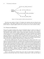
Figure 3.16 Schematic for exercise 7.
7.UsetheschematicshowninFigure3.16.Expandthediodeequa-
tion to obtain an equation that accounts for differences in emitter
areas A
1
and A
2
and for resistors R
1
and R
2
. Assume ideal tran-
sistors.
8.UsetheschematicinFigure3.6todesignaWidlarcurrentmirror.
I
ref
=75µA and R = 100Ω. What is I
out
? What value of R is
required for I
out
=20µA?
9. What is the output resistance of the circuit described in problem
1 if the Early voltage is 100V?
10. What is the output resistance of the Widlar mirror designed in
exercise 1.8 if V
A
= 100V ?
11. Complete the small-signal analysis for the Wilson mirror and prove
the validity of equation 3.18.
12. Design a V
be
/R current source with I
out
=25µA. If the tem-
perature coefficient of V
be
is −2mV/ deg C and the temperature
coefficient of resistance is +2500 ppm, what is the tolerance on
I
out
from −25 deg C to +75 deg C?
13. Design a ∆V
be
/R current source with I
out
=25µA. If the tem-
perature coefficient of V
be
is −2mV/ deg C and the temperature
coefficient of resistance is +2500 ppm, what is the tolerance on
I
out
from −25 deg C to +75 deg C?
14. Design a current mirror using n-channel MOS devices. Use the
circuitshowninFigure3.12.AssumesuppliesareV
DD
=5V
and ground. Reference current is 20µA. Output currents are to
be 20µA,40µA,55µA, and 70µA. KP =50µA/V
2
, L =5µm,
V
th
=0.8V and Λ = 0.04V
−1
. Determine the minimum voltage
required to stay in saturation and then find the output resistance
for each output.
15.DesignacascodedNMOSmirrorusingFigure3.13asatemplate.
Use a reference current of 10µA. Provide an output current of
50µA with an output resistance of 25MΩ. Use KP, V
th
and Λ
from exercise 14.
16. Redesign the cascoded mirror from exercise 15 to improve the out-
putvoltageswing.UsethecircuitinFigure3.15asatemplate,
and use the MOS device parameters from exercise 14.
References
[1] Baker, R. Jacob, et al, CMOS Circuit Design, Layout and Simu-
lation, IEEE Press, New York, c. 1998.
[2] Gray, Paul R., and Mayer, Robert G., Analysis and Design of
Analog Integrated Circuits, 2nd edition, John Wiley and Sons, Inc.,
New York, c. 1984.
[3] Millman, Jacob, and Grabel, Arvin, Microelectronics, 2nd edition,
McGraw-Hill Book Company, New York, c. 1987.
chapter 4
Voltage References
4.1 Simple Voltage References
An ideal voltage reference produces a voltage that is constant and does
not change with factors such as current loading, power supply varia-
tions, or temperature. Such references are useful in applications where
a given voltage is compared to a standard such as in analog to digital
converters and also for the generation of regulated supply voltages for
digital circuits from a higher voltage analog supply.
A common way to provide a voltage is to use the voltage divider con-
sisting of two resistors in series. The output voltage is V
o
=
R
1
R
1
+R
2
V
CC
.
The voltage divider has the advantage of simplicity, but the output is
sensitive to power supply variations and to changes in current drawn
from the V
o
terminal.
The sensitivity of the output voltage to power supply variations is
defined as
S
V
O
V
CC
=
dV
o
V
o
dV
CC
V
CC
=
V
CC
V
o
dV
o
dV
CC
The fraction
dV
o
V
o
can be expressed in units of percent change or in parts
per million(ppm). For the voltage divider, the sensitivity to the power
supply voltage is
S
V
O
V
CC
=1
This means the percent change in the output voltage equals the percent
change in V
CC
.
The sensitivity to load current is
S
V
O
I
o
=
I
o
V
o
dV
o
dI
o
Since the output depends on the ratio of R
2
to R
1
, it will be to a first
order, independent of variations in resistance values. An accurate value
for V
o
depends on the ability to match resistance values.
Figure 4.1 A. Buffered divider. B. Temperature compensated buffered
divider.
ConsiderthecircuitshowninFigure4.1A.Thebuffereddividershown
uses a resistor divider to create a reference voltage. The NPN transistor
provides relatively high levels of output current with minimal loading on
the resistor divider node. The V
be
of the transistor does lower the output
reference voltage by about 0.7V , and changing current levels will result
in some change in the output voltage as the V
be
changes. Additionally,
supply voltage variation and temperature changes will affect the output
voltage. But other than that, it’s a great little circuit! We can get some
temperature compensation by adding a second NPN to the circuit as
showninFigure4.1B,buttheothersensitivitiesarestillthere.
Since the buffered divider output is down one V
be
from the divider
reference voltage, temperature variations will cause the output to vary
at approximately 2mV/ deg C. The sensitivity to V
cc
is unity, the same
as the voltage divider.
4.2 Vbe Multiplier
The effects of supply variation can be minimized by “decoupling” the
output from V
cc
.ConsiderthecircuitshowninFigure4.2A.Thebase
of transistor N
1
is at 3V
be
. The output V
o
is 2V
be
≈ 1.4V . The output
voltage is, to a first order, independent of V
cc
. The output transistor N
1
can provide reasonable current, and changes in supply voltage affect the
output voltage only insofar as the current through the diodes changes the
diode V
be
values. Doubling the value of V
cc
will only raise the reference
by about 54mV . However, this circuit has its problems. It has a large
negative temperature coefficient due to the multiple V
be
s in the reference
diode string. Only multiples of V
be
are possible as output reference
voltage. Finally, the use of many diodes can consume large die areas,
causing designs to grow and leading to higher manufacturing costs. Once
again,wecanaddresstheshortcomingsofthiscircuit.Figure4.2Bshows
a circuit where we have used only two transistors, but note how the use
of resistors R
1
and R
2
now allow the use of any multiple of V
be
to be
used.
Figure 4.2 Vbe multiplier voltage references. V
o
is a multiple of V
be
.
A. Diode dependent voltage reference. B. V
be
multiplier voltage reference.
The configuration of these resistors and the transistor N
1
form a cir-
cuit known as a V
be
multiplier. Neglecting base current to transistor N
1
,
the base-emitter voltage of N
1
is
R
1
R
1
+R
2
V
A
, where V
B
is the voltage at
the base of N
2
. The output voltage V
o
is one V
be
below V
B
:
V
o
=
R
1
+ R
2
R
1
V
be
− V
be
=
R
1
R
2
V
be
The current through R
3
has three components. R
3
provides current for
the voltage divider R
1
R
2
. It provides base current for N
2
. The third
component of current through R
3
is N
1
collector current. N
1
adjusts its
collector current to assure V
B
, the N
2
base voltage is correct provided
R
3
is small enough to furnish sufficient current. The circuit will go
out of regulation when the load current increases to a point where the
base current to N
2
steals the current from the voltage divider that is
required to maintain one V
be
across R
1
. N
1
acts as a feedback amplifier
to stabilize the voltage at node B. As more current is drawn from the
output, the voltage at node B, the base of N
1
drops. This causes the
voltage across R
1
to drop. With its V
be
decreasing, N
1
begins to turn