ccnp 642 811 bcmsn exam certification guide second edition phần 3 docx
Bạn đang xem bản rút gọn của tài liệu. Xem và tải ngay bản đầy đủ của tài liệu tại đây (2.33 MB, 63 trang )
Switch File Management 93
Filename Conventions
IOS image files are named according to a predefined format. The filenames follow this basic
template:
mmmmm-fffff-mm.vvvv.bin
■ mmmmm represents the Catalyst switch model (for example, c3550 corresponds to Catalyst
3550, cat4000 to Catalyst 4000, and c6sup22 to Catalyst 6500 Supervisor II).
■ fffff represents the feature sets included in the image; generally, i followed by anything denotes
an IP feature set, s is the IP “Plus,” k denotes a cryptographic feature set (Data Encryption
Standard [DES] or 3DES), j is the enterprise set, p is for service providers, and d is the desktop
(IP, IPX, AppleTalk, DECnet) feature set.
■ mm denotes the file format: The first letter is m if the image runs in RAM, and the second letter
is z if the image is Zip compressed.
■ vvvv represents the IOS version, in the format vvv-mmm.bbb; the major release (vvv) is given
first and followed by a dash; then, the maintenance release (mmm) is given and followed by a
period. The build level (bbb) is given using one or more letters and a number. The first letter
denotes the type of build: E means an early deployment of features. The next letter is the interim
build level, where A means the first build, and so on. The number following denotes the number
of times the interim build has been incrementally released.
Therefore, 121-12c.EA1 means version 12.1(12c)EA1, or early deployment build A1 (the first
“A” build) of the 12.1(12c) code.
■ .bin flags the image file as a binary executable (not readable text).
Configuration Files
The switch configuration is a file containing all the commands needed to configure each switch
feature and function. Here are three of the most common configuration files:
■ startup-config—When a switch first boots up, the startup-config file is read, parsed, and
executed. The startup-config is stored in NVRAM (actually the nvram: file system) so it
survives power failures.
■ running-config—While a switch is running, this contains a copy of the current state of every
command in use. This file is dynamic, such that it is updated with each configuration command
entered.
The running-config’s contents are volatile, causing all commands in it to be lost during a power
failure or a switch reload. (To preserve the running-config, it must be copied into the startup-
config prior to the next switch reload.)
1-58720-077-5.book Page 93 Tuesday, August 19, 2003 3:16 PM
94 Chapter 4: Switch Configuration
■ vlan.dat—As VLANs are defined or changed, their configurations are entered into the VLAN
database file, vlan.dat. This file is updated as you make configuration changes to the VLAN database
on a switch and as any VLAN Trunking Protocol (VTP) updates occur.
The VLAN database (vlan.dat) is stored in Flash memory and is normally configured through
the vlan database or vlan configuration commands. Its contents are preserved across a power
failure or reload.
Other Catalyst Switch Files
You can also find several other files stored in the file systems on a Catalyst switch. Most of the time,
you will not need to do anything with them. They are mentioned here for your understanding and if
you need to access the information they contain. These files can include the following:
■ system_env_vars—A text file containing system variables such as the MAC address, model
number, serial number, and various module information. This file is consulted to get the system
information displayed by the show version command.
■ crashinfo—A file or directory containing text output from previous switch crashes. This is
normally stored and accessed as flash:crashinfo (a file) or crashinfo: (a directory).
Moving Catalyst Switch Files Around
A switch can copy files to and from various locations, including those in Table 4-2.
Table 4-2 Locations of Catalyst Switch Files
File System Name Function
flash:
Flash memory, usually containing bootable IOS image files (some models
emulate nvram: here)
bootflash:
Flash memory, usually containing bootable IOS image files
slot0:
Optional removable Flash card memory; can store any type of files
nvram:
NVRAM area, usually containing the startup-config file
system:
RAM area; contains the running-config file, as well as a directory of all dynamic
switch memory areas
tftp:
An external TFTP server where any type of switch file can be stored or retrieved;
no user authentication needed
ftp:
An external FTP server where any type of switch file can be stored or retrieved;
user authentication required
rcp:
An external rcp server where any type of switch file can be stored or retrieved;
user authentication required
1-58720-077-5.book Page 94 Tuesday, August 19, 2003 3:16 PM
Switch File Management 95
Cisco IOS Software allows you to navigate and manipulate the Flash file system in much the same
way other operating systems, such as UNIX and DOS, do. In Flash memory, you can find plain text
files, binary executable files, and directories. You are free to “move” up and down into directories.
You can also copy, rename, or delete files.
In the EXEC mode, you are always positioned in the “root” directory, flash:, by default. To perform
a function in the Flash file system, use one of the following commands:
■ dir [flash:[directory]]—Show a list of all files in the current Flash directory or the directory
given.
■ cd flash:directory—Change directory to the directory given.
■ cd —Change directory one level up.
■ cd—Change directory to the home or root Flash directory.
■ copy flash:[filename] tftp:—Copy the file filename from Flash to a TFTP server. The server
address and destination filename are prompted.
■ copy tftp: flash:[filename]—Copy a file from the TFTP server into Flash memory. The TFTP
server address and any unresolved filenames are prompted.
■ delete flash:filename—The file filename is deleted from Flash memory.
■ erase flash:—All files in Flash memory are erased in one command.
■ format flash:—The Flash file system is reformatted, destroying all existing files. Formatting is
appropriate when the Flash memory has been corrupted.
You can also manipulate the switch configuration files from privileged EXEC (enable) mode.
Remember that two configuration files exist at all times—the running-config and startup-config.
Any configuration changes you make to a switch are applied immediately to the running-config file.
The only way to update the startup-config is by manually copying another file to it.
Cisco IOS Software allows the following commands to manipulate the configuration files:
■ copy running-config startup-config—The contents of the running-config are copied into
the startup-config, replacing any similar commands there. After this is done, any dynamic
configuration changes are saved and are preserved across power failures or switch reloads.
(This command should be used regularly to save any new configuration changes. Use it
prudently, if you need to back out a large number of changes.)
■ copy startup-config running-config—The permanent contents of the startup-config file are
copied into the running-config, replacing any similar commands there. The entire running-
config isn’t simply overwritten; rather, the startup-config commands are copied over while any
other existing running-config commands are kept active. This operation is performed as a
switch boots up. (This command can quickly restore a misconfigured switch to a known state.)
1-58720-077-5.book Page 95 Tuesday, August 19, 2003 3:16 PM
96 Chapter 4: Switch Configuration
■ copy running-config tftp:—A switch’s current running configuration is copied to a TFTP
server. The server address and destination filename are prompted. Use this command to store a
backup snapshot copy of the switch configuration.
■ copy tftp: startup-config—When a switch configuration is lost or needs to be restored to a known
state, a backup copy of the configuration is copied from a TFTP server to the startup-config file.
The new changes won’t take effect until the switch is reloaded, or until the startup-config is
copied to the running-config. (You could also use copy tftp: running-config, but this would
make immediate configuration changes as commands from the TFTP file are copied over. Use
caution so that your configuration changes occur under controlled circumstances.)
■ erase startup-config—The entire contents of the startup-config file are erased. Use this
command when a switch has been retired from one function and needs to be relocated or
completely reconfigured.
Troubleshooting from the Operating System
The Cisco Catalyst IOS Software provides many commands that can verify or troubleshoot a switch
in its current environment. Sometimes, you might wonder what software image or configuration
commands are being used by a switch. A switch can also produce real-time debugging information
about a feature or condition to aid in troubleshooting. Information is also available to help identify
other neighboring Cisco devices in a network. This section explains each of these tasks and how to
accomplish them using the relevant commands.
Show Configuration and File Contents
Cisco IOS Software offers many commands that you can use from the EXEC mode command line
to display the contents of files, current configuration states, and values for troubleshooting. You can
use the following commands to view and troubleshoot switch files and file systems:
■ show version—Displays the current version of IOS running in a switch, along with many
details about available hardware, RAM and Flash memory, switch uptime, current running IOS
image file, reason for the last reload, and the configuration register’s contents.
■ show running-config [interface type mod/num | vlan vlan-id | module mod]—Displays the
contents of the running-config configuration file. You can jump to the relevant configuration of
a specific interface, VLAN, or switch module, if desired.
■ show startup-config—Displays the startup-config configuration file’s contents.
■ show tech-support—Provides information to Cisco TAC support personnel; almost every
known bit of information about the switch is displayed. Be sure to configure your terminal
emulator to capture text to a file before issuing this command.
1-58720-077-5.book Page 96 Tuesday, August 19, 2003 3:16 PM
Troubleshooting from the Operating System 97
■ verify flash:filename—Verifies the checksum of the Flash file filename. This can ensure that an
IOS image is not corrupted after it has been copied into Flash memory. (During the actual copy
process, the checksum is automatically verified. You can use the verify command to make sure
the file has not become corrupted since it was originally copied.)
■ more filesystem:filename—Displays the contents of a plain text file from the command line.
This can be useful when you need to read configuration files that have been stored in a Flash
file system. You can also view text files that are stored on a remote TFTP server—from the IOS
command line.
Debugging Output
For more focused and real-time information about a certain switch feature, you can use the debug
EXEC command. Debug output is not normally used, unless you suspect a problem with a feature
or an interaction with other switches in the network.
You can use many options with the debug command—each pertaining to a switch feature or a
specific activity. Type the debug command followed by ? to get context-based help on all the
supported debugging commands and keywords.
After you enable a debug command, you can see the debug output listed as events can occur on the
switch.
NOTE You can filter the output of any show command so that you see only lines containing
specific keywords. Append the “pipe” symbol (|) to the command line, followed by one of these
keywords: begin text (start the output with the line containing text), include text (only display
lines that contain text), or exclude text (only display lines that don’t contain text).
When a large amount of output is displayed, the switch usually shows a page at a time, pausing
with a “-More-” prompt. You can either press the SPACE key to display the next page, the
RETURN (Enter) key to display the next line, or /text to search forward and begin the page of
output at the line containing text. Using the slash key allows a quick search within the context of
the entire output.
CAUTION Use the debug commands cautiously because they can generate a tremendous amount
of output. Not only can this display slowly on a serial console connection, but also the debug
process itself can bog the switch CPU down to the point that it severely impacts traffic forwarding.
1-58720-077-5.book Page 97 Tuesday, August 19, 2003 3:16 PM
98 Chapter 4: Switch Configuration
Always be sure to turn off any debugging commands when you finish with them. Do so by using the
no debug options command, where the options keywords match the ones you used to enable
debugging. To quickly disable all active debugging commands, use the no debug all or undebug
all commands.
View CDP Information
To view information learned from CDP advertisements of neighboring Cisco devices, use one of the
following commands:
Switch# ss
ss
hh
hh
oo
oo
ww
ww
cc
cc
dd
dd
pp
pp
ii
ii
nn
nn
tt
tt
ee
ee
rr
rr
ff
ff
aa
aa
cc
cc
ee
ee
[
type
mod
/
num
]
Switch# ss
ss
hh
hh
oo
oo
ww
ww
cc
cc
dd
dd
pp
pp
nn
nn
ee
ee
ii
ii
gg
gg
hh
hh
bb
bb
oo
oo
rr
rr
ss
ss
[
type
mod/num
| vv
vv
ll
ll
aa
aa
nn
nn
vlan-id
] [dd
dd
ee
ee
tt
tt
aa
aa
ii
ii
ll
ll
]
The first command displays CDP information pertaining to a specific interface. If the type, module,
and port information is omitted, CDP information from all interfaces is listed. The second command
displays CDP information about neighboring Cisco devices. A specific interface or VLAN can be
given to display only neighbors connected to it. Using the detail keyword results in the display of
all possible CDP information about each neighbor.
Recall that CDP messages are sent out every 60 seconds, and all entries received are placed in a
cache. The cache is updated with new entries, and stale entries are aged out after a hold time of 180
seconds. If you suspect a problem with a neighboring switch, you might want to clear the CDP cache
of all potentially state information to see what new information is being received from neighbors.
Do this with the clear cdp table command.
As demonstrated in Example 4-1, the show cdp neighbors and the show cdp neighbors detail
command can be useful when you are connected to a switch and need to know more about what
other switches are nearby in a network. Particularly useful are the IP address entries, allowing Telnet
access to previously unknown switches. To see a brief listing of only the neighbor switch names and
their management IP addresses, use the show cdp entry * protocol command.
Example 4-1 Displaying CDP Information for Neighboring Devices
Switch# ss
ss
hh
hh
oo
oo
ww
ww
cc
cc
dd
dd
pp
pp
nn
nn
ee
ee
ii
ii
gg
gg
hh
hh
bb
bb
oo
oo
rr
rr
ss
ss
Capability Codes: R - Router, T - Trans Bridge, B - Source Route Bridge
S - Switch, H - Host, I - IGMP, r - Repeater
Device ID Local Intrfce Holdtme Capability Platform Port ID
BuildingA-1 Gig 2/1 158 S I WS-C3550-4Gig 0/1
CoreSwitch-1 Gig 1/1 158 T S WS-C6509 4/16
Switch# ss
ss
hh
hh
oo
oo
ww
ww
cc
cc
dd
dd
pp
pp
nn
nn
ee
ee
ii
ii
gg
gg
hh
hh
bb
bb
oo
oo
rr
rr
ss
ss
gg
gg
ii
ii
gg
gg
11
11
//
//
11
11
dd
dd
ee
ee
tt
tt
aa
aa
ii
ii
ll
ll
Device ID: CoreSwitch-1
Entry address(es):
IP address: 192.168.199.9
1-58720-077-5.book Page 98 Tuesday, August 19, 2003 3:16 PM
Troubleshooting from the Operating System 99
Platform: WS-C6509, Capabilities: Trans-Bridge Switch
Interface: GigabitEthernet1/1, Port ID (outgoing port): 4/16
Holdtime : 130 sec
Version :
WS-C6509 Software, Version McpSW: 7.2(2) NmpSW: 7.2(2)
Copyright (c) 1995-2002 by Cisco Systems
advertisement version: 2
VTP Management Domain: 'Core'
Switch# ss
ss
hh
hh
oo
oo
ww
ww
cc
cc
dd
dd
pp
pp
ee
ee
nn
nn
tt
tt
rr
rr
yy
yy
**
**
pp
pp
rr
rr
oo
oo
tt
tt
oo
oo
cc
cc
oo
oo
ll
ll
Protocol information for BuildingA-1 :
IP address: 192.168.199.107
Protocol information for CoreSwitch-1 :
IP address: 192.168.199.9
Switch#
Example 4-1 Displaying CDP Information for Neighboring Devices (Continued)
1-58720-077-5.book Page 99 Tuesday, August 19, 2003 3:16 PM
100 Chapter 4: Switch Configuration
Foundation Summary
The Foundation Summary is a collection of tables that provides a convenient review of many key
concepts in this chapter. If you are already comfortable with the topics in this chapter, this summary
can help you recall a few details. If you just read this chapter, this review should help solidify some
key facts. If you are doing your final preparation before the exam, the following tables are a
convenient way to review the day before the exam.
Table 4-3 Switch Management Configuration Commands
Task Command Syntax
Identify switch hostname hostname
Set EXEC level password line type number
password password
Set privileged level password enable secret password
Set IP address interface vlan vlan-id
ip address ip-address netmask
ip default-gateway ip-address
CDP (default is enabled on every switch port) cdp enable
Table 4-4 File Management Commands
Task Command Syntax
Directory of Flash dir [flash:[directory]]
Change directory cd flash:directory
Copy a file between Flash and a TFTP server copy flash:[filename] tftp:
-OR-
copy tftp: flash:[filename]
Delete a file in Flash delete flash:filename
1-58720-077-5.book Page 100 Tuesday, August 19, 2003 3:16 PM
Foundation Summary 101
Clear Flash contents erase flash:
-OR-
format flash:
Save the running configuration copy running-config startup-config
-OR-
copy running-config tftp:
Overwrite the running configuration copy startup-config running-config
Overwrite the permanent configuration copy tftp: startup-config
-OR-
erase startup-config
Table 4-5 Troubleshooting Commands
Task Command Syntax
Display the current running environment and
IOS version
show version
Display the running configuration show running-config [interface type mod/num | vlan
vlan-id | module mod]
Display the permanent configuration show startup-config
-OR-
show config
Display all technical support information show tech-support
Verify an image checksum verify flash:filename
continues
Table 4-4 File Management Commands (Continued)
Task Command Syntax
1-58720-077-5.book Page 101 Tuesday, August 19, 2003 3:16 PM
102 Chapter 4: Switch Configuration
Enable or disable debugging debug keywords
no debug keywords
-OR-
no debug all
-OR-
undebug all
Display CDP information show cdp interface [type mod/num]
-OR-
show cdp neighbors [type mod/num | vlan vlan-id]
[detail]
-OR-
show cdp entry * protocol
Table 4-5 Troubleshooting Commands (Continued)
Task Command Syntax
1-58720-077-5.book Page 102 Tuesday, August 19, 2003 3:16 PM
Q&A 103
Q&A
The questions and scenarios in this book are more difficult than what you should experience on the
actual exam. The questions do not attempt to cover more breadth or depth than the exam; however,
they are designed to make sure that you know the answer. Rather than allowing you to derive the
answer from clues hidden inside the questions themselves, the questions challenge your
understanding and recall of the subject. Hopefully, these questions will help limit the number of
exam questions on which you narrow your choices to two options and then guess.
You can find the answers to these questions in Appendix A.
1. When Cisco IOS Software is used on a Catalyst switch, the switch must perform routing. True
or false?
2. What is the major difference between the IOS and CatOS command sets?
3. What switch command will enter privileged EXEC or “enable” mode on a Catalyst 4500?
4. Match these default command line prompts with their respective modes:
a. Switch# Normal user EXEC mode
b. Switch(config) Privileged EXEC or enable
c. Switch(config-if)# Global configuration
d. Switch> Interface configuration
5. With the command line prompt testlab#, what command has been used to customize the
prompt?
1-58720-077-5.book Page 103 Tuesday, August 19, 2003 3:16 PM
104 Chapter 4: Switch Configuration
6.
The following commands have just been entered, assuming interface VLAN 10 did not
previously exist:
ii
ii
nn
nn
tt
tt
ee
ee
rr
rr
ff
ff
aa
aa
cc
cc
ee
ee
vv
vv
ll
ll
aa
aa
nn
nn
11
11
00
00
ii
ii
pp
pp
aa
aa
dd
dd
dd
dd
rr
rr
ee
ee
ss
ss
ss
ss
11
11
99
99
22
22
11
11
66
66
88
88
11
11
99
99
99
99
11
11
00
00
22
22
55
55
55
55
22
22
55
55
55
55
22
22
55
55
55
55
00
00
nn
nn
oo
oo
ss
ss
hh
hh
uu
uu
tt
tt
dd
dd
oo
oo
ww
ww
nn
nn
Suddenly, the power cord is pulled out of the switch. What will happen when the power is
restored?
7. Can you configure an enable secret password (enable secret password) for the switch console
and a different enable secret for Telnet access?
8. When you configure an IP address and subnet mask on a Layer 2 switch for management
purposes, which VLAN are you required to use?
a. VLAN 1
b. VLAN 0
c. VLAN 1001
d. Any VLAN that is appropriate
e. You can’t assign an IP address to a VLAN.
9. What commands will allow Telnet and ping access to a switch management interface at
192.168.200.10, subnet mask 255.255.255.0, on VLAN 5? A router is available at address
192.168.200.1.
10. CDP advertisements occur every seconds.
11. When a Cisco Catalyst switch receives a CDP multicast frame, it relays it to neighboring
switches. True or false?
12. Eight access layer switches connect to a central distribution layer switch using Gigabit Ethernet
connections. Each connection is assigned to VLAN 1 so that no link is in trunking mode. On
one of the access switches, how many neighboring switches will be shown by the show cdp
neighbor gigabit 0/1?
13. Which IOS image file is more recent: c3550-i5q3l2-mz.121-12c.EA1.bin or
c3550-i9q3l2-mz.121-11c.EA1.bin?
14. A new switch has just been configured with 100 command lines from the console. You realize
the need to save the new configuration and type copy start run. Where will your configuration
be stored?
15. What command can you use to see what Cisco IOS Software version is currently running on a
switch?
1-58720-077-5.book Page 104 Tuesday, August 19, 2003 3:16 PM
Q&A 105
16.
Complete this command so that the output is displayed starting with the configuration for
interface VLAN 100:
show run
17. The debug spanning-tree all command has been given from the EXEC mode command line.
What commands can you use to stop or disable the debugging output?
18. What command can you use to verify CDP configuration on switch port GigabitEthernet 3/1?
1-58720-077-5.book Page 105 Tuesday, August 19, 2003 3:16 PM
This chapter covers the
following topics that you
need to master for the CCNP
BCMSN exam:
■ Ethernet Concepts—This section discusses
the concepts and technology behind various
forms of Ethernet media. Ethernet solutions
for service providers, such as Long Reach
Ethernet (LRE) and Metro Ethernet, are also
covered.
■ Connectivity with Scalable Ethernet—This
section covers the configuration steps and
commands needed to use Catalyst Ethernet,
Fast Ethernet, and Gigabit and 10Gigabit
Ethernet switch ports in a network.
■ Connecting Switch Block Devices—This
section discusses the physical cabling and
connectivity used with Catalyst switches,
including console and Ethernet interfaces.
■ Troubleshooting Port Connectivity—This
section covers some of the symptoms,
methods, and switch commands that you can
use to diagnose problems with Ethernet
switch connections.
1-58720-077-5.book Page 106 Tuesday, August 19, 2003 3:16 PM
C H A P T E R
5
Switch Port Configuration
Chapters 1 and 2 dealt with the logical processes that you can use to design a campus network.
Connections between switch blocks were discussed, such that traffic could be efficiently trans-
ported across the campus. Single connections, load balancing, and redundant paths connected
switches in modular blocks for complete connectivity. However, these paths were only functional
paths—no specifics were presented about how much traffic the network could handle, or what
physical capabilities were supported. These topics become important when you begin to size
traffic loads and actually connect Cisco switch devices.
This chapter presents the various Ethernet network technologies used to establish switched
connections within the campus network. The chapter also details the switch commands required
for configuring and troubleshooting Ethernet LAN ports.
”Do I Know This Already?” Quiz
The purpose of the “Do I Know This Already?” quiz is to help you decide if you need to read
the entire chapter. If you already intend to read the entire chapter, you do not necessarily need
to answer these questions now.
The 13-question quiz, derived from the major sections in the “Foundation Topics” portion of the
chapter, helps you determine how to spend your limited study time.
Table 5-1 outlines the major topics discussed in this chapter and the “Do I Know This Already?”
quiz questions that correspond to those topics.
1-58720-077-5.book Page 107 Tuesday, August 19, 2003 3:16 PM
108 Chapter 5: Switch Port Configuration
1.
What does the IEEE 802.3 standard define?
a. Spanning Tree Protocol
b. Token Ring
c. Ethernet
d. Switched Ethernet
2. At what layer are traditional 10 Mbps Ethernet, Fast Ethernet, and Gigabit Ethernet the same?
a. Layer 1
b. Layer 2
c. Layer 3
d. Layer 4
3. At what layer are traditional 10 Mbps Ethernet, Fast Ethernet, and Gigabit Ethernet different?
a. Layer 1
b. Layer 2
c. Layer 3
d. Layer 4
Table 5-1 “Do I Know This Already?” Foundation Topics Section-to-Question Mapping
Foundation Topics Section Questions Covered in This Section
Ethernet Concepts 1-8
Connecting Switch Block Devices 9-10
Switch Port Configuration 11
Troubleshooting Port Connectivity 12-13
CAUTION The goal of self-assessment is to gauge your mastery of the topics in this chapter. If
you do not know the answer to a question or are only partially sure of the answer, you should mark
this question wrong. Giving yourself credit for an answer you correctly guess skews your self-
assessment results and might provide you with a false sense of security.
1-58720-077-5.book Page 108 Tuesday, August 19, 2003 3:16 PM
”Do I Know This Already?” Quiz 109
4.
What is the maximum cable distance for a Category 5 100BASE-TX connection?
a. 100 feet
b. 100 meters
c. 328 meters
d. 500 meters
5. Where is Cisco Long Reach Ethernet typically used?
a. In a campus access layer (to the desktop users)
b. In a campus core layer
c. Between campus buildings
d. In a multitenant building
6. What is the maximum length of a Cisco LRE connection?
a. 100 feet
b. 100 meters
c. 500 feet
d. 5000 feet
7. Ethernet autonegotiation determines which of the following?
a. Spanning Tree mode
b. Duplex mode
c. Quality of service mode
d. Error threshold
8. Which of the following cannot be determined if the far end of a connection doesn’t support
autonegotiation?
a. Link speed
b. Link duplex mode
c. Link media type
d. MAC address
1-58720-077-5.book Page 109 Tuesday, August 19, 2003 3:16 PM
110 Chapter 5: Switch Port Configuration
9.
Which of these is not a standard type of Gigabit Interface Converter (GBIC)?
a. 1000BASE-LX/LH
b. 1000BASE-T
c. 1000BASE-FX
d. 1000BASE-ZX
10. What type of cable should you use to connect two switches back-to-back using their
FastEthernet 10/100 ports?
a. Rollover cable
b. Transfer cable
c. Crossover cable
d. Straight-through cable
11. Assume you have just entered the configure terminal command. To configure the speed of the
first FastEthernet interface on a Catalyst 3550 to 100 Mbps, which of these commands should
you enter first?
a. speed 100 mbps
b. speed 100
c. interface fastethernet 0/1
d. interface fast ethernet 0/1
12. If a switch port is in the “errdisable” state, what is the first thing you should do?
a. Reload the switch.
b. Use the clear errdisable port command.
c. Use the shut and no shut interface configuration commands.
d. Determine the cause of the problem.
13. Which of the following show interface outputs can you use to diagnose a switch port problem?
a. Port state
b. Port speed
c. Input errors
d. Collisions
e. All of the above
1-58720-077-5.book Page 110 Tuesday, August 19, 2003 3:16 PM
”Do I Know This Already?” Quiz 111
You can find the answers to the quiz in Appendix A, “Answers to Chapter ‘Do I Know This
Already?’ Quizzes and Q&A Sections.” The suggested choices for your next step are as follows:
■ 7 or less overall score—Read the entire chapter. This includes the “Foundation Topics,”
“Foundation Summary,” and “Q&A” sections.
■ 8–10 overall score—Begin with the “Foundation Summary” section and follow up with the
“Q&A” section at the end of the chapter.
■ 11 or more overall score—If you want more review on these topics, skip to the “Foundation
Summary” section and then go to the “Q&A” section at the end of the chapter. Otherwise, move
to the Chapter 6, “VLANs and Trunks.”
1-58720-077-5.book Page 111 Tuesday, August 19, 2003 3:16 PM
112 Chapter 5: Switch Port Configuration
Foundation Topics
Ethernet Concepts
This section reviews the varieties of Ethernet and their application in a campus network. Recall how
the bandwidth requirements for each network segment are determined by the types of applications
in use, the traffic flows within the network, and the size of the user community served. Ethernet
scales to support increasing bandwidths and should be chosen to match the need at each point in the
campus network. As network bandwidth requirements grow, you can scale the links between access,
distribution, and core layers to match the load.
Other network media technologies available include Fiber Distribution Data Interface (FDDI),
Copper Distribution Data Interface (CDDI), Token Ring, and Asynchronous Transfer Mode (ATM).
Although some networks still use these media, Ethernet has emerged as the most popular choice in
installed networks. Ethernet is chosen because of its low cost, market availability, and scalability to
higher bandwidths.
Ethernet (10 Mbps)
Ethernet is a LAN technology based on the Institute of Electrical and Electronics Engineers (IEEE)
802.3 standard. Ethernet (in contrast to Fast Ethernet and later versions) offers a bandwidth of
10 Mbps between end users. In its most basic form, Ethernet is a shared media that becomes both
a collision and a broadcast domain. As the number of users on the shared media increases, so does
the probability that a user is trying to transmit data at any given time. Ethernet is based on the carrier
sense multiple access collision detect (CSMA/CD) technology, which requires that transmitting
stations back off for a random period of time when a collision occurs. The more crowded an Ethernet
segment becomes, the less efficient it is.
Ethernet switching addresses this problem by dynamically allocating a dedicated 10-Mbps bandwidth
to each of its ports. The resulting increased network performance occurs by reducing the number of
users connected to an Ethernet segment.
Although switched Ethernet’s job is to offer fully dedicated bandwidth to each connected device,
assuming that network performance will improve across the board when switching is introduced
is a common mistake. For example, consider a workgroup of users connected by a shared media
Ethernet hub. These users regularly access an enterprise server located elsewhere in the campus
network. To improve performance, the decision is made to replace the hub with an Ethernet switch
so that all users get dedicated 10-Mbps connections. Because the switch offers dedicated bandwidth
for connections between the end user devices connected to its ports, any user-to-user traffic would
1-58720-077-5.book Page 112 Tuesday, August 19, 2003 3:16 PM
Ethernet Concepts 113
probably see improved performance. However, the enterprise server is still located elsewhere in the
network, and all the switched users must still share available bandwidth across the campus to reach
it. As discussed in Chapter 1, “Campus Network Overview,” rather than throwing raw bandwidth at a
problem, a design based on careful observation of traffic patterns and flows offers a better solution.
Because switched Ethernet can remove the possibility of collisions, stations do not have to listen
to each other to take a turn transmitting on the wire. Instead, stations can operate in full-duplex
mode—transmitting and receiving simultaneously. Full-duplex mode further increases network
performance, with a net throughput of 10 Mbps in each direction, or 20 Mbps total throughput on
each port.
Another consideration when dealing with 10-Mbps Ethernet is the physical cabling. Ethernet
cabling involves the use of unshielded twisted-pair (UTP) wiring (10BASE-T Ethernet), usually
restricted to an end-to-end distance of 100 meters (328 feet) between active devices. Keeping cable
lengths as short as possible in the wiring closet also reduces noise and crosstalk when many cables
are bundled together.
In a campus network environment, Ethernet is usually used in the access layer, between end user
devices and the access layer switch. Many networks still use Ethernet to connect end users to shared
media hubs, which then connect to access layer switches. Ethernet is not typically used at either the
distribution or core layer.
Long Reach Ethernet (LRE)
In cases where buildings do not have Category 5 UTP wiring, standard 10-Mbps Ethernet might
not be possible. Cisco has implemented a different form of Ethernet that can be transported long
distances over Category 1, 2, or 3 wiring. This is called Cisco Long Reach Ethernet (LRE).
Cisco LRE is available in the Catalyst 2900 LRE XL Switch Series. Multiple LRE ports are used to
connect into existing building wiring (often used for telephone connections) to provide Ethernet
capability to a building’s tenants. LRE can provide 5 Mbps full-duplex bandwidth over connections
up to 5000 feet, 10 Mbps up to 4000 feet, or 15 Mbps up to 3000 feet. LRE can co-exist on the same
physical building wiring pairs with POTS and ISDN, and in the same building (different wiring
pairs) with Asymmetric Digital Subscriber Line (ADSL).
NOTE Ethernet applications (10BASE2, 10BASE5, 10BASE-F, and so on) use other cabling
technologies, though they are not discussed here. For the most part, 10BASE-T with UTP wiring
is the most commonly used. A useful website for further reading about Ethernet technology is
Charles Spurgeon’s Ethernet Web Site, at www.ethermanage.com/ethernet/.
1-58720-077-5.book Page 113 Tuesday, August 19, 2003 3:16 PM
114 Chapter 5: Switch Port Configuration
The following equipment is needed to complete an LRE connection:
■ Cisco Catalyst 2900 LRE XL switch—Aggregates 12 or 24 LRE connections at the building
head-end
■ Cisco 575 or 585 LRE CPE—Terminates the LRE connection in the tenant room
■ Cisco LRE 48 POTS Splitter—Separates POTS and LRE on 48 ports when existing phone
wiring is used in a building
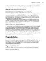
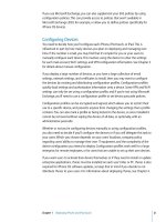
Figure 5-1 shows how LRE might be used in two typical multitenant buildings. The building on the
left uses existing but spare building wiring pairs to provide the LRE connection between a central
Catalyst 2900 LRE XL switch and a Cisco 575 LRE CPE unit in each tenant office. The building on
the right has an existing PBX that provides telephone services to the tenants. LRE is provided over
the same telephone wiring through a central LRE 48-port POTS splitter. Then, a Catalyst 2900 LRE
XL connects to multiple Cisco 575 units over the existing cabling.
Figure 5-1 Typical LRE Installation
Fast Ethernet
Rather than require campuses to invest in a completely new technology to gain increased bandwidth,
the networking industry developed a higher-speed Ethernet based on existing Ethernet standards.
PBX
Catalyst
2900 LRE XL
Catalyst
2900 LRE XL
LRE 48
POTS Splitter
LRE
575
LRE CPE
Tenant Offices or Rooms
575
LRE CPE
LRE LRE
575
LRE CPE
575
LRE CPE
PSTN
1-58720-077-5.book Page 114 Tuesday, August 19, 2003 3:16 PM
Ethernet Concepts 115
Fast Ethernet operates at 100 Mbps and is defined in the IEEE 802.3u standard. The Ethernet cabling
schemes, CSMA/CD operation, and all upper-layer protocol operations are maintained with Fast
Ethernet. The net result is the same data link Media Access Control (MAC) layer merged with a new
physical layer.
The campus network can use Fast Ethernet to link access and distribution layer switches, if no
higher-speed links are available. These links can support the aggregate traffic from multiple Ethernet
segments in the access layer. Fast Ethernet is generally used to connect end user workstations to the
access layer switch and to provide improved connectivity to enterprise servers.
Cabling for Fast Ethernet can involve either UTP or fiber. Table 5-2 lists the specifications for Fast
Ethernet that define the media types and distances.
Full-Duplex Fast Ethernet
As with traditional Ethernet, the natural progression to improve performance is to use full-duplex
operation. Fast Ethernet can provide 100 Mbps in each direction on a switched connection, for
200 Mbps total throughput. This throughput is possible only when a workstation, server, or a router
directly connects to a switch port, or when two switches directly connect to each other. In any case,
the operating system or firmware on each end of the connection must support full-duplex operation.
The Fast Ethernet specification also offers backward-compatibility to support traditional 10-Mbps
Ethernet. In the case of 100BASE-TX, switch ports are often called “10/100” ports, to denote the
dual speed. To provide this support, the two devices at each end of a network connection can
automatically negotiate link capabilities so that they can both operate at a maximum common level.
This negotiation involves detecting and selecting the highest physical layer technology (available
bandwidth) and half-duplex or full-duplex operation. To properly negotiate a connection, both ends
should be configured for autonegotiation.
Table 5-2 Cabling Specifications for Fast Ethernet
Technology Wiring Type Pairs Cable Length
100BASE-TX EIA/TIA Category 5 UTP 2 100 m
100BASE-T2 EIA/TIA Category 3,4,5 UTP 2 100 m
100BASE-T4 EIA/TIA Category 3,4,5 UTP 4 100 m
100BASE-FX Multimode fiber (MMF); 62.5 micron core,
125 micron outer cladding (62.5/125)
1 400 m half duplex or 2000 m
full duplex
Single-mode fiber (SMF) 1 10 km
1-58720-077-5.book Page 115 Tuesday, August 19, 2003 3:16 PM
116 Chapter 5: Switch Port Configuration
The link speed is determined by electrical signaling, so that either end of a link can determine what
the other end is trying to use. If both ends of the link are configured to autonegotiate, they will use
the highest speed that is common to them.
A link’s duplex mode, however, is negotiated through an exchange of information. This means that
for one end to successfully autonegotiate the duplex mode, the other end must also be set to auto-
negotiate. Otherwise, one end will never see any duplex information from the other end and won’t
determine the correct common mode. If duplex autonegotiation fails, a switch port falls back to its
default setting—half-duplex. Beware of a duplex mismatch when both ends of a link are not set for
autonegotiation.
Autonegotiation uses the priorities shown in Table 5-3 for each mode of Ethernet to determine which
technology to agree upon. If both devices can support more than one technology, the technology
with the highest priority is used. For example, if two devices can support both 10BASE-T and
100BASE-TX, both devices will use the higher priority 100BASE-TX mode.
To assure proper configuration at both ends of a link, Cisco recommends that the appropriate values
for transmission speed and duplex mode be manually configured on switch ports. This precludes any
possibility that one end of the link will change its settings, resulting in an unusable connection.
Cisco provides one additional capability to Fast Ethernet, which allows several Fast Ethernet links
to be bundled together for increased throughput. Fast EtherChannel (FEC) allows two to eight full-
duplex Fast Ethernet links to act as a single physical link, for 400- to 1600-Mbps duplex bandwidth.
This technology is described in greater detail in Chapter 8, “Aggregating Switch Links.”
For further reading about Fast Ethernet technology, refer to the article, “Fast Ethernet 100-Mbps
Solutions,” at Cisco’s website: www.cisco.com/warp/public/cc/so/neso/lnso/lnmnso/feth_tc.htm.
Table 5-3 Autonegotiation Selection Priorities
Priority Ethernet Mode
7 100BASE-T2 (full duplex)
6 100BASE-TX (full duplex)
5 100BASE-T2 (half duplex)
4 100BASE-T4
3 100BASE-TX
2 10BASE-T (full duplex)
1 10BASE-T
1-58720-077-5.book Page 116 Tuesday, August 19, 2003 3:16 PM
Ethernet Concepts 117
Gigabit Ethernet
You can scale Fast Ethernet by an additional order of magnitude with Gigabit Ethernet (which
supports 1000 Mbps or 1 Gbps), using the same IEEE 802.3 Ethernet frame format as before. This
scalability allows network designers and managers to leverage existing knowledge and technologies
to install, migrate, manage, and maintain Gigabit Ethernet networks.
However, the physical layer has been modified to increase data transmission speeds. Two technologies
were merged together to gain the benefits of each: the IEEE 802.3 Ethernet standard and the Amer-
ican National Standards Institute (ANSI) X3T11 FibreChannel. IEEE 802.3 provided the foundation
of frame format, CSMA/CD, full duplex, and other Ethernet characteristics. FibreChannel provided
a base of high-speed ASICs, optical components, and encoding/decoding and serialization mechanisms.
The resulting protocol is termed IEEE 802.3z Gigabit Ethernet.
Gigabit Ethernet supports several cabling types, referred to as 1000BASE-X. Table 5-4 lists the cabling
specifications for each type.
In a campus network, you can use Gigabit Ethernet in the switch block, core block, and server block.
In the switch block, it connects access layer switches to distribution layer switches. In the core, it
connects the distribution layer to the core switches and interconnects the core devices. In a server
block, a Gigabit Ethernet switch can provide high-speed connections to individual servers.
Table 5-4 Gigabit Ethernet Cabling and Distance Limitations
GE Type Wiring Type Pairs Cable Length
1000BASE-CX Shielded twisted-pair (STP) 1 25 m
1000BASE-T EIA/TIA Category 5 UTP 4 100 m
1000BASE-SX Multimode fiber (MMF) with 62.5 micron core;
850 nm laser
1 275 m
MMF with 50 micron core; 850 nm laser 1 550 m
1000BASE-LX/LH MMF with 62.5 micron core; 1300 nm laser 1 550 m
Single-mode fiber (SMF) with 50 micron core;
1300 nm laser
1 550 m
SMF with 9 micron core; 1300 nm laser 1 10 km
1000BASE-ZX SMF with 9 micron core; 1550 nm laser 1 70 km
SMF with 8 micron core; 1550 nm laser 1 100 km
1-58720-077-5.book Page 117 Tuesday, August 19, 2003 3:16 PM