ccnp 642 811 bcmsn exam certification guide second edition phần 5 ppt
Bạn đang xem bản rút gọn của tài liệu. Xem và tải ngay bản đầy đủ của tài liệu tại đây (2.24 MB, 63 trang )
IEEE 802.1D Overview 219
An election process among all connected switches chooses the Root Bridge. Each switch has a
unique Bridge ID that identifies it to other switches. The Bridge ID is an 8-byte value consisting of
the following fields:
■ Bridge Priority (2 bytes)—The priority or weight of a switch in relation to all other switches.
The priority field can have a value of 0 to 65,535 and defaults to 32,768 (or 0x8000) on every
Catalyst switch.
■ MAC Address (6 bytes)—The MAC address used by a switch can come from the Supervisor
module, the backplane, or a pool of 1024 addresses that are assigned to every Supervisor or
backplane depending on the switch model. In any event, this address is hardcoded and unique,
and the user cannot change it.
When a switch first powers up, it has a narrow view of its surroundings and assumes that it is
the Root Bridge itself. This notion will probably change as other switches check in and enter the
election process. The election process then proceeds as follows: Every switch begins by sending out
BPDUs with a Root Bridge ID equal to its own Bridge ID and a Sender Bridge ID of its own Bridge
ID. The Sender Bridge ID simply tells other switches who is the actual sender of the BPDU
message. (After a Root Bridge is decided upon, configuration BPDUs are only sent by the Root
Bridge. All other bridges must forward or relay the BPDUs, adding their own Sender Bridge IDs
to the message.)
Received BPDU messages are analyzed to see if a “better” Root Bridge is being announced. A Root
Bridge is considered better if the Root Bridge ID value is lower than another. Again, think of the
Root Bridge ID as being broken up into Bridge Priority and MAC address fields. If two Bridge
Priority values are equal, the lower MAC address makes the Bridge ID better. When a switch hears
of a better Root Bridge, it replaces its own Root Bridge ID with the Root Bridge ID announced in
the BPDU. The switch is then required to recommend or advertise the new Root Bridge ID in its
own BPDU messages; although, it will still identify itself as the Sender Bridge ID.
Sooner or later, the election converges and all switches agree on the notion that one of them is the
Root Bridge. As might be expected, if a new switch with a lower Bridge Priority powers up, it begins
advertising itself as the Root Bridge. Because the new switch does indeed have a lower Bridge ID,
all the switches will soon reconsider and record it as the new Root Bridge. This can also happen if
the new switch has a Bridge Priority equal to the existing Root Bridge but a lower MAC address.
Root Bridge election is an ongoing process, triggered by Root Bridge ID changes in the BPDUs
every two seconds.
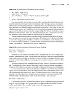
As an example, consider the small network shown in Figure 9-3. For simplicity, assume that each
Catalyst switch has a MAC address of all 0s with the last hex digit equal to the switch label.
1-58720-077-5.book Page 219 Tuesday, August 19, 2003 3:16 PM
220 Chapter 9: Traditional Spanning Tree Protocol
Figure 9-3 Example of Root Bridge Election
In this network, each switch has the default Bridge Priority of 32,768. The switches are
interconnected with FastEthernet links, having a default path cost of 19. All three switches try to
elect themselves as the Root, but all of them have equal Bridge Priority values. The election is
determined by the lowest MAC address—that of Catalyst A.
Electing Root Ports
Now that a reference point has been nominated and elected for the entire switched network, each
nonroot switch must figure out where it is in relation to the Root Bridge. This action can be
performed by selecting only one Root Port on each nonroot switch.
STP uses the concept of cost to determine many things. Selecting a Root Port involves evaluating
the Root Path Cost. This value is the cumulative cost of all the links leading to the Root Bridge. A
particular switch link has a cost associated with it, too, called the Path Cost. To understand the
difference between these values, remember that only the Root Path Cost is carried inside the BPDU.
(See Table 9-2 again.) As the Root Path Cost travels along, other switches can modify its value to
make it cumulative. The Path Cost, however, is not contained in the BPDU. It is known only to the
local switch where the port (or “path” to a neighboring switch) resides.
Catalyst A
32768.00-00-00-00-00-0a
Root Bridge
1/1
1/2
1/2
1/2
1/1
1/1
100 Mbps
Cost = 19
100 Mbps
Cost = 19
100 Mbps
Cost = 19
Catalyst B
32768.00-00-00-00-00-0b
Catalyst C
32768.00-00-00-00-00-0c
1-58720-077-5.book Page 220 Tuesday, August 19, 2003 3:16 PM
IEEE 802.1D Overview 221
Path Costs are defined as a 1-byte value, with the default values shown in Table 9-3. Generally, the
higher the bandwidth of a link, the lower the cost of transporting data across it. The original IEEE
802.1D standard defined Path Cost as 1000 Mbps divided by the link bandwidth in Mbps. These val-
ues are shown in the center column of the table. Modern networks commonly use GigabitEthernet
and OC-48 ATM, which are both either too close to or greater than the maximum scale of 1000 Mbps.
The IEEE now uses a nonlinear scale for Path Cost, as shown in the right column of the table.
The Root Path Cost value is determined in the following manner:
1. The Root Bridge sends out a BPDU with a Root Path Cost value of 0 because its ports sit
directly on the Root Bridge.
2. When the next-closest neighbor receives the BPDU, it adds the Path Cost of its own port where
the BPDU arrived. (This is done as the BPDU is received.)
3. The neighbor sends out BPDUs with this new cumulative value as the Root Path Cost.
4. This value is added to by subsequent switch port Path Costs as each switch receives the BPDU
on down the line.
TIP Be aware that there are two STP path cost scales—one that is little used with a linear scale
and one commonly used that is nonlinear. If you decide to memorize some common Path Cost
values, learn only the ones in the “new” righthand column of the table.
Table 9-3 STP Path Cost
Link Bandwidth Old STP Cost New STP Cost
4 Mbps 250 250
10 Mbps 100 100
16 Mbps 63 62
45 Mbps 22 39
100 Mbps 10 19
155 Mbps 6 14
622 Mbps 2 6
1 Gbps 1 4
10 Gbps 0 2
1-58720-077-5.book Page 221 Tuesday, August 19, 2003 3:16 PM
222 Chapter 9: Traditional Spanning Tree Protocol
After incrementing the Root Path Cost, a switch also records the value in its memory. When a BPDU
is received on another port and the new Root Path Cost is lower than the previously recorded value,
this lower value becomes the new Root Path Cost. In addition, the lower cost tells the switch that
the path to the Root Bridge must be better using this port than it was on other ports. The switch has
now determined which of its ports has the best path to the Root—the Root Port.
Figure 9-4 shows the same network from Figure 9-3 in the process of Root Port selection.
Figure 9-4 Example of Root Port Selection
The Root Bridge, Catalyst A, has already been elected. Therefore, every other switch in the network
must choose one port that has the best path to the Root Bridge. Catalyst B selects its port 1/1, with
a Root Path Cost of 0 plus 19. Port 1/2 is not chosen because its Root Path Cost is 0 (BPDU from
Catalyst A) plus 19 (Path Cost of A-C link) plus 19 (Path Cost of C-B link), or a total of 38. Catalyst
C makes a similar choice of port 1/1.
NOTE Notice the emphasis on incrementing the Root Path Cost as BPDUs are received. When
computing the Spanning Tree Algorithm manually, remember to compute a new Root Path Cost
as BPDUs come in to a switch port—not as they go out.
Catalyst A
32768.00-00-00-00-00-0a
Root Bridge
1/1
1/2
1/2
1/2
1/1
1/1
100 Mbps
Cost = 19
100 Mbps
Cost = 19
100 Mbps
Cost = 19
Catalyst B
32768.00-00-00-00-00-0b
Catalyst C
32768.00-00-00-00-00-0c
Root Port
Root Port
Root Path Cost = 19
Root Path Cost = 19
(Root Path Cost = 19 + 19)
1-58720-077-5.book Page 222 Tuesday, August 19, 2003 3:16 PM
IEEE 802.1D Overview 223
Electing Designated Ports
By now, you should begin to see the process unfolding: a starting or reference point has been
identified, and each switch “connects” itself toward the reference point with the single link that has
the best path. A tree structure is beginning to emerge, but links have been identified only at this
point. All links are still connected and could be active, leaving bridging loops.
To remove the possibility of bridging loops, STP makes a final computation to identify one Desig-
nated Port on each network segment. Suppose that two or more switches have ports connected to a
single common network segment. If a frame appears on that segment, all the bridges attempt to for-
ward it to its destination. Recall that this behavior was the basis of a bridging loop and should be
avoided.
Instead, only one of the links on a segment should forward traffic to and from that segment. This
location is the Designated Port. Switches choose a Designated Port based on the lowest cumulative
Root Path Cost to the Root Bridge. For example, a switch always has an idea of its own Root Path
Cost, which it announces in its own BPDUs. If a neighboring switch on a shared LAN segment
sends a BPDU announcing a lower Root Path Cost, the neighbor must have the Designated Port.
If a switch learns only of higher Root Path Costs from other BPDUs received on a port, however,
it then correctly assumes that its own receiving port is the Designated Port for the segment.
Notice that the entire STP determination process has served only to identify bridges and ports. All
ports are still active, and bridging loops might still lurk in the network. STP has a set of progressive
states that each port must go through, regardless of the type or identification. These states actively
prevent loops from forming and are described in the next section.
Figure 9-5 demonstrates an example of Designated Port selection. This figure is identical to Figure 9-3
and Figure 9-4, with further Spanning Tree development. The only changes shown are the choices
of Designated Ports, although seeing all STP decisions shown in one network diagram is handy.
NOTE In each determination process discussed so far, two or more links having identical Root
Path Costs is possible. This results in a tie condition, unless other factors are considered. All STP
decisions are based on the following sequence of four conditions:
1. Lowest Root Bridge ID
2. Lowest Root Path Cost to Root Bridge
3. Lowest Sender Bridge ID
4. Lowest Sender Port ID
1-58720-077-5.book Page 223 Tuesday, August 19, 2003 3:16 PM
224 Chapter 9: Traditional Spanning Tree Protocol
Figure 9-5 Example of Designated Port Selection
The three switches have chosen their Designated Ports (DP) for the following reasons:
■ Catalyst A—Because this switch is the Root Bridge, all its active ports are Designated Ports
by definition. At the Root Bridge, the Root Path Cost of each port is 0.
■ Catalyst B—Catalyst A port 1/1 is the DP for the Segment A-B because it has the lowest Root
Path Cost (0). Catalyst B port 1/2 is the DP for segment B-C. The Root Path Cost for each end
of this segment is 19, determined from the incoming BPDU on port 1/1. Because the Root Path
Cost is equal on both ports of the segment, the DP must be chosen by the next criteria—the
lowest Sender Bridge ID. When Catalyst B sends a BPDU to Catalyst C, it has the lowest MAC
address in the Bridge ID. Catalyst C also sends a BPDU to Catalyst B, but its Sender Bridge ID
is higher. Therefore, Catalyst B port 1/2 is selected as the segment’s DP.
Catalyst A
32768.00-00-00-00-00-0a
Designated
Port
1/1
1/2
1/2
1/2
1/1
1/1
100 Mbps
Cost = 19
100 Mbps
Cost = 19
100 Mbps
Cost = 19
Catalyst B
32768.00-00-00-00-00-0b
Catalyst C
32768.00-00-00-00-00-0c
Root Port
Root Port
Root Path Cost = 19
Root Path Cost = 19
Both Root Path Cost = 19
Catalyst B has lowest Bridge ID
Root Bridge
Designated
Port
Root Path Cost = 0
Designated
Port
X
Root Path Cost = 0
1-58720-077-5.book Page 224 Tuesday, August 19, 2003 3:16 PM
IEEE 802.1D Overview 225
■ Catalyst C—Catalyst A port 1/2 is the DP for Segment A-C because it has the lowest Root Path
Cost (0). Catalyst B port 1/2 is the DP for Segment B-C. Therefore, Catalyst C port 1/2 will be
neither a Root Port nor a Designated Port. As discussed in the next section, any port that is not
elected to either position enters the Blocking state. Where blocking occurs, bridging loops are
broken.
STP States
To participate in STP, each port of a switch must progress through several states. A port begins its
life in a Disabled state, moving through several passive states and, finally, into an active state if
allowed to forward traffic. The STP port states are as follows:
■ Disabled—Ports that are administratively shut down by the network administrator, or by the
system due to a fault condition, are in the Disabled state. This state is special and is not part of
the normal STP progression for a port.
■ Blocking—After a port initializes, it begins in the Blocking state so that no bridging loops can
form. In the Blocking state, a port cannot receive or transmit data and cannot add MAC
addresses to its address table. Instead, a port is allowed to receive only BPDUs so that the
switch can hear from other neighboring switches. In addition, ports that are put into standby
mode to remove a bridging loop enter the Blocking state.
■ Listening—The port will be moved from Blocking to Listening if the switch thinks that the port
can be selected as a Root Port or Designated Port. In other words, the port is on its way to begin
forwarding traffic. In the Listening state, the port still cannot send or receive data frames.
However, the port is allowed to receive and send BPDUs so that it can actively participate in the
Spanning Tree topology process. Here, the port is finally allowed to become a Root Port or
Designated Port because the switch can advertise the port by sending BPDUs to other switches.
Should the port lose its Root Port or Designated Port status, it returns to the Blocking state.
■ Learning—After a period of time called the Forward Delay in the Listening state, the port is
allowed to move into the Learning state. The port still sends and receives BPDUs as before. In
addition, the switch can now learn new MAC addresses to add to its address table. This gives
the port an extra period of silent participation and allows the switch to assemble at least some
address table information.
■ Forwarding—After another Forward Delay period of time in the Learning state, the port is
allowed to move into the Forwarding state. The port can now send and receive data frames,
collect MAC addresses in its address table, and send and receive BPDUs. The port is now a fully
functioning switch port within the Spanning Tree topology.
NOTE Remember that a switch port is allowed into the Forwarding state only if no redundant
links (or loops) are detected and if the port has the best path to the Root Bridge as the Root Port
or Designated Port.
1-58720-077-5.book Page 225 Tuesday, August 19, 2003 3:16 PM
226 Chapter 9: Traditional Spanning Tree Protocol
Example 9-1 shows the output from a switch as one of its ports progresses through the STP port
states.
The example begins as the port is administratively disabled from the command line. When the port
is enabled, successive show spanning-tree interface type mod/port commands display the port
state as Listening, Learning, and then Forwarding. These are shown in the shaded text of the
example. Notice, also, the timestamps and port states provided by the debug spanning-tree switch
state command, which give a sense of the timing between port states. Because this port was eligible
as a Root Port, the show command was never able to execute fast enough to show the port in the
Blocking state.
Example 9-1 Port Progressing Through the STP Port States
*Mar 16 14:31:00 UTC: STP SW: Fa0/1 new disabled req for 1 vlans
Switch(config)# ii
ii
nn
nn
tt
tt
ee
ee
rr
rr
ff
ff
aa
aa
cc
cc
ee
ee
ff
ff
aa
aa
ss
ss
tt
tt
00
00
//
//
11
11
Switch(config-if)#nn
nn
oo
oo
ss
ss
hh
hh
uu
uu
tt
tt
Switch(config-if)#^^
^^
ZZ
ZZ
*Mar 16 14:31:00 UTC: STP SW: Fa0/1 new blocking req for 1 vlans
Switch#ss
ss
hh
hh
oo
oo
ww
ww
ss
ss
pp
pp
aa
aa
nn
nn
nn
nn
ii
ii
nn
nn
gg
gg
ii
ii
nn
nn
tt
tt
ee
ee
rr
rr
ff
ff
aa
aa
cc
cc
ee
ee
ff
ff
aa
aa
ss
ss
tt
tt
00
00
//
//
11
11
Vlan Port ID Designated Port ID
Name Prio.Nbr Cost Sts Cost Bridge ID Prio.Nbr
VLAN0001 128.1 19 LIS 0 32769 000a.f40a.2980 128.1
*Mar 16 14:31:15 UTC: STP SW: Fa0/1 new learning req for 1 vlans
Switch#ss
ss
hh
hh
oo
oo
ww
ww
ss
ss
pp
pp
aa
aa
nn
nn
nn
nn
ii
ii
nn
nn
gg
gg
ii
ii
nn
nn
tt
tt
ee
ee
rr
rr
ff
ff
aa
aa
cc
cc
ee
ee
ff
ff
aa
aa
ss
ss
tt
tt
00
00
//
//
11
11
Vlan Port ID Designated Port ID
Name Prio.Nbr Cost Sts Cost Bridge ID Prio.Nbr
VLAN0001 128.1 19 LRN 0 32768 00d0.5849.4100 32.129
*Mar 16 14:31:30 UTC: STP SW: Fa0/1 new forwarding req for 1 vlans
Switch#ss
ss
hh
hh
oo
oo
ww
ww
ss
ss
pp
pp
aa
aa
nn
nn
nn
nn
ii
ii
nn
nn
gg
gg
ii
ii
nn
nn
tt
tt
ee
ee
rr
rr
ff
ff
aa
aa
cc
cc
ee
ee
ff
ff
aa
aa
ss
ss
tt
tt
00
00
//
//
11
11
Vlan Port ID Designated Port ID
Name Prio.Nbr Cost Sts Cost Bridge ID Prio.Nbr
VLAN0001 128.1 19 FWD 0 32768 00d0.5849.4100 32.129
00
19 LIS
15
LRN
30
FWD
1-58720-077-5.book Page 226 Tuesday, August 19, 2003 3:16 PM
IEEE 802.1D Overview 227
STP Timers
STP operates as switches send BPDUs to each other in an effort to form a loop-free topology. The
BPDUs take a finite amount of time to travel from switch to switch. In addition, news of a topology
change (such as a link or Root Bridge failure) can suffer from propagation delays as the
announcement travels from one side of a network to the other. Because of the possibility of these
delays, keeping the Spanning Tree topology from settling out or converging until all switches have
had time to receive accurate information is important.
STP uses three timers to make sure that a network converges properly before a bridging loop can
form. The timers and their default values are as follows:
■ Hello Time—The time interval between Configuration BPDUs sent by the Root Bridge. The
Hello Time value configured in the Root Bridge switch determines the Hello Time for all
nonroot switches because they just relay the Configuration BPDUs as they are received from
the root. However, all switches have a locally configured Hello Time that is used to time TCN
BPDUs when they are retransmitted. The IEEE 802.1D standard specifies a default Hello Time
value of 2 seconds.
■ Forward Delay—The time interval that a switch port spends in both the Listening and
Learning states. The default value is 15 seconds.
■ Max (maximum) Age—The time interval that a switch stores a BPDU before discarding it.
While executing the STP, each switch port keeps a copy of the “best” BPDU that it has heard.
If the BPDU’s source loses contact with the switch port, the switch notices that a topology
change occurred after the Max Age time elapses and the BPDU is aged out. The default Max
Age value is 20 seconds.
The STP timers can be configured or adjusted from the switch command line. However, the timer
values should never be changed from the defaults without careful consideration. Then, the values
should be changed only on the Root Bridge switch. Recall that the timer values are advertised in
fields within the BPDU. The Root Bridge ensures that the timer values propagate to all other
switches.
NOTE The default STP timer values are based on some assumptions about the size of the network
and the length of the Hello Time. A reference model of a network having a diameter of seven
switches derives these values. The diameter is measured from the Root Bridge switch outward,
including the Root Bridge. In other words, if you drew the STP topology, the diameter would be
the number of switches connected in series from the Root Bridge out to the end of any branch in
the tree. The Hello Time is based on the time it takes for a BPDU to travel from the Root Bridge
to a point seven switches away. A Hello Time of 2 seconds is used in this computation.
1-58720-077-5.book Page 227 Tuesday, August 19, 2003 3:16 PM
228 Chapter 9: Traditional Spanning Tree Protocol
The network diameter can be configured on the Root Bridge switch to more accurately reflect the
true size of the physical network. Making that value more accurate reduces the total STP conver-
gence time during a topology change. Cisco also recommends that if changes need to be made, only
the network diameter value should be modified on the Root Bridge switch. When the diameter is
changed, the switch calculates new values for all three timers. This option is discussed in the
“Selecting the Root Bridge” section in Chapter 10.
Topology Changes
To announce a change in the active network topology, switches send a TCN BPDU. Table 9-4 shows
the format of these messages.
A topology change occurs when a switch either moves a port into the Forwarding state or moves a
port from Forwarding or Learning into the Blocking state. In other words, a port on an active switch
comes up or goes down. The switch sends a TCN BPDU out its Root Port so that, ultimately, the
Root Bridge receives news of the topology change. Notice that the TCN BPDU carries no data about
the change, but informs recipients only that a change has occurred. Also notice that the switch will
not send TCN BPDUs if the port has been configured with PortFast enabled.
The switch continues sending TCN BPDUs every Hello Time interval until it gets an
acknowledgment from an upstream neighbor. As the upstream neighbors receive the TCN BPDU,
they propagate it on toward the Root Bridge. When the Root Bridge receives the BPDU, the Root
Bridge also sends out an acknowledgment. However, it also sends out the Topology Change flag in
a Configuration BPDU so that all other bridges shorten their bridge table aging times from the
default (300 seconds) to only the Forward Delay value (default 15 seconds).
This condition causes the learned locations of MAC addresses to be flushed out much sooner than
they normally would, easing the bridge table corruption that might occur because of the change in
topology. However, any stations that are actively communicating during this time are kept in the
bridge table. This condition lasts for the sum of the Forward Delay and the Max Age (default 15 +
20 seconds).
Table 9-4 Topology Change Notification BPDU Message Content
Field Description # of Bytes
Protocol ID (always 0) 2
Version (always 0) 1
Message Type (Configuration
or TCN BPDU)
1
1-58720-077-5.book Page 228 Tuesday, August 19, 2003 3:16 PM
Types of STP 229
Types of STP
So far, this chapter has discussed STP in terms of its operation to prevent loops and to recover
from topology changes in a timely manner. STP was originally developed to operate in a bridged
environment, basically supporting a single LAN (or one VLAN). Implementing STP into a switched
environment has required additional consideration and modification to support multiple VLANs.
Because of this, the IEEE and Cisco have approached STP differently. This section reviews the three
traditional types of STP that are encountered in switched networks and how they relate to one
another. No specific configuration commands are associated with the various types of STP. Rather,
you need a basic understanding of how they interoperate in a network.
Common Spanning Tree (CST)
The IEEE 802.1Q standard specifies how VLANs are to be trunked between switches. It also
specifies only a single instance of STP for all VLANs. This instance is referred to as the Common
Spanning Tree (CST). All CST BPDUs are transmitted over the native VLAN as untagged frames.
Having a single STP for many VLANs simplifies switch configuration and reduces switch CPU load
during STP calculations. However, having only one STP instance can cause limitations, too. Redun-
dant links between switches will be blocked with no capability for load balancing. Conditions can
also occur that would cause forwarding on a link that does not support all VLANs, while other links
would be blocked.
Per-VLAN Spanning Tree (PVST)
Cisco has a proprietary version of STP that offers more flexibility than the CST version. Per-VLAN
Spanning Tree (PVST) operates a separate instance of STP for each individual VLAN. This allows
the STP on each VLAN to be configured independently, offering better performance and tuning for
specific conditions. Multiple Spanning Trees also make load balancing possible over redundant
links when the links are assigned to different VLANs.
Due to its proprietary nature, PVST requires the use of Cisco Inter-Switch Link (ISL) trunking
encapsulation between switches. In networks where PVST and CST coexist, interoperability
problems occur. Each requires a different trunking method, so BPDUs will never be exchanged
between STP types.
NOTE The IEEE has produced additional standards for Spanning Tree enhancements that greatly
improve on its scalability and convergence aspects. These are covered in Chapter 12, “Advanced
Spanning Tree Protocol.” After you have a firm understanding of the more traditional forms of
STP presented in this chapter, you can grasp the enhanced versions much easier.
1-58720-077-5.book Page 229 Tuesday, August 19, 2003 3:16 PM
230 Chapter 9: Traditional Spanning Tree Protocol
Per-VLAN Spanning Tree Plus (PVST+)
Cisco has a second proprietary version of STP that allows devices to interoperate with both PVST
and CST. Per-VLAN Spanning Tree Plus (PVST+) effectively supports three groups of STP
operating in the same campus network:
■ Catalyst switches running PVST
■ Catalyst switches running PVST+
■ Switches running CST over 802.1Q
To do this, PVST+ acts as a translator between groups of CST switches and groups of PVST
switches. PVST+ can communicate directly with PVST by using ISL trunks. To communicate with
CST, however, PVST+ exchanges BPDUs with CST as untagged frames over the native VLAN.
BPDUs from other instances of STP (other VLANs) are propagated across the CST portions of the
network by tunneling. PVST+ sends these BPDUs by using a unique multicast address so that the
CST switches forward them on to downstream neighbors without interpreting them first. Eventually,
the tunneled BPDUs reach other PVST+ switches where they are understood.
1-58720-077-5.book Page 230 Tuesday, August 19, 2003 3:16 PM
Foundation Summary 231
Foundation Summary
The Foundation Summary is a collection of information that provides a convenient review of many
key concepts in this chapter. If you are already comfortable with the topics in this chapter, this
summary can help you recall a few details. If you just read this chapter, this review should help
solidify some key facts. If you are doing your final preparation before the exam, this information is
a convenient way to review the day before the exam.
STP has a progression of states that each port moves through. Each state allows a port to do only
certain functions, as shown in Table 9-5.
Table 9-5 STP states and Port Activity
STP State The port can The port cannot Duration
Disabled Send or receive data N/A
Blocking Receive BPDUs Send or receive data or
learn MAC addresses
Indefinite if loop has been
detected
Listening Send and receive BPDUs Send or receive data or
learn MAC addresses
Forward Delay timer (15
seconds)
Learning Send and receive BPDUs
and learn MAC addresses
Send or receive data Forward Delay timer (15
seconds)
Forwarding Send and receive BPDUs,
learn MAC addresses, and
send and receive data
Indefinite as long as port is
up and loop is not detected
Table 9-6 Basic Spanning Tree Operation
Task Procedure
1. Elect Root Bridge. Lowest Bridge ID
2. Select Root Port (one per switch). Lowest Root Path Cost; if equal, use tie-breakers
3. Select Designated Port (one per segment). Lowest Root Path Cost; if equal, use tie-breakers
4. Block ports with loops. Block ports that are non-Root and non-Designated Ports
1-58720-077-5.book Page 231 Tuesday, August 19, 2003 3:16 PM
232 Chapter 9: Traditional Spanning Tree Protocol
To manually work out a Spanning Tree topology using a network diagram, follow the basic steps in
Table 9-7.
Table 9-7 Manual STP Computation
Task Description
1. Identify Path Costs on links. For each link between switches, write the Path Cost that
each switch uses for the link.
2. Identify Root Bridge. Find the switch with the lowest Bridge ID; mark it on the
drawing.
3. Select Root Ports (one per switch). For each switch, find the one port that has the best path to
the Root Bridge. This is the one with the lowest Root Path
Cost. Mark the port with an “RP” label.
4. Select Designated Ports (one per segment). For each link between switches, identify which end of the
link will be the Designated Port. This is the one with the
lowest Root Path Cost; if equal on both ends, use STP tie-
breakers. Mark the port with a “DP” label.
5. Identify the blocking ports. Every switch port that is neither a Root nor Designated
Port will be put into the Blocking state. Mark these with
an “X.”
Table 9-8 Spanning Tree Tie Breaker Criteria
Sequence Criteria
1 Lowest Root Bridge ID
2 Lowest Root Path Cost
3 Lowest Sender Bridge ID
4 Lowest Sender Port ID
Table 9-9 STP Path Cost
Link Bandwidth STP Cost (Nonlinear Scale)
4 Mbps 250
10 Mbps 100
16 Mbps 62
45 Mbps 39
1-58720-077-5.book Page 232 Tuesday, August 19, 2003 3:16 PM
Foundation Summary 233
100 Mbps 19
155 Mbps 14
622 Mbps 6
1 Gbps 4
10 Gbps 2
Table 9-10 STP Timers
Timer Function Default Value
Hello Interval between Configuration BPDUs. 2 seconds
Forward Delay Time spent in Listening and Learning states before transitioning
toward Forwarding state.
15 seconds
Max Age Maximum length of time a BPDU can be stored without receiving
an update; timer expiration signals an indirect failure with
Designated or Root Bridge.
20 seconds
Table 9-11 Types of STP
Type of STP Function
CST One instance of STP, over the native VLAN; 802.1Q-based
PVST One instance of STP per VLAN; Cisco ISL-based
PVST+ Provides interoperability between CST and PVST; operates over both 802.1Q and ISL
Table 9-9 STP Path Cost (Continued)
Link Bandwidth STP Cost (Nonlinear Scale)
1-58720-077-5.book Page 233 Tuesday, August 19, 2003 3:16 PM
234 Chapter 9: Traditional Spanning Tree Protocol
Q&A
The questions and scenarios in this book are more difficult than what you should experience on the
actual exam. The questions do not attempt to cover more breadth or depth than the exam; however,
they are designed to make sure that you know the answers. Rather than allowing you to derive the
answers from clues hidden inside the questions themselves, the questions challenge your understanding
and recall of the subject. Hopefully, these questions will help limit the number of exam questions
on which you narrow your choices to two options and then guess.
You can find the answers to these questions in Appendix A.
1. What is a bridging loop? Why is it bad?
2. Put the following STP port states in chronological order:
a. Learning
b. Forwarding
c. Listening
d. Blocking
3. Choose two types of STP messages used to communicate between bridges:
a. Advertisement BPDU
b. Configuration BPDU
c. ACK BPDU
d. TCN BPDU
4. What criteria are used to select the following?
a. Root Bridge
b. Root Port
c. Designated Port
d. Redundant (or secondary) Root Bridges
1-58720-077-5.book Page 234 Tuesday, August 19, 2003 3:16 PM
Q&A 235
5.
Which of the following switches become the Root Bridge, given the information in the
following table? Which switch becomes the secondary Root Bridge if the Root Bridge fails?
6. What conditions cause an STP topology change? What effect does this have on STP and the
network?
7. A Root Bridge has been elected in a switched network. Suppose a new switch is installed with
a lower Bridge ID than the existing Root Bridge. What will happen?
8. Suppose a switch receives Configuration BPDUs on two of its ports. Both ports are assigned to
the same VLAN. Each of the BPDUs announces Catalyst A as the Root Bridge. Can the switch
use both of these ports as Root Ports? Why?
9. How is the Root Path Cost calculated for a switch port?
10. What conditions can cause ports on a network’s Root Bridge to move into the Blocking state?
(Assume that all switch connections are to other switches. No crossover cables are used to
connect two ports together on the same switch.)
11. What parameters can be tuned to influence the selection of a port as a Root or Designated Port?
12. After a bridging loop forms, how can you stop the endless flow of traffic?
13. In a BPDU, when can the Root Bridge ID have the same value as the Sender Bridge ID?
14. Which of these is true about the Root Path Cost?
a. It is a value sent by the Root Bridge that cannot be changed along the way.
b. It is incremented as a switch receives a BPDU.
c. It is incremented as a switch sends a BPDU.
d. It is incremented by the Path Cost of a port.
Switch Name Bridge Priority MAC Address Port Costs
Catalyst A 32,768 00-d0-10-34-26-a0 All are 19
Catalyst B 32,768 00-d0-10-34-24-a0 All are 4
Catalyst C 32,767 00-d0-10-34-27-a0 All are 19
Catalyst D 32,769 00-d0-10-34-24-a1 All are 19
1-58720-077-5.book Page 235 Tuesday, August 19, 2003 3:16 PM
236 Chapter 9: Traditional Spanning Tree Protocol
15.
Suppose two switches are connected by a common link. Each must decide which one will have
the Designated Port on the link. Which switch takes on this role, if these STP advertisements
occur?
• The link is on switch A’s port number 12 and on switch B’s port number 5.
• Switch A has a Bridge ID of 32,768:0000.1111.2222, and switch B has
8192:0000.5555.6666.
• Switch A advertises a Root Path Cost of 8, while B advertises 12.
16. Using the default STP timers, how long does it take for a port to move from the Blocking state
to the Forwarding state?
17. If the Root Bridge sets the Topology Change flag in the BPDU, what must the other switches
in the network do?
18. Over what VLAN(s) does the CST form of STP run?
a. VLAN 1
b. All active VLANs
c. All VLANs (active or inactive)
d. The native VLAN
19. What is the major difference between PVST and PVST+?
20. Two switches are connected by a common active link. When might neither switch have a
Designated Port on the link?
a. When neither has a better Root Path Cost.
b. When the switches are actually the primary and secondary Root Bridges.
c. When one switch has its port in the Blocking state.
d. Never; this can’t happen.
1-58720-077-5.book Page 236 Tuesday, August 19, 2003 3:16 PM
1-58720-077-5.book Page 237 Tuesday, August 19, 2003 3:16 PM
This chapter covers the
following topics that you
need to master for the CCNP
BCMSN exam:
■ STP Root Bridge—This section discusses
the importance of identifying a Root Bridge,
as well as suggestions for its placement in the
network. This section also presents the Root
Bridge configuration commands.
■ Spanning Tree Customization—This
section covers the configuration commands
that allow you to alter the spanning tree’s
topology.
■ Tuning Spanning Tree Convergence—This
section discusses how to alter, or tune, the
STP timers to achieve optimum convergence
times in a network.
■ Redundant Link Convergence—This
section describes the methods that cause a
network to converge more quickly after a
topology change.
■ Troubleshooting STP—This section offers a
brief summary of the commands you can use
to verify that an STP instance is working
properly.
1-58720-077-5.book Page 238 Tuesday, August 19, 2003 3:16 PM
C H A P T E R
10
Spannning Tree Configuration
This chapter presents the design and configuration considerations necessary to implement the
IEEE 802.1D Spanning Tree Protocol (STP) in a campus network. This chapter also provides a
refresher on the commands needed to configure the STP features, as previously described in
Chapter 9, “Traditional Spanning Tree Protocol.”
You can also tune STP or make it converge more efficiently in a given network. This chapter
presents the theory and commands needed to accomplish this.
“Do I Know This Already?” Quiz
The purpose of the “Do I Know This Already?” quiz is to help you decide what parts of this
chapter to use. If you already intend to read the entire chapter, you do not necessarily need to
answer these questions now.
The quiz, derived from the major sections in the “Foundation Topics” portion of the chapter,
helps you determine how to spend your limited study time.
Table 10-1 outlines the major topics discussed in this chapter and the “Do I Know This
Already?” quiz questions that correspond to those topics.
Table 10-1 “Do I Know This Already?” Foundation Topics Section-to-Question Mapping
Foundation Topics Section Questions Covered in This Section
STP Root Bridge 1–5
Spanning Tree Customization 6–7
Tuning Spanning Tree Convergence 8–9
Redundant Link Convergence 10–12
CAUTION The goal of self-assessment is to gauge your mastery of the topics in this chapter.
If you do not know the answer to a question or are only partially sure of the answer, you
should mark this question wrong. Giving yourself credit for an answer you correctly guess
skews your self-assessment results and might give you a false sense of security.
1-58720-077-5.book Page 239 Tuesday, August 19, 2003 3:16 PM
240 Chapter 10: Spannning Tree Configuration
1.
Where should the Root Bridge be placed on a network?
a. On the fastest switch
b. Closest to the most users
c. Closest to the center of the network
d. On the least-used switch
2. Which of the following is a result of a poorly placed Root Bridge in a network?
a. Bridging loops form.
b. STP topology can’t be resolved.
c. STP topology can take unexpected paths.
d. Root Bridge election flapping.
3. Which of these parameters should you change to make a switch become a Root Bridge?
a. Switch MAC address
b. Path Cost
c. Port Priority
d. Bridge Priority
4. What is the default STP Bridge Priority on a Catalyst switch?
a. 0
b. 1
c. 32,768
d. 65,535
5. Which of the following commands can make a switch become the Root Bridge for VLAN 5,
assuming that all switches have the default STP parameters?
a. spanning-tree root
b. spanning-tree root vlan 5
c. spanning-tree vlan 5 priority 100
d. spanning-tree vlan 5 root
1-58720-077-5.book Page 240 Tuesday, August 19, 2003 3:16 PM
“Do I Know This Already?” Quiz 241
6.
What is the default Path Cost of a Gigabit Ethernet switch port?
a. 1
b. 2
c. 4
d. 19
e. 1000
7. What command can change the Path Cost of interface Gigabit Ethernet 3/1 to a value of 8?
a. spanning-tree path-cost 8
b. spanning-tree cost 8
c. spanning-tree port-cost 8
d. spanning-tree gig 3/1 cost 8
8. What happens if the Root Bridge switch and another switch are configured with different STP
hello timer values?
a. Nothing; each sends hellos at different times.
b. A bridging loop could form because the two switches are out of sync.
c. The switch with the lower hello timer becomes the Root Bridge.
d. The other switch changes its hello timer to match the Root Bridge.
9. What network diameter value is the basis for the default STP timer calculations?
a. 1
b. 3
c. 7
d. 9
e. 15
10. Where should the STP PortFast feature be used?
a. An access layer switch port connected to a PC
b. An access layer switch port connected to a hub
c. A distribution layer switch port connected to an access layer switch
d. A core layer switch port
1-58720-077-5.book Page 241 Tuesday, August 19, 2003 3:16 PM
242 Chapter 10: Spannning Tree Configuration
11.
Where should the STP UplinkFast feature be enabled?
a. An access layer switch
b. A distribution layer switch
c. A core layer switch
d. All of the above
12. If used, the STP BackboneFast feature should be enabled on which of these?
a. All backbone or core layer switches
b. All backbone and distribution layer switches
c. All access layer switches
d. All switches in the network
The answers to the “Do I Know This Already?” quiz are found in Appendix A, “Answers to Chapter
‘Do I Know This Already?’ Quizzes and Q&A Sections.” The suggested choices for your next step
are as follows:
■ 10 or less overall score—Read the entire chapter. This includes the “Foundation Topics,”
“Foundation Summary,” and “Q&A” sections.
■ 11 or 12 overall score—If you want more review on these topics, skip to the “Foundation
Summary” section and then go to the “Q&A” section at the end of the chapter. Otherwise, move
to Chapter 11, “Protecting the Spanning Tree Protocol Topology.”
1-58720-077-5.book Page 242 Tuesday, August 19, 2003 3:16 PM
STP Root Bridge 243
Foundation Topics
STP Root Bridge
STP and its computations are predictable; however, other factors exist that might subtly influence
STP decisions, making the resulting tree structure neither expected nor ideal.
The network administrator can make adjustments to the Spanning Tree operation to control its
behavior. The location of the Root Bridge should be determined as part of the design process. You
can also use redundant links for load balancing in parallel, if configured correctly. You can also
configure Spanning Tree Protocol (STP) to converge quickly and predictably in the event of a major
topology change.
Root Bridge Placement
While STP is wonderfully automatic with its default values and election processes, the resulting tree
structure might perform quite differently than expected. The Root Bridge election is based on the
idea that one switch is chosen as a common reference point, and all other switches choose ports that
have the best cost path to the Root. The Root Bridge election is also based on the idea that the Root
Bridge can become a central hub that interconnects other legs of the network. Therefore, the Root
Bridge can be faced with heavy switching loads in its central location.
If the Root Bridge election is left to its default state, several things can occur to make a poor choice.
For example, the slowest switch (or bridge) can be elected as the Root Bridge. If heavy traffic loads
are expected to pass through the Root Bridge, the slowest switch is not the ideal candidate. Recall
that the only criteria for Root Bridge election is the lowest Bridge ID (Bridge Priority and MAC
address)—not necessarily the best choice to ensure optimal performance. If the slowest switch has
the same Bridge Priority as the others and has the lowest MAC address, the slowest switch will be
chosen as the Root.
A second factor to consider relates to redundancy. If all switches are left to their default states, only
one Root Bridge is elected with no clear choice for a “backup.” What happens if that switch fails?
Another Root Bridge election occurs, but again, the choice might not be the ideal switch or the ideal
location.
NOTE By default, STP is enabled on all ports of a switch. STP should remain enabled in a
network to prevent bridging loops from forming. However, if STP has been disabled, you can
re-enabled it with the following global configuration command:
Switch (config)# spanning-tree vlan
vlan-id
1-58720-077-5.book Page 243 Tuesday, August 19, 2003 3:16 PM