ccnp 642 811 bcmsn exam certification guide second edition phần 9 pot
Bạn đang xem bản rút gọn của tài liệu. Xem và tải ngay bản đầy đủ của tài liệu tại đây (2.3 MB, 63 trang )
“Do I Know This Already?” Quiz 471
6.
The vlan 100 command has just been entered. What is the next command needed to configure
VLAN 100 as a secondary isolated VLAN?
a. private-vlan isolated
b. private-vlan isolated 100
c. pvlan secondary isolated
d. No further configuration is necessary.
7. What type of port configuration should you use for private VLAN interfaces on a router?
a. Host
b. Gateway
c. Promiscuous
d. Transparent
8. Promiscuous ports must be to primary and secondary VLANs, and
host ports must be .
a. mapped, associated
b. mapped, mapped
c. associated, mapped
d. associated, associated
9. Which of the following allows a port to be mirrored to another port on the same switch?
a. VSPAN
b. RSPAN
c. SPAN
d. CSPAN
10. What must be used to connect switches used for RSPAN?
a. An 802.1Q trunk
b. Access-mode switch ports (single VLAN)
c. A private VLAN over a trunk
d. An RSPAN VLAN over a trunk
1-58720-077-5.book Page 471 Tuesday, August 19, 2003 3:16 PM
472 Chapter 20: Securing with VLANs
11.
What is the most important difference between an RSPAN VLAN and a regular VLAN?
a. The RSPAN VLAN disables MAC address learning.
b. The RSPAN VLAN uses static MAC address definitions.
c. The RSPAN VLAN has the RSPAN source and destination MAC addresses defined in the
CAM table.
d. The RSPAN VLAN cannot be carried over a trunk link.
12. To configure an RSPAN session’s source switch, what is used for the session destination?
a. The switch port leading to the destination switch
b. The RSPAN VLAN
c. The final destination switch port
d. The next-hop router
The answers to the “Do I Know This Already?” quiz are found in Appendix A, “Answers to Chapter
‘Do I Know This Already?’ Quizzes and Q&A Sections.” The suggested choices for your next step
are as follows:
■ 10 or less overall score—Read the entire chapter. This includes the “Foundation Topics,”
“Foundation Summary,” and “Q&A” sections.
■ 11 or 12 overall score—If you want more review on these topics, skip to the “Foundation
Summary” section and then go to the “Q&A” section at the end of the chapter. Otherwise, move
to Chapter 21, “Scenarios for Final Preparation.”
1-58720-077-5.book Page 472 Tuesday, August 19, 2003 3:16 PM
VLAN Access Lists 473
Foundation Topics
VLAN Access Lists
Access lists can manage or control traffic as it passes through a switch. When normal access lists
are configured on a Catalyst switch, they filter traffic through the use of the Ternary Content
Addressable Memory (TCAM). Recall from Chapter 3, “Switch Operation,” that access lists (also
known as router access lists or RACLs) are merged or compiled into the TCAM. Each ACL is
applied to an interface according to the direction of traffic—inbound or outbound. Packets can then
be filtered in hardware with no switching performance penalty. However, only packets that pass
between VLANs can be filtered this way.
Packets that stay in the same VLAN do not ever cross a VLAN or interface boundary and do not
necessarily have a direction in relation to an interface. These packets might also be non-IP, non-IPX,
or completely bridged; therefore, they never pass through the multilayer switching mechanism.
VLAN access lists (VACLs) are filters that can directly affect how packets are handled within
a VLAN.
VACLs are somewhat different from RACLs or traditional access control lists. Although they too
are merged into the TCAM, they can permit, deny, or redirect packets as they are matched. VACLs
are also configured in a route map fashion, with a series of matching conditions and actions to take.
VACL Configuration
VACLs are configured as a VLAN access map, in much the same format as a route map. A VLAN
access map consists of one or more statements, each having a common map name. First, you define
the VACL with the following global configuration command:
Switch(config)# vv
vv
ll
ll
aa
aa
nn
nn
aa
aa
cc
cc
cc
cc
ee
ee
ss
ss
ss
ss
mm
mm
aa
aa
pp
pp
map-name
[
sequence-number
]
Access map statements are evaluated in sequence, according to the sequence-number. Each
statement can contain one or more matching conditions, followed by an action.
Next, define the matching conditions that identify the traffic to be filtered. Matching is performed
by access lists (IP, IPX, or MAC address ACLs), which you must configure independently. Config-
ure a matching condition with the following access map configuration command:
Switch(config-access-map)# mm
mm
aa
aa
tt
tt
cc
cc
hh
hh
{ii
ii
pp
pp
aa
aa
dd
dd
dd
dd
rr
rr
ee
ee
ss
ss
ss
ss
{
acl-number
|
acl-name
}} | {ii
ii
pp
pp
xx
xx
aa
aa
dd
dd
dd
dd
rr
rr
ee
ee
ss
ss
ss
ss
{
acl-number
|
acl-name
}} | {mm
mm
aa
aa
cc
cc
aa
aa
dd
dd
dd
dd
rr
rr
ee
ee
ss
ss
ss
ss
acl-name
}
1-58720-077-5.book Page 473 Tuesday, August 19, 2003 3:16 PM
474 Chapter 20: Securing with VLANs
You can repeat this command to define several matching conditions; the first match encountered
triggers an action to take. Define the action with the following access map configuration command:
Switch(config-access-map)# aa
aa
cc
cc
tt
tt
ii
ii
oo
oo
nn
nn
{dd
dd
rr
rr
oo
oo
pp
pp
| ff
ff
oo
oo
rr
rr
ww
ww
aa
aa
rr
rr
dd
dd
[cc
cc
aa
aa
pp
pp
tt
tt
uu
uu
rr
rr
ee
ee
] | rr
rr
ee
ee
dd
dd
ii
ii
rr
rr
ee
ee
cc
cc
tt
tt
interface type
mod/num
}
A VACL can either drop a matching packet, forward it, or redirect it to another interface. The
TCAM performs the entire VACL match and action, as packets are switched or bridged within a
VLAN, or routed into or out of a VLAN.
Finally, you must apply the VACL to a VLAN interface using the following global configuration
command:
Switch(config)# vv
vv
ll
ll
aa
aa
nn
nn
ff
ff
ii
ii
ll
ll
tt
tt
ee
ee
rr
rr
map-name
vv
vv
ll
ll
aa
aa
nn
nn
ll
ll
ii
ii
ss
ss
tt
tt
vlan-list
Notice that the VACL is applied globally to one or more VLANs listed and not to a VLAN interface
(SVI). Recall that VLANs can be present in a switch as explicit interfaces or as inherent Layer 2
entities. The VLAN interface is the point where packets enter or leave a VLAN, so it does not make
sense to apply a VACL there. Instead, the VACL needs to function within the VLAN itself, where
there is no inbound or outbound direction.
For example, suppose you find a need to filter traffic within VLAN 99 so that host 192.168.99.17 is
not allowed to contact any other host on its local subnet. An access list local-17 is created to identify
traffic between this host and anything else on its local subnet. Then, a VLAN access map is defined:
If the IP address is permitted by the local-17 access list, the packet is dropped; otherwise, it is
forwarded. Example 20-1 shows the commands necessary for this example.
Private VLANs
Normally, traffic is allowed to move unrestricted within a VLAN. Packets sent from one host to
another are normally heard only by the destination host, thanks to the nature of Layer 2 switching.
Example 20-1 Filtering Traffic Within the Local Subnet
Switch(config)# ii
ii
pp
pp
aa
aa
cc
cc
cc
cc
ee
ee
ss
ss
ss
ss
ll
ll
ii
ii
ss
ss
tt
tt
ee
ee
xx
xx
tt
tt
ee
ee
nn
nn
dd
dd
ee
ee
dd
dd
ll
ll
oo
oo
cc
cc
aa
aa
ll
ll
11
11
77
77
Switch(config-acl)# pp
pp
ee
ee
rr
rr
mm
mm
ii
ii
tt
tt
ii
ii
pp
pp
hh
hh
oo
oo
ss
ss
tt
tt
11
11
99
99
22
22
11
11
66
66
88
88
99
99
99
99
11
11
77
77
11
11
99
99
22
22
11
11
66
66
88
88
99
99
99
99
00
00
00
00
00
00
00
00
22
22
55
55
55
55
Swtich(config-acl)# ee
ee
xx
xx
ii
ii
tt
tt
Switch(config)# vv
vv
ll
ll
aa
aa
nn
nn
aa
aa
cc
cc
cc
cc
ee
ee
ss
ss
ss
ss
mm
mm
aa
aa
pp
pp
bb
bb
ll
ll
oo
oo
cc
cc
kk
kk
11
11
77
77
11
11
00
00
Switch(config-access-map)# mm
mm
aa
aa
tt
tt
cc
cc
hh
hh
ii
ii
pp
pp
aa
aa
dd
dd
dd
dd
rr
rr
ee
ee
ss
ss
ss
ss
ll
ll
oo
oo
cc
cc
aa
aa
ll
ll
11
11
77
77
Switch(config-access-map)# aa
aa
cc
cc
tt
tt
ii
ii
oo
oo
nn
nn
dd
dd
rr
rr
oo
oo
pp
pp
Switch(config-access-map)# vv
vv
ll
ll
aa
aa
nn
nn
aa
aa
cc
cc
cc
cc
ee
ee
ss
ss
ss
ss
mm
mm
aa
aa
pp
pp
bb
bb
ll
ll
oo
oo
cc
cc
kk
kk
11
11
77
77
22
22
00
00
Switch(config-access-map)# aa
aa
cc
cc
tt
tt
ii
ii
oo
oo
nn
nn
ff
ff
oo
oo
rr
rr
ww
ww
aa
aa
rr
rr
dd
dd
Switch(config-access-map)# ee
ee
xx
xx
ii
ii
tt
tt
Switch(config)# vv
vv
ll
ll
aa
aa
nn
nn
ff
ff
ii
ii
ll
ll
tt
tt
ee
ee
rr
rr
bb
bb
ll
ll
oo
oo
cc
cc
kk
kk
11
11
77
77
vv
vv
ll
ll
aa
aa
nn
nn
ll
ll
ii
ii
ss
ss
tt
tt
99
99
99
99
1-58720-077-5.book Page 474 Tuesday, August 19, 2003 3:16 PM
Private VLANs 475
However, if one host broadcasts a packet, all hosts on the VLAN must listen. You can use a VACL
to filter packets between a source and destination in a VLAN if both connect to the local switch.
Sometimes, it would be nice to have the ability to segment traffic within a single VLAN, without
having to use multiple VLANs and a router. For example, in a single-VLAN server farm, all servers
should be able to communicate with the router or gateway, but the servers should not have to listen
to each other’s broadcast traffic. Taking this a step further, suppose each server belongs to a separate
organization. Now each server should be isolated from the others but still be able to reach the
gateway to find clients not on the local network.
Another application is a service provider network. Here, the provider might want to use a single
VLAN to connect to several customer networks. Each customer needs to be able to contact the
provider’s gateway on the VLAN. Clearly, the customer sites do not need to interact with each other.
Private VLANs (PVLANs) solve this problem on Catalyst switches. In a nutshell, a normal, or
primary, VLAN can be logically associated with special unidirectional, or secondary, VLANs.
Hosts associated with a secondary VLAN can communicate with ports on the primary VLAN (a
router, for example), but not with another secondary VLAN. A secondary VLAN is configured as
one of the following types:
■ Isolated—Any switch ports associated with an isolated VLAN can reach the primary VLAN
but not any other secondary VLAN. In addition, hosts associated with the same isolated
VLAN cannot reach each other. They are, in effect, isolated from everything except the primary
VLAN.
■ Community—Any switch ports associated with a common community VLAN can communi-
cate with each other and with the primary VLAN but not with any other secondary VLAN. This
provides the basis for server farms and workgroups within an organization, while giving isola-
tion between organizations.
All secondary VLANs must be associated with one primary VLAN to set up the unidirectional
relationship. Private VLANs are configured using special cases of regular VLANs. However, VLAN
Trunking Protocol (VTP) does not pass any information about the private VLAN configuration.
Each of the private VLANs must be configured locally on each switch that interconnects them.
You must configure each switch port that uses a private VLAN with a VLAN association. You must
also define the port with one of the following modes:
■ Promiscuous—The switch port connects to a router, firewall, or other common gateway
device. This port can communicate with anything else connected to the primary or any
secondary VLAN. In other words, the port is in promiscuous mode, where the rules of private
VLANs are ignored.
1-58720-077-5.book Page 475 Tuesday, August 19, 2003 3:16 PM
476 Chapter 20: Securing with VLANs
■ Host—The switch port connects to a regular host that resides on an isolated or community
VLAN. The port communicates only with a promiscuous port or ports on the same
community VLAN.
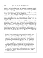
Figure 20-1 shows the basic private VLAN operation. Some host PCs connect to a secondary com-
munity VLAN. The two community VLANs associate with a primary VLAN, where the router con-
nects. The router connects to a promiscuous port on the primary VLAN. A single host PC connects
to a secondary isolated VLAN, so it can communicate only with the router’s promiscuous port.
Figure 20-1 Private VLAN Functionality Within a Switch
Secondary VLAN 10
(Community)
Secondary VLAN 20
(Community)
Secondary VLAN 30
(Isolated)
Host Ports
Primary VLAN
(Promiscuous)
1/1
1/2
1/3
1/4
1/5
2/1
1-58720-077-5.book Page 476 Tuesday, August 19, 2003 3:16 PM
Private VLANs 477
Private VLAN Configuration
Defining a private VLAN involves several configuration steps. These steps are described in the
sections that follow so you can use them.
Configure the Private VLANs
To configure a private VLAN, begin by defining any secondary VLANs that are needed for isolation
using the following configuration commands:
Switch(config)# vv
vv
ll
ll
aa
aa
nn
nn
vlan-id
Switch(config-vlan)# pp
pp
rr
rr
ii
ii
vv
vv
aa
aa
tt
tt
ee
ee
vv
vv
ll
ll
aa
aa
nn
nn
{ii
ii
ss
ss
oo
oo
ll
ll
aa
aa
tt
tt
ee
ee
dd
dd
| cc
cc
oo
oo
mm
mm
mm
mm
uu
uu
nn
nn
ii
ii
tt
tt
yy
yy
}
The secondary VLAN can be an isolated VLAN (no connectivity between isolated ports) or a
community VLAN (connectivity between member ports).
Now, define the primary VLAN that will provide the underlying private VLAN connectivity using
the following configuration commands:
Switch(config)# vv
vv
ll
ll
aa
aa
nn
nn
vlan-id
Switch(config-vlan)# pp
pp
rr
rr
ii
ii
vv
vv
aa
aa
tt
tt
ee
ee
vv
vv
ll
ll
aa
aa
nn
nn
pp
pp
rr
rr
ii
ii
mm
mm
aa
aa
rr
rr
yy
yy
Switch(config-vlan)# pp
pp
rr
rr
ii
ii
vv
vv
aa
aa
tt
tt
ee
ee
vv
vv
ll
ll
aa
aa
nn
nn
aa
aa
ss
ss
ss
ss
oo
oo
cc
cc
ii
ii
aa
aa
tt
tt
ii
ii
oo
oo
nn
nn
{
secondary-vlan-list
| aa
aa
dd
dd
dd
dd
secondary-vlan-
list
| rr
rr
ee
ee
mm
mm
oo
oo
vv
vv
ee
ee
secondary-vlan-list
}
Be sure to associate the primary VLAN with all of its component secondary VLANs using the
association keyword. If the primary VLAN has already been configured, you can add (add) or
remove (remove) secondary VLAN associations individually.
These VLAN configuration commands set up only the mechanisms for unidirectional connectivity
from the secondary VLANs to the primary VLAN. You must also associate the individual switch
ports with their respective private VLANs.
Associate Ports with Private VLANs
First, define the function of the port that will participate on a private VLAN using the following
configuration command:
Switch(config-if)# ss
ss
ww
ww
ii
ii
tt
tt
cc
cc
hh
hh
pp
pp
oo
oo
rr
rr
tt
tt
mm
mm
oo
oo
dd
dd
ee
ee
pp
pp
rr
rr
ii
ii
vv
vv
aa
aa
tt
tt
ee
ee
vv
vv
ll
ll
aa
aa
nn
nn
{hh
hh
oo
oo
ss
ss
tt
tt
| pp
pp
rr
rr
oo
oo
mm
mm
ii
ii
ss
ss
cc
cc
uu
uu
oo
oo
uu
uu
ss
ss
}
If the host connected to this port is a router, firewall, or common gateway for the VLAN, use the
promiscuous keyword. This allows the host to reach all other promiscuous, isolated, or community
ports associated with the primary VLAN. Otherwise, any isolated or community port must receive
the host keyword.
1-58720-077-5.book Page 477 Tuesday, August 19, 2003 3:16 PM
478 Chapter 20: Securing with VLANs
For a nonpromiscuous port (using the switchport mode private-vlan host command), you must
associate the switch port with the appropriate primary and secondary VLANs. Remember, only the
private VLANs themselves have been configured until now. The switch port must know how to
interact with the various VLANs using the following interface configuration command:
Switch(config-if)# ss
ss
ww
ww
ii
ii
tt
tt
cc
cc
hh
hh
pp
pp
oo
oo
rr
rr
tt
tt
pp
pp
rr
rr
ii
ii
vv
vv
aa
aa
tt
tt
ee
ee
vv
vv
ll
ll
aa
aa
nn
nn
hh
hh
oo
oo
ss
ss
tt
tt
aa
aa
ss
ss
ss
ss
oo
oo
cc
cc
ii
ii
aa
aa
tt
tt
ii
ii
oo
oo
nn
nn
primary-vlan-id
secondary-
vlan-id
For a promiscuous port (using the switchport mode private-vlan promiscuous command), you
must map the port to primary and secondary VLANs. Notice that promiscuous mode ports, or ports
that can communicate with any other private VLAN device, are mapped, while other secondary
VLAN ports are associated. One (promiscuous mode port) exhibits bidirectional behavior, while the
other (secondary VLAN ports) exhibits unidirectional or logical behavior.
Use the following interface configuration command to map promiscuous mode ports to primary and
secondary VLANs:
Switch(config-if)# ss
ss
ww
ww
ii
ii
tt
tt
cc
cc
hh
hh
pp
pp
oo
oo
rr
rr
tt
tt
pp
pp
rr
rr
ii
ii
vv
vv
aa
aa
tt
tt
ee
ee
vv
vv
ll
ll
aa
aa
nn
nn
mm
mm
aa
aa
pp
pp
pp
pp
ii
ii
nn
nn
gg
gg
{
primary-vlan-id
} {
secondary-
vlan-list
} | {aa
aa
dd
dd
dd
dd
secondary-vlan-list
} | {rr
rr
ee
ee
mm
mm
oo
oo
vv
vv
ee
ee
secondary-vlan-list
}
As an example, assume the switch in Figure 20-1 is configured as in Example 20-2. Host PCs on
ports FastEthernet 1/1 and 1/2 are in community VLAN 10, hosts on ports FastEthernet 1/4 and 1/5
are in community VLAN 20, and the host on port FastEthernet 1/3 is in isolated VLAN 30. The
router on port FastEthernet 2/1 is in promiscuous mode on primary VLAN 100. Each VLAN is
assigned a role, and the primary VLAN is associated with its secondary VLANs. Then, each
interface is associated with a primary and secondary VLAN (if a host is attached) or mapped to the
primary and secondary VLANs (if a promiscuous host is attached).
NOTE Configuring a static access VLAN on a switch port when the port is associated with
private VLANs is not necessary. Instead, the port takes on membership in the primary and
secondary VLANs simultaneously. This does not mean that the port has a fully functional
assignment to multiple VLANs. Instead, it takes on only the unidirectional behavior between the
secondary and primary VLANs.
Example 20-2 Configuring Ports with Private VLANs
Switch(config)# vv
vv
ll
ll
aa
aa
nn
nn
11
11
00
00
Switch(config-vlan)# pp
pp
rr
rr
ii
ii
vv
vv
aa
aa
tt
tt
ee
ee
vv
vv
ll
ll
aa
aa
nn
nn
cc
cc
oo
oo
mm
mm
mm
mm
uu
uu
nn
nn
ii
ii
tt
tt
yy
yy
Switch(config)# vv
vv
ll
ll
aa
aa
nn
nn
22
22
00
00
Switch(config-vlan)# pp
pp
rr
rr
ii
ii
vv
vv
aa
aa
tt
tt
ee
ee
vv
vv
ll
ll
aa
aa
nn
nn
cc
cc
oo
oo
mm
mm
mm
mm
uu
uu
nn
nn
ii
ii
tt
tt
yy
yy
Switch(config)# vv
vv
ll
ll
aa
aa
nn
nn
33
33
00
00
Switch(config-vlan)# pp
pp
rr
rr
ii
ii
vv
vv
aa
aa
tt
tt
ee
ee
vv
vv
ll
ll
aa
aa
nn
nn
ii
ii
ss
ss
oo
oo
ll
ll
aa
aa
tt
tt
ee
ee
dd
dd
Switch(config)# vv
vv
ll
ll
aa
aa
nn
nn
11
11
00
00
00
00
Switch(config-vlan)# pp
pp
rr
rr
ii
ii
vv
vv
aa
aa
tt
tt
ee
ee
vv
vv
ll
ll
aa
aa
nn
nn
pp
pp
rr
rr
ii
ii
mm
mm
aa
aa
rr
rr
yy
yy
Switch(config-vlan)# pp
pp
rr
rr
ii
ii
vv
vv
aa
aa
tt
tt
ee
ee
vv
vv
ll
ll
aa
aa
nn
nn
aa
aa
ss
ss
ss
ss
oo
oo
cc
cc
ii
ii
aa
aa
tt
tt
ii
ii
oo
oo
nn
nn
11
11
00
00
,,
,,
22
22
00
00
,,
,,
33
33
00
00
1-58720-077-5.book Page 478 Tuesday, August 19, 2003 3:16 PM
Private VLANs 479
Associate Secondary VLANs to a Primary VLAN SVI
On switched virtual interfaces (SVIs), or VLAN interfaces configured with Layer 3 addresses, you
must configure some additional private VLAN mapping. Consider the SVI for the primary VLAN,
VLAN 100, that has an IP address and participates in routing traffic. Secondary VLANs 40 (an
isolated VLAN) and 50 (a community VLAN) are associated at Layer 2 with primary VLAN 100
using the configuration in Example 20-3.
Primary VLAN 200 can forward traffic at Layer 3, but the secondary VLAN associations with it are
only good at Layer 2. To allow Layer 3 traffic switching coming from the secondary VLANs as well,
you must add a private VLAN mapping to the primary VLAN (SVI) interface, using the following
interface configuration command:
Switch(config-if)# pp
pp
rr
rr
ii
ii
vv
vv
aa
aa
tt
tt
ee
ee
vv
vv
ll
ll
aa
aa
nn
nn
mm
mm
aa
aa
pp
pp
pp
pp
ii
ii
nn
nn
gg
gg
{
secondary-vlan-list
| aa
aa
dd
dd
dd
dd
secondary-vlan-list
|
rr
rr
ee
ee
mm
mm
oo
oo
vv
vv
ee
ee
secondary-vlan-list
}
The primary VLAN SVI function is extended to the secondary VLANs, instead of requiring SVIs
for each of them. If some mapping has already been configured for the primary VLAN SVI, you can
add (add) or remove (remove) secondary VLAN mappings individually.
Switch(config-vlan)# ee
ee
xx
xx
ii
ii
tt
tt
Switch(config)# ii
ii
nn
nn
tt
tt
ee
ee
rr
rr
ff
ff
aa
aa
cc
cc
ee
ee
rr
rr
aa
aa
nn
nn
gg
gg
ee
ee
ff
ff
aa
aa
ss
ss
tt
tt
ee
ee
tt
tt
hh
hh
ee
ee
rr
rr
nn
nn
ee
ee
tt
tt
11
11
//
//
11
11
––
––
11
11
//
//
22
22
Switch(config-if)# ss
ss
ww
ww
ii
ii
tt
tt
cc
cc
hh
hh
pp
pp
oo
oo
rr
rr
tt
tt
pp
pp
rr
rr
ii
ii
vv
vv
aa
aa
tt
tt
ee
ee
vv
vv
ll
ll
aa
aa
nn
nn
hh
hh
oo
oo
ss
ss
tt
tt
aa
aa
ss
ss
ss
ss
oo
oo
cc
cc
ii
ii
aa
aa
tt
tt
ii
ii
oo
oo
nn
nn
11
11
00
00
00
00
11
11
00
00
Switch(config)# ii
ii
nn
nn
tt
tt
ee
ee
rr
rr
ff
ff
aa
aa
cc
cc
ee
ee
rr
rr
aa
aa
nn
nn
gg
gg
ee
ee
ff
ff
aa
aa
ss
ss
tt
tt
ee
ee
tt
tt
hh
hh
ee
ee
rr
rr
nn
nn
ee
ee
tt
tt
11
11
//
//
44
44
––
––
11
11
//
//
55
55
Switch(config-if)# ss
ss
ww
ww
ii
ii
tt
tt
cc
cc
hh
hh
pp
pp
oo
oo
rr
rr
tt
tt
pp
pp
rr
rr
ii
ii
vv
vv
aa
aa
tt
tt
ee
ee
vv
vv
ll
ll
aa
aa
nn
nn
hh
hh
oo
oo
ss
ss
tt
tt
aa
aa
ss
ss
ss
ss
oo
oo
cc
cc
ii
ii
aa
aa
tt
tt
ii
ii
oo
oo
nn
nn
11
11
00
00
00
00
22
22
00
00
Switch(config)# ii
ii
nn
nn
tt
tt
ee
ee
rr
rr
ff
ff
aa
aa
cc
cc
ee
ee
ff
ff
aa
aa
ss
ss
tt
tt
ee
ee
tt
tt
hh
hh
ee
ee
rr
rr
nn
nn
ee
ee
tt
tt
11
11
//
//
33
33
Switch(config-if)# ss
ss
ww
ww
ii
ii
tt
tt
cc
cc
hh
hh
pp
pp
oo
oo
rr
rr
tt
tt
pp
pp
rr
rr
ii
ii
vv
vv
aa
aa
tt
tt
ee
ee
vv
vv
ll
ll
aa
aa
nn
nn
hh
hh
oo
oo
ss
ss
tt
tt
aa
aa
ss
ss
ss
ss
oo
oo
cc
cc
ii
ii
aa
aa
tt
tt
ii
ii
oo
oo
nn
nn
11
11
00
00
00
00
33
33
00
00
Switch(config)# ii
ii
nn
nn
tt
tt
ee
ee
rr
rr
ff
ff
aa
aa
cc
cc
ee
ee
ff
ff
aa
aa
ss
ss
tt
tt
ee
ee
tt
tt
hh
hh
ee
ee
rr
rr
nn
nn
ee
ee
tt
tt
22
22
//
//
11
11
Switch(config-if)# ss
ss
ww
ww
ii
ii
tt
tt
cc
cc
hh
hh
pp
pp
oo
oo
rr
rr
tt
tt
mm
mm
oo
oo
dd
dd
ee
ee
pp
pp
rr
rr
ii
ii
vv
vv
aa
aa
tt
tt
ee
ee
vv
vv
ll
ll
aa
aa
nn
nn
pp
pp
rr
rr
oo
oo
mm
mm
ii
ii
ss
ss
cc
cc
uu
uu
oo
oo
uu
uu
ss
ss
Switch(config-if)# ss
ss
ww
ww
ii
ii
tt
tt
cc
cc
hh
hh
pp
pp
oo
oo
rr
rr
tt
tt
pp
pp
rr
rr
ii
ii
vv
vv
aa
aa
tt
tt
ee
ee
vv
vv
ll
ll
aa
aa
nn
nn
mm
mm
aa
aa
pp
pp
pp
pp
ii
ii
nn
nn
gg
gg
11
11
00
00
00
00
11
11
00
00
,,
,,
22
22
00
00
,,
,,
33
33
00
00
Example 20-3 Associating Secondary VLANs to a Primary VLAN
vv
vv
ll
ll
aa
aa
nn
nn
44
44
00
00
pp
pp
rr
rr
ii
ii
vv
vv
aa
aa
tt
tt
ee
ee
vv
vv
ll
ll
aa
aa
nn
nn
ii
ii
ss
ss
oo
oo
ll
ll
aa
aa
tt
tt
ee
ee
dd
dd
vv
vv
ll
ll
aa
aa
nn
nn
55
55
00
00
pp
pp
rr
rr
ii
ii
vv
vv
aa
aa
tt
tt
ee
ee
vv
vv
ll
ll
aa
aa
nn
nn
cc
cc
oo
oo
mm
mm
mm
mm
uu
uu
nn
nn
ii
ii
tt
tt
yy
yy
vv
vv
ll
ll
aa
aa
nn
nn
22
22
00
00
00
00
pp
pp
rr
rr
ii
ii
vv
vv
aa
aa
tt
tt
ee
ee
vv
vv
ll
ll
aa
aa
nn
nn
pp
pp
rr
rr
ii
ii
mm
mm
aa
aa
rr
rr
yy
yy
pp
pp
rr
rr
ii
ii
vv
vv
aa
aa
tt
tt
ee
ee
vv
vv
ll
ll
aa
aa
nn
nn
aa
aa
ss
ss
ss
ss
oo
oo
cc
cc
ii
ii
aa
aa
tt
tt
ii
ii
oo
oo
nn
nn
44
44
00
00
,,
,,
55
55
00
00
ii
ii
nn
nn
tt
tt
ee
ee
rr
rr
ff
ff
aa
aa
cc
cc
ee
ee
vv
vv
ll
ll
aa
aa
nn
nn
22
22
00
00
00
00
ii
ii
pp
pp
aa
aa
dd
dd
dd
dd
rr
rr
ee
ee
ss
ss
ss
ss
11
11
99
99
22
22
11
11
66
66
88
88
11
11
99
99
99
99
11
11
22
22
55
55
55
55
22
22
55
55
55
55
22
22
55
55
55
55
00
00
Example 20-2 Configuring Ports with Private VLANs (Continued)
1-58720-077-5.book Page 479 Tuesday, August 19, 2003 3:16 PM
480 Chapter 20: Securing with VLANs
For the example, you would map the private VLAN with the following command:
ii
ii
nn
nn
tt
tt
ee
ee
rr
rr
ff
ff
aa
aa
cc
cc
ee
ee
vv
vv
ll
ll
aa
aa
nn
nn
22
22
00
00
00
00
pp
pp
rr
rr
ii
ii
vv
vv
aa
aa
tt
tt
ee
ee
vv
vv
ll
ll
aa
aa
nn
nn
mm
mm
aa
aa
pp
pp
pp
pp
ii
ii
nn
nn
gg
gg
44
44
00
00
,,
,,
55
55
00
00
Switch Port Monitoring
Suppose a problem exists on your switched network and you want to use a network analyzer to
gather data. Of interest is a conversation between two hosts connected to the switch, one on interface
FastEthernet 1/1 and the other on FastEthernet 4/7. Both ports are assigned to VLAN 100. If you
connect your analyzer to another port on VLAN 100, what will your packet capture show?
Recall that, by definition, switches learn where MAC addresses are located and forward packets
directly to those ports. The only time a packet is flooded to ports other than the specific destination
is when the destination MAC address has not already been located or when the packet is destined
for a broadcast or multicast address. Therefore, your packet capture shows only the broadcast and
multicast packets that were flooded to the analyzer’s port. None of the interesting conversation will
be overheard.
Catalyst switches can use the Switched Port Analyzer (SPAN) feature to mirror traffic from one
source switch port or VLAN to a destination port. This allows a monitoring device, such as a
network analyzer, to be attached to the destination port for capturing traffic.
When packets arrive on the source port or VLAN, they are specially marked so that they can be
copied to the SPAN destination port as well as the true destination port. In this way, the packet
capture receives an exact copy of the packets that are being forwarded from the source.
SPAN is available in several different forms:
■ Local SPAN—Both the SPAN source and destination are located on the local switch. The
source is one or more switch ports.
■ VLAN-based SPAN (VSPAN)—A variation of local SPAN where the source is a VLAN rather
than a physical port.
■ Remote SPAN (RSPAN)—The SPAN source and destination are located on different switches.
Mirrored traffic is copied over a special-purpose VLAN across trunks between switches from
the source to the destination.
The sections that follow describe each of these SPAN forms in more detail.
1-58720-077-5.book Page 480 Tuesday, August 19, 2003 3:16 PM
Switch Port Monitoring 481
Local SPAN and VSPAN
The SPAN source can be identified as one or more physical switch ports, a trunk, or a VLAN.
Packets that are being forwarded from the destination are also copied into the destination port’s
queue. Because the packets are merely copied, neither the original data nor its being forwarded is
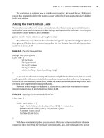
affected. Figure 20-2 demonstrates two cases where a network analyzer on the SPAN destination
port is receiving frames that SPAN has copied from the source port. Here, SPAN session A monitors
all communication on VLAN 100. SPAN session B uses a normal access mode source port to
monitor communication between a server and its client PCs.
Figure 20-2 Basic Local SPAN and VSPAN Operation
What happens if a speed mismatch occurs between the SPAN source and destination ports? This
could easily happen if the source is a VLAN with many hosts, or if the source is a GigabitEthernet
port and the destination is a FastEthernet port.
Packets are copied only into the destination port’s egress queue. If the destination port becomes
congested, the SPAN packets are dropped from the queue and are not seen at the destination port.
Therefore, if the bandwidth of source traffic exceeds the destination port speed, some packets might
not be seen at the destination port. Then, traffic from the SPAN source is not affected by any
congestion at the SPAN destination.
PC
File Server
Network
Analyzer
B
Network
Analyzer
A
A: VSPAN
Source - VLAN 100
B: Source
Port
B: Destination
Port
PCServer
1-58720-077-5.book Page 481 Tuesday, August 19, 2003 3:16 PM
482 Chapter 20: Securing with VLANs
Local SPAN and VSPAN Configuration
You can configure one or more simultaneous SPAN sessions on a Catalyst switch. These sessions
are completely independent because no interaction occurs between the packet mirroring of each.
To configure a SPAN session, start by defining the source of the SPAN session data, using the
following global configuration command:
Switch(config)# mm
mm
oo
oo
nn
nn
ii
ii
tt
tt
oo
oo
rr
rr
ss
ss
ee
ee
ss
ss
ss
ss
ii
ii
oo
oo
nn
nn
session
ss
ss
oo
oo
uu
uu
rr
rr
cc
cc
ee
ee
{ii
ii
nn
nn
tt
tt
ee
ee
rr
rr
ff
ff
aa
aa
cc
cc
ee
ee
type
mod/num
| vv
vv
ll
ll
aa
aa
nn
nn
vlan-id
}
[rr
rr
xx
xx
| tt
tt
xx
xx
| bb
bb
oo
oo
tt
tt
hh
hh
]
SPAN sessions must be uniquely numbered using the session parameter. The maximum number of
supported sessions varies among Catalyst platforms. For example, a Catalyst 3550 can support two
sessions, whereas a Catalyst 6500 can support up to 64. If multiple sources are needed, you can
repeat this command. The SPAN source can be a physical switch interface or a Layer 2 VLAN (not
a logical VLAN interface or SVI).
Traffic can be selected for mirroring based on the direction it is traveling through the SPAN source.
For example, you can select only traffic received on the source (rx), only traffic transmitted from
the source (tx), or traffic in both directions (both). By default, both directions are used.
Next, identify the SPAN destination. You must assign the SPAN source and destination ports to the
same VLAN within the switch; otherwise, the switch cannot copy frames from one VLAN to
another. Use the following global configuration command to identify the SPAN destination:
Switch(config)# mm
mm
oo
oo
nn
nn
ii
ii
tt
tt
oo
oo
rr
rr
ss
ss
ee
ee
ss
ss
ss
ss
ii
ii
oo
oo
nn
nn
session
dd
dd
ee
ee
ss
ss
tt
tt
ii
ii
nn
nn
aa
aa
tt
tt
ii
ii
oo
oo
nn
nn
{{ii
ii
nn
nn
tt
tt
ee
ee
rr
rr
ff
ff
aa
aa
cc
cc
ee
ee
type
mod/num
} | {vv
vv
ll
ll
aa
aa
nn
nn
vlan-id
} | {aa
aa
nn
nn
aa
aa
ll
ll
yy
yy
ss
ss
ii
ii
ss
ss
mm
mm
oo
oo
dd
dd
uu
uu
ll
ll
ee
ee
slot-number
} | {dd
dd
aa
aa
tt
tt
aa
aa
pp
pp
oo
oo
rr
rr
tt
tt
port-number
}}
The session number here must match the one configured for the SPAN source. You can define only
one destination port for each SPAN session. In addition, SPAN sessions cannot share a destination
port. The destination can be a physical interface, a Layer 2 VLAN (not a VLAN SVI interface), or
a Network Analysis Module (NAM, Catalyst 6500 only).
You can narrow down the data copied over from the source, if necessary. If the source is a trunk port,
you can mirror only traffic from specific VLANs on the trunk with the following global
configuration command:
Switch(config)# mm
mm
oo
oo
nn
nn
ii
ii
tt
tt
oo
oo
rr
rr
ss
ss
ee
ee
ss
ss
ss
ss
ii
ii
oo
oo
nn
nn
session-number
ff
ff
ii
ii
ll
ll
tt
tt
ee
ee
rr
rr
vv
vv
ll
ll
aa
aa
nn
nn
vlan-range
Also, if using a VACL, you can identify and mark interesting traffic for SPAN capture. In this case,
use the capture keyword in the VACL action statement.
1-58720-077-5.book Page 482 Tuesday, August 19, 2003 3:16 PM
Switch Port Monitoring 483
You can delete a SPAN session after the packet analysis is complete. SPAN sessions are numbered,
so you can delete them by referencing the number. Use the following global configuration command
to delete one or more sessions:
Switch(config)# nn
nn
oo
oo
mm
mm
oo
oo
nn
nn
ii
ii
tt
tt
oo
oo
rr
rr
ss
ss
ee
ee
ss
ss
ss
ss
ii
ii
oo
oo
nn
nn
{{rr
rr
aa
aa
nn
nn
gg
gg
ee
ee
session-range
} | ll
ll
oo
oo
cc
cc
aa
aa
ll
ll
| aa
aa
ll
ll
ll
ll
|
session
}
Session numbers can be given as an individual session, a range of sessions, all local SPAN sessions,
or all sessions (local or remote). To see the list of currently active SPAN sessions, use the show
monitor EXEC command, as shown in Example 20-4. Here, two SPAN sessions are in use on a
Catalyst 3550.
Example 20-4 Displaying the Currently Active SPAN Sessions
Switch# ss
ss
hh
hh
oo
oo
ww
ww
mm
mm
oo
oo
nn
nn
ii
ii
tt
tt
oo
oo
rr
rr
Session 1
Type : Local Session
Source Ports:
RX Only: None
TX Only: None
Both: Fa0/7
Source VLANs:
RX Only: None
TX Only: None
Both: None
Source RSPAN VLAN: None
Destination Ports: Fa0/47
Encapsulation: Native
Ingress: Disabled
Reflector Port: None
Filter VLANs: None
Dest RSPAN VLAN: None
Session 2
Type : Local Session
Source Ports:
RX Only: None
TX Only: None
Both: Gi0/1
Source VLANs:
RX Only: None
TX Only: None
Both: None
continues
1-58720-077-5.book Page 483 Tuesday, August 19, 2003 3:16 PM
484 Chapter 20: Securing with VLANs
Remote SPAN
In a large switched network or one that is geographically separated, it might not always be conve-
nient to take a network analysis to the switch where a SPAN source is located. To make SPAN more
extensible, Cisco developed the Remote SPAN (RSPAN) feature. With RSPAN, the source and
destination can be located on different switches in different locations.
The RSPAN source is identified on one switch, just as with local SPAN. The RSPAN destination is
identified on its local switch. Then, RSPAN can carry only the mirrored data over a special-purpose
VLAN across trunk links and intermediate switches. As long as every switch along the way is
RSPAN-capable, the source can be located at the far-end switch, while the network analyzer is
conveniently located at the switch nearest you.
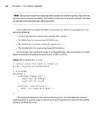
Figure 20-3 shows an example network using RSPAN where the packets from the file server (source
port) on one switch are copied and transported over the RSPAN VLAN on trunk links. At the
destination switch, packets are pulled off the RSPAN VLAN and copied to the network analyzer
(destination port). The file server and network analyzer are stationed in geographically separate
locations.
Source RSPAN VLAN: None
Destination Ports: Gi0/2
Encapsulation: Native
Ingress: Disabled
Reflector Port: None
Filter VLANs: None
Dest RSPAN VLAN: None
CAUTION After you finish using a SPAN session, you should always disable or delete it.
Otherwise, someone might try to connect to the port that is configured as the SPAN destination
at some later date. You could spend a good bit of time troubleshooting that user’s connectivity
problem only to find that you left a SPAN session active!
NOTE When Local SPAN or VSPAN is enabled, the Spanning Tree Protocol (STP) is disabled
on the destination port. This allows STP BPDUs to be captured and monitored but also allows the
possibility for a bridging loop to form. Never connect a SPAN session’s destination port back into
an active network. If the monitored packets need to be sent toward another switch, use RSPAN
instead.
Example 20-4 Displaying the Currently Active SPAN Sessions (Continued)
1-58720-077-5.book Page 484 Tuesday, August 19, 2003 3:16 PM
Switch Port Monitoring 485
Figure 20-3 Example of Remote SPAN Operation
The RSPAN VLAN has some important differences from a regular VLAN. First, MAC address
learning is disabled on the RSPAN VLAN. This is to prevent intermediate switches that transport
the RSPAN VLAN from trying to forward the mirrored packets to their real destination MAC
addresses. After all, the purpose of SPAN or RSPAN is to simply mirror or copy interesting
frames—not forward them normally.
An RSPAN-capable switch also floods the RSPAN packets out all of its ports belonging to the
RSPAN VLAN in an effort to send them toward the RSPAN destination. Intermediate switches have
no knowledge of the RSPAN source or destination; rather, they know only of the RSPAN VLAN
itself.
Remote SPAN Configuration
RSPAN configuration begins with the definition of the special-purpose RSPAN VLAN. If you
configure the RSPAN VLAN on a VTP server, VTP correctly propagates it to other intermediate
switches. If not using VTP, be sure to configure this VLAN for RSPAN explicitly on each
intermediate switch. Otherwise, the RSPAN packets will not be delivered correctly.
Trunk Trunk
Trunk
Network
Analyzer
Source
Port
Destination
Port
RSPAN
1-58720-077-5.book Page 485 Tuesday, August 19, 2003 3:16 PM
486 Chapter 20: Securing with VLANs
In addition, if VTP pruning is in use, the RSPAN VLAN will be pruned from unnecessary trunks,
limiting the traffic impact in unrelated areas of the network.
Create and maintain one or more RSPAN VLANs for the special monitoring purpose only. Set aside
one RSPAN VLAN for each RSPAN session that will be used. Don’t allow any normal hosts to join
an RSPAN VLAN. Define an RSPAN VLAN on each switch between the source and destination
with the following configuration commands:
Switch(config)# vv
vv
ll
ll
aa
aa
nn
nn
vlan-id
Switch(config-vlan)# rr
rr
ee
ee
mm
mm
oo
oo
tt
tt
ee
ee
ss
ss
pp
pp
aa
aa
nn
nn
Next, you must identify the RSPAN source and destination on the two switches where the source
and destination are connected. At the source switch, identify the source and destination with the
following global configuration commands:
Switch(config)# mm
mm
oo
oo
nn
nn
ii
ii
tt
tt
oo
oo
rr
rr
ss
ss
ee
ee
ss
ss
ss
ss
ii
ii
oo
oo
nn
nn
session
ss
ss
oo
oo
uu
uu
rr
rr
cc
cc
ee
ee
{ii
ii
nn
nn
tt
tt
ee
ee
rr
rr
ff
ff
aa
aa
cc
cc
ee
ee
type
mod/num
| vv
vv
ll
ll
aa
aa
nn
nn
vlan-id
}
[rr
rr
xx
xx
| tt
tt
xx
xx
| bb
bb
oo
oo
tt
tt
hh
hh
]
Switch(config)# mm
mm
oo
oo
nn
nn
ii
ii
tt
tt
oo
oo
rr
rr
ss
ss
ee
ee
ss
ss
ss
ss
ii
ii
oo
oo
nn
nn
session
dd
dd
ee
ee
ss
ss
tt
tt
ii
ii
nn
nn
aa
aa
tt
tt
ii
ii
oo
oo
nn
nn
rr
rr
ee
ee
mm
mm
oo
oo
tt
tt
ee
ee
vv
vv
ll
ll
aa
aa
nn
nn
rspan-vlan-id
Here, the source is either a physical switch interface or a Layer 2 VLAN (not a VLAN SVI
interface). Notice that the command syntax is identical to the Local SPAN source command. The
RSPAN destination is simply the RSPAN VLAN. This allows the mirrored packets to be copied into
the special VLAN and sent on their way toward the final RSPAN destination.
At the destination switch, you must again identify the RSPAN source and destination by using the
following global configuration commands:
Switch(config)# mm
mm
oo
oo
nn
nn
ii
ii
tt
tt
oo
oo
rr
rr
ss
ss
ee
ee
ss
ss
ss
ss
ii
ii
oo
oo
nn
nn
session
ss
ss
oo
oo
uu
uu
rr
rr
cc
cc
ee
ee
rr
rr
ee
ee
mm
mm
oo
oo
tt
tt
ee
ee
vv
vv
ll
ll
aa
aa
nn
nn
rspan-vlan-id
Switch(config)# mm
mm
oo
oo
nn
nn
ii
ii
tt
tt
oo
oo
rr
rr
ss
ss
ee
ee
ss
ss
ss
ss
ii
ii
oo
oo
nn
nn
session
dd
dd
ee
ee
ss
ss
tt
tt
ii
ii
nn
nn
aa
aa
tt
tt
ii
ii
oo
oo
nn
nn
{ii
ii
nn
nn
tt
tt
ee
ee
rr
rr
ff
ff
aa
aa
cc
cc
ee
ee
type
| vv
vv
ll
ll
aa
aa
nn
nn
vlan-id
}
Here, the roles are reversed. RSPAN packets are pulled from the RSPAN VLAN and placed onto the
destination, which is either a physical switch interface or a Layer 2 VLAN.
NOTE Be aware that RSPAN traffic can increase the traffic load on a trunk, even though RSPAN
is restricted to one special VLAN within the trunk. If the additional load is significant, the normal
production and the monitored traffic contend with each other for available bandwidth. As a result,
both types of traffic could suffer.
Also, RSPAN must allow the STP to run on the RSPAN VLAN to prevent bridging loops from
forming. As a result, STP BPDUs are normally sent and received on the VLAN. You cannot
monitor BPDUs with RSPAN.
1-58720-077-5.book Page 486 Tuesday, August 19, 2003 3:16 PM
Switch Port Monitoring 487
In Example 20-5, RSPAN is configured on all three switches shown in Figure 20-3. The source is
connected to Catalyst A port FastEthernet 1/1. The destination is a network analyzer connected to
port FastEthernet 4/48 on Catalyst C. Catayst B simply passes the RSPAN session traffic over
VLAN 999, transported by trunk links.
Example 20-5 Configuring RSPAN on the Catalyst Switches in Figure 20-3
Catalyst A
vv
vv
ll
ll
aa
aa
nn
nn
99
99
99
99
99
99
rr
rr
ee
ee
mm
mm
oo
oo
tt
tt
ee
ee
ss
ss
pp
pp
aa
aa
nn
nn
mm
mm
oo
oo
nn
nn
ii
ii
tt
tt
oo
oo
rr
rr
ss
ss
ee
ee
ss
ss
ss
ss
ii
ii
oo
oo
nn
nn
11
11
ss
ss
oo
oo
uu
uu
rr
rr
cc
cc
ee
ee
ii
ii
nn
nn
tt
tt
ee
ee
rr
rr
ff
ff
aa
aa
cc
cc
ee
ee
ff
ff
aa
aa
ss
ss
tt
tt
ee
ee
tt
tt
hh
hh
ee
ee
rr
rr
nn
nn
ee
ee
tt
tt
11
11
//
//
11
11
bb
bb
oo
oo
tt
tt
hh
hh
mm
mm
oo
oo
nn
nn
ii
ii
tt
tt
oo
oo
rr
rr
ss
ss
ee
ee
ss
ss
ss
ss
ii
ii
oo
oo
nn
nn
11
11
dd
dd
ee
ee
ss
ss
tt
tt
ii
ii
nn
nn
aa
aa
tt
tt
ii
ii
oo
oo
nn
nn
rr
rr
ee
ee
mm
mm
oo
oo
tt
tt
ee
ee
vv
vv
ll
ll
aa
aa
nn
nn
99
99
99
99
99
99
Catalyst B
vv
vv
ll
ll
aa
aa
nn
nn
99
99
99
99
99
99
rr
rr
ee
ee
mm
mm
oo
oo
tt
tt
ee
ee
ss
ss
pp
pp
aa
aa
nn
nn
Catalyst C
vv
vv
ll
ll
aa
aa
nn
nn
99
99
99
99
99
99
rr
rr
ee
ee
mm
mm
oo
oo
tt
tt
ee
ee
ss
ss
pp
pp
aa
aa
nn
nn
mm
mm
oo
oo
nn
nn
ii
ii
tt
tt
oo
oo
rr
rr
ss
ss
ee
ee
ss
ss
ss
ss
ii
ii
oo
oo
nn
nn
11
11
ss
ss
oo
oo
uu
uu
rr
rr
cc
cc
ee
ee
rr
rr
ee
ee
mm
mm
oo
oo
tt
tt
ee
ee
vv
vv
ll
ll
aa
aa
nn
nn
99
99
99
99
99
99
mm
mm
oo
oo
nn
nn
ii
ii
tt
tt
oo
oo
rr
rr
ss
ss
ee
ee
ss
ss
ss
ss
ii
ii
oo
oo
nn
nn
11
11
dd
dd
ee
ee
ss
ss
tt
tt
ii
ii
nn
nn
aa
aa
tt
tt
ii
ii
oo
oo
nn
nn
ii
ii
nn
nn
tt
tt
ee
ee
rr
rr
ff
ff
aa
aa
cc
cc
ee
ee
ff
ff
aa
aa
ss
ss
tt
tt
ee
ee
tt
tt
hh
hh
ee
ee
rr
rr
nn
nn
ee
ee
tt
tt
44
44
//
//
44
44
88
88
1-58720-077-5.book Page 487 Tuesday, August 19, 2003 3:16 PM
488 Chapter 20: Securing with VLANs
Foundation Summary
The Foundation Summary is a collection of information that provides a convenient review of many
key concepts in this chapter. If you are already comfortable with the topics in this chapter, this
summary can help you recall a few details. If you just read this chapter, this review should help
solidify some key facts. If you are doing your final preparation before the exam, this information
will hopefully be a convenient way to review the day before the exam.
■ VLAN Access Lists (VACLs) can control packets that are bridged, switched, or routed. VACLs
are effective on packets that stay within a single VLAN.
■ Private VLANs provide special unidirectional relationships between entities on a single VLAN.
■ Private VLANs are implemented as primary and secondary VLANs.
■ Primary VLANs allow hosts to communicate with any other type of private (secondary) VLAN.
■ Secondary VLANs allow hosts to communicate with ports on a primary VLAN but not with
other secondary VLANs.
■ Secondary VLANs are categorized as follows:
— Isolated VLAN—Hosts can communicate only with the primary VLAN not any other
isolated port or secondary VLAN.
— Community VLAN—Hosts can communicate with the primary VLAN and other hosts in
the community VLAN but not with any other isolated or community VLAN.
■ Secondary VLANs must be associated with one primary VLAN.
Table 20-2 VLAN ACL Configuration Commands
Task Command Syntax
Define a VACL. vlan access-map map-name [sequence-number]
Define a matching
condition.
match {ip address {acl-number | acl-name}} | {ipx address {acl-
number | acl-name} | {mac address acl-name}}
Define an action. action {drop | forward [capture] | redirect interface type mod/num}
Apply the VACL to
VLANs.
vlan filter map-name vlan-list vlan-list
1-58720-077-5.book Page 488 Tuesday, August 19, 2003 3:16 PM
Foundation Summary 489
■ You can configure switch ports using private VLANs as follows:
— Promiscuous—Usually connects to a router, firewall, or gateway device; this type of port
can communicate with any other type of private VLAN.
— Host—Usually connects to regular hosts; this type of port can communicate with a
promiscuous port or ports on the same community VLAN.
■ Switch port monitoring can monitor or capture interesting traffic on a Catalyst switch.
■ Local SPAN copies frames from a source to a destination port on the local switch.
■ VLAN SPAN (VSPAN) copies frames from a source VLAN to a destination port on the local
switch.
■ Remote SPAN (RSPAN) copies frames from a source on one switch to a destination on another
switch. Frames are carried over a special RSPAN VLAN across intermediate switches and
trunks.
Table 20-3 Private VLAN Configuration Commands
Task Command Syntax
Define a secondary
VLAN.
vlan vlan-id
private-vlan {isolated | community}
Define a primary VLAN;
associate it with
secondary VLANs.
vlan vlan-id
private-vlan primary
private-vlan association {secondary-vlan-list | add secondary-vlan-list
| remove secondary-vlan-list}
Associate ports with
private VLANs.
switchport mode private-vlan {host | promiscuous}
Associate nonpromiscu-
ous ports with private
VLANs.
switchport private-vlan host-association primary-vlan-id secondary-
vlan-id
Associate promiscuous
ports with private
VLANs.
switchport private-vlan mapping {primary-vlan-id} {secondary-vlan-
list} | {add secondary-vlan-list} | {remove secondary-vlan-list}
Associate secondary
VLANs with a Primary
VLAN Layer 3 SVI.
private-vlan mapping {secondary-vlan-list | add secondary-vlan-list |
remove secondary-vlan-list}
1-58720-077-5.book Page 489 Tuesday, August 19, 2003 3:16 PM
490 Chapter 20: Securing with VLANs
Table 20-4 Local or VLAN SPAN Commands
Task Command Syntax
Identify a SPAN session
source.
monitor session session source {interface type | vlan vlan-id} [rx | tx | both]
Identify a SPAN session
destination.
monitor session session destination {{interface type mod/num} | {vlan
vlan-id} | {analysis-module slot-number} | {data-port port-number}}
Filter VLANs from a
SPAN source trunk.
monitor session session-number filter vlan vlan-range
Remove a SPAN session. no monitor session {{range session-range} | local | all | session}
Table 20-5 RSPAN Commands
Task Command Syntax
Define an RSPAN VLAN for
transport (all switches from source
to destination).
vlan vlan-id
remote-span
Source switch: identify the
RSPAN source and destination.
monitor session session source {interface type mod/num | vlan
vlan-id} [rx | tx | both]
monitor session session destination remote vlan rspan-vlan-id
Destination switch: identify the
RSPAN source and destination.
monitor session session source remote vlan rspan-vlan-id
monitor session session destination {interface type mod/num |
vlan vlan-id}
1-58720-077-5.book Page 490 Tuesday, August 19, 2003 3:16 PM
Q&A
The questions and scenarios in this book are more difficult than what you should experience on the
actual exam. The questions do not attempt to cover more breadth or depth than the exam; however,
they are designed to make sure that you know the answers. Rather than allowing you to derive the
answers from clues hidden inside the questions themselves, the questions challenge your under-
standing and recall of the subject. Hopefully, these questions will help limit the number of exam
questions on which you narrow your choices to two options and then guess.
You can find the answers to these questions in Appendix A.
1. When a VACL is implemented on a switch, how is the switching speed affected?
2. What actions can be taken on packets matching a VACL?
3. After a VACL is applied using the vlan filter command, how is the traffic direction (inbound or
outbound) specified?
4. A secondary community VLAN is associated with a primary VLAN on a switch. Can hosts
assigned to the community VLAN communicate with each other?
5. A secondary isolated VLAN is associated with a primary VLAN on a switch. Can hosts
assigned to the isolated VLAN communicate with each other?
6. What command is needed to configure a promiscuous VLAN?
7. A router is identifed as the central gatewawy for a private VLAN. What command is needed to
configure the switch port where a router is connected?
8. How many actual VLANs must be configured to implement a common router with two
community VLANs?
9. How is switching performance affected when several SPAN sessions are enabled?
10. What command can specify the source of a SPAN session as VLAN 100?
11. When a SPAN session is enabled, what direction of traffic flow (relative to the source port) is
mirrored for analysis?
1-58720-077-5.book Page 491 Tuesday, August 19, 2003 3:16 PM
492 Chapter 20: Securing with VLANs
12.
What two things can identify more granular traffic to be mirrored to a SPAN destination?
13. Three switches are connected in series with trunk links. The RSPAN source is on the first switch
and the destination is on the third. How does the intermediate (second) switch learn about the
RSPAN’s source and destination locations?
14. What must be configured on all switches connecting an RSPAN source and destination? What
commands can be used?
15. One of the advantages of RSPAN is that mirrored traffic can be isolated in the RSPAN VLAN
on a trunk. If a GigabitEthernet port is to be monitored on one switch, which is better to use as
a transport for the RSPAN VLAN: a GigabitEthernet trunk already carrying user traffic in other
VLANs, or an isolated GigabitEthernet trunk link set aside for RSPAN?
1-58720-077-5.book Page 492 Tuesday, August 19, 2003 3:16 PM
1-58720-077-5.book Page 493 Tuesday, August 19, 2003 3:16 PM
PART V: Scenarios for Final
Preparation
Chapter 21 Scenarios for Final Preparation
1-58720-077-5.book Page 494 Tuesday, August 19, 2003 3:16 PM
The chapter in this part of the book emphasizes an overall understanding of switching concepts,
configuration commands, and network operation. Although the CCNP BCMSN exam might not
contain scenarios of this type, you can better prepare by thinking about the “bigger picture” of
a network and how you can apply each switching topic.
1-58720-077-5.book Page 495 Tuesday, August 19, 2003 3:16 PM