Electrical Power Systems Quality, Second Edition phần 9 potx
Bạn đang xem bản rút gọn của tài liệu. Xem và tải ngay bản đầy đủ của tài liệu tại đây (333.69 KB, 53 trang )
capability to electromechanical network relays. In the past, these sup-
plemental relays had minimum time delays of 1 s or more since their
mission was to wait for the elevator to descend. However, not all util-
ities endorse this low-current, time-delay technique. Some feel that
any time delay in opening the network protectors degrades the high
service quality that the network system is intended to provide.
The load-generation control and DG tripping schemes mentioned
above are intended to ensure that the network protectors are never
opened by exported power. As long as the schemes work properly, the
network protectors are never exposed to the out-of-phase voltage con-
ditions that may exceed the switch capability. However, because of the
potentially catastrophic consequences of causing a network protector
failure, it is prudent to provide a backup. An interlocking scheme that
trips the DG instantaneously when a certain number of network pro-
tectors have opened ensures that the network protectors will not be
exposed to out-of-phase voltages for more than a few cycles. The deci-
sion as to how many protectors must open before the DG is tripped
(one, two, or all) is a tradeoff between security of the protectors and
nuisance tripping of the DG. Note that this scheme does not relieve the
DG installer from the responsibility of providing stuck-breaker backup
protection for the DG’s switching device.
An even more secure approach to avoiding overstressing the network
protectors is to replace existing protectors with new designs that are
capable of interrupting fault currents from sources with higher X/R
422 Chapter Nine
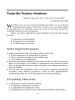
Time
Adjustable
delay time
Time delay for
low currents
Adjustable
instantaneous trip
threshold
Instantaneous trip
for higher currents
100
Current (% of transformer rating)
Figure 9.32 Adjustable reverse-power characteristic.
Distributed Generation and Power Quality
Downloaded from Digital Engineering Library @ McGraw-Hill (www.digitalengineeringlibrary.com)
Copyright © 2004 The McGraw-Hill Companies. All rights reserved.
Any use is subject to the Terms of Use as given at the website.
ratios and of withstanding out-of-phase voltages across the open
switch. One major U.S. manufacturer of network protector units has
recently introduced such high-capacity protectors in 800- to 2250-A rat-
ings and plans to introduce them in ratings up to 6000 A. These pro-
tectors are designed to be retrofitted in many existing types of network
units.
A possible DG interconnection problem exists that would involve net-
work protectors without a network bus interconnection. If a DG is
interconnected on a feeder that also supplies a network unit, then if its
feeder breaker is tripped and the DG is not rapidly isolated, it may
impact one or more of the network units as if it were isolated on the net-
work bus. For this type of event to occur, the DG output does not have
to be matched to the feeder load. For the excess generation case, it only
has to be momentarily greater than the load on the network bus. Under
this condition the power continues to flow to the network bus from the
feeder with the interconnected DG, which keeps that protector closed.
However, the excess power flows through the network back to the other
feeders, resulting in the opening of the protectors connected to those
feeders. Once open, these protectors will be separating two indepen-
dent systems. For the case of less generation than load, the protector
connecting to the feeder with the generation may trip. Again, such a
condition would have a protector separating two independent systems.
Therefore, such DG applications should be avoided unless the DG
breaker is interlocked with the feeder breaker with a direct transfer
trip scheme.
9.7 Siting DG
The value of DG to the power delivery system is very much dependent
on time and location. It must be available when needed and must be
where it is needed. This is an often neglected or misunderstood concept
in discussions about DG. Many publications on DG assume that if 1
MW of DG is added to the system, 1 MW of additional load can be
served. This is not always true.
Utility distribution engineers generally feel more comfortable with
DG installed on facilities they maintain and control. The obvious choice
for a location is a substation where there is sufficient space and com-
munications to control centers. This is an appropriate location if the
needs are capacity relief on the transmission system or the substation
transformer. It is also adequate for basic power supply issues, and one
will find many peaking units in substations. However, to provide sup-
port for distribution feeders, the DG must be sited out on the feeder
away from the substation. Such generation will also relieve capacity
constraints on transmission and power supply. In fact, it is more effec-
Distributed Generation and Power Quality 423
Distributed Generation and Power Quality
Downloaded from Digital Engineering Library @ McGraw-Hill (www.digitalengineeringlibrary.com)
Copyright © 2004 The McGraw-Hill Companies. All rights reserved.
Any use is subject to the Terms of Use as given at the website.
tive than the same amount of DG installed in the substation.
Unfortunately, this generation is usually customer-owned and distrib-
ution planners are reluctant to rely on it for capacity.
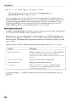
The application of DG to relieve feeder capacity constraints is illus-
trated in Fig. 9.33. The feeder load has grown to where it exceeds a
limit on the feeder. This limit could be imposed by either current rat-
ings on lines or switchgear. It could also be imposed by bus voltage lim-
its. There is DG on the feeder at a location where it can actually relieve
the constraint and is dispatched near the daily peak to help serve the
load. The straightforward message of the figure is that the load that
would otherwise have to be curtailed can now be served. Therefore, the
reliability has been improved.
This application is becoming more common as a means to defer
expansion of the wire-based power delivery infrastructure. The gener-
ation might be leased for a peak load period. However, it is more com-
mon to offer capacity credits to customers located in appropriate areas
to use their backup generation for the benefit of the utility system. If
there are no customers with DG in the area, utilities may lease space
to connect generation or, depending on regulatory rules, may provide
some incentives for customers to add backup generation.
There is by no means universal agreement that this is a permanent
solution to the reliability problem. When utility planners are shown
Fig. 9.33, most will concede the obvious, but not necessarily agree that
this situation represents an improvement in reliability. Three of the
stronger arguments are
1. If the feeder goes out, only the customer with the DG sees an
improvement in reliability. There is no noticeable change in the ser-
vice reliability indices.
424 Chapter Nine
Feeder Limit
DG Dispatched
ON
Daily Load Profile
DG Sited to Provide Feeder Relief
Figure 9.33 DG sited to relieve feeder overload constraint.
Distributed Generation and Power Quality
Downloaded from Digital Engineering Library @ McGraw-Hill (www.digitalengineeringlibrary.com)
Copyright © 2004 The McGraw-Hill Companies. All rights reserved.
Any use is subject to the Terms of Use as given at the website.
2. Customer generation cannot be relied upon to start when needed.
Thus, the reliability cannot be expected to improve.
3. Using customer-owned generation in this fashion masks the true
load growth. Investment in wire facilities lags behind demand,
increasing the risk that the distribution system will eventually not
be able to serve the load.
It should also be noted that the capacity relief benefit is nullified
when the distribution system is upgraded and no longer has a con-
straint. Thus, capacity credits offered for this application generally
have a short term ranging from 6 months to 1 year.
If one had to choose a location on the distribution feeder, where
should the DG be located? The optimal DG siting problem is similar to
the optimal siting problem for shunt capacitor banks. Many of the same
algorithms can be used with the chief difference being that the object
being added produces watts in addition to vars. Some of the same rules
of thumb also apply. For example, if the load is uniformly distributed
along the feeder, the optimal point for loss reduction and capacity relief
is approximately two-thirds of the way down the main feeder. When
there are more generators to consider, the problem requires computer
programs for analysis.
The utility does not generally have a choice in the location of feeder-
connected DG. The location is given for customer-owned generation,
and the problem is to determine if the location has any capacity-related
value to the power delivery system. Optimal siting algorithms can be
employed to evaluate the relative value of alternative sites.
One measure of the value of DG in a location is the additional
amount of load that can be served relative to the size of the DG.
Transmission networks are very complex systems that are sometimes
constrained by one small area that affects a large geographical area. A
relatively small amount of load reduction in the constrained area
allows several times that amount of load to be served by the system.
This effect can also be seen on distribution feeders. Because of the
simple, radial structure of most feeders, there is generally not a con-
straint so severe that DG application will allow the serving of addi-
tional load several times greater than the size of the generator.
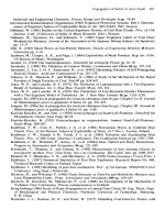
However, there can be a multiplying effect as illustrated in Fig. 9.34.
This example assumes that the constraint is on the feeder rather
than on the substation. If 1 MW of generation were placed in the sub-
station, no additional load could be served on the feeder because no
feeder relief has been achieved. However, if there is a good site on the
feeder, the total feeder load often can grow by as much as 1.4 MW. This
is a typical maximum value for this measure of DG benefit on radial
distribution feeders.
Distributed Generation and Power Quality 425
Distributed Generation and Power Quality
Downloaded from Digital Engineering Library @ McGraw-Hill (www.digitalengineeringlibrary.com)
Copyright © 2004 The McGraw-Hill Companies. All rights reserved.
Any use is subject to the Terms of Use as given at the website.
Another application that is becoming common is the use of DG to
cover contingencies. Traditionally, utilities have built sufficient wire-
based delivery capacity to serve the peak load assuming one major fail-
ure (the so-called N-1 contingency design criterion). At the distribution
feeder level, this involves adding sufficient ties to other feeders so that
the load can be conveniently switched to an alternate feeder when a
failure occurs. There must also be sufficient substation capacity to
serve the normal load and the additional load expected to be switched
over during a failure. This results in substantial overcapacity when the
system is in its normal state with no failures.
One potentially good economic application of DG is to provide sup-
port for feeders when it is necessary to switch them to an alternate
source while repairs are made. Figure 9.35 depicts the use of DG
located on the feeder for this purpose. This will be substantially less
costly than building a new feeder or upgrading a substation to cover
this contingency.
The DG in this case is located near the tie-point between two feeders.
It is not necessarily used for feeder support during normal conditions
although there would often be some benefits to be gained by operating
the DG at peak load. When a failure occurs on either side of the tie, the
open tie switch is closed to pick up load from the opposite side. The DG
is dispatched on and connected to help support the backup feeder.
Locating the DG in this manner gives the utility additional flexibil-
ity and more reconfiguration options. Currently, the most common DG
technology used for this application is currently diesel gensets. The
gensets may be mounted on portable trailers and leased only for the
peak load season when a particular contingency leaves the system vul-
nerable. One or more units may be interconnected through a pad-
426 Chapter Nine
⌬P
load
⌬P
gen
= 0
⌬P
load
⌬P
gen
= 1.4
Figure 9.34 Ability of DG to increase the capacity of a distribution feeder is
dependent on DG location.
Distributed Generation and Power Quality
Downloaded from Digital Engineering Library @ McGraw-Hill (www.digitalengineeringlibrary.com)
Copyright © 2004 The McGraw-Hill Companies. All rights reserved.
Any use is subject to the Terms of Use as given at the website.
mounted transformer and may also employ a recloser with a DG pro-
tection relay. This makes a compact and safe interconnection package
using equipment familiar to utility personnel.
9.8 Interconnection Standards
Standards for interconnection of DG to distribution systems are exam-
ined in this section. Two examples illustrating the range of require-
ments for interconnection protection are presented.
9.8.1 Industry standards efforts
There have been two main DG interconnection standards efforts in the
United States. IEEE Standard 929-2000
5
was developed to address
requirements for inverters used in photovoltaic systems interconnected
with utility systems. The standard has been generally applied to all
technologies requiring an inverter interface. One of the main issues
this standard addresses is the anti-islanding scheme. The basic idea is
to introduce a destabilizing signal into the switching control so that it
will quickly drift in frequency if allowed to run isolated while the con-
trol thinks it is still interconnected. Amid fears that vendors would
independently choose schemes that might cancel out each other, agree-
ment was reached on a uniform direction to drive the frequency.
Another, more contested effort has been the development of IEEE
Standard P1547,
10
which has not been approved as of the time of this
writing. The intent is to develop a national standard that will apply to
the interconnection of all types of DG to both the radial and network dis-
tribution systems. Vendors, utilities, and end users have joined in this
effort, which appears to be converging. This draft standard addresses
many of the issues described in this chapter, and the approach taken
here is largely consistent with the contents of this document.
9.8.2 Interconnection requirements
The basic requirements for interconnecting DG to the utility distribu-
tion system are listed here.
Distributed Generation and Power Quality 427
Figure 9.35 DG sited near the tie-point between two feeders to help support
contingencies.
Distributed Generation and Power Quality
Downloaded from Digital Engineering Library @ McGraw-Hill (www.digitalengineeringlibrary.com)
Copyright © 2004 The McGraw-Hill Companies. All rights reserved.
Any use is subject to the Terms of Use as given at the website.
Voltage regulation. DG shall not attempt to regulate voltage while
interconnected unless special agreement is reached with the utility. As
pointed out previously, this generally means that the DG will operate
at a constant power factor or constant reactive power output acceptable
to the operation of the system. Inverters in utility-interactive mode
would typically operate by producing a current in phase with the volt-
age to achieve a particular power output level.
Anti-islanding. DG shall have relaying that is capable of detecting
when it is operating as an island and disconnect from the power sys-
tem. Inverters should be compliant with IEEE Standard 929-2000 such
that they would naturally drift in frequency when isolated from the
utility source. Relaying to detect resonant conditions that might occur
should be applied in susceptible DG applications.
Fault detection. DG shall have relaying capable of detecting faults on
the utility system and disconnecting after a time delay of typically 0.16
to 2.0 s, depending on the amount of deviation from normal. DG should
disconnect sufficiently early in the first reclose interval to allow tem-
porary faults to clear. (The utility may have to extend the first reclose
interval to ensure that this can be accomplished.) However, to prevent
nuisance tripping of the DG, the tripping should not be too fast. The
0.16-s (10 cycles at 60 Hz) delay is to allow time for faults on the trans-
mission system or adjacent feeder to clear before tripping the DG need-
lessly.
Settings proposed for voltage and frequency relays for this applica-
tion are given in Table 9.1.
10
The cutoff voltages are nominal guidelines
and may have to be modified for some applications. A common adjust-
ment is to decrease the voltage trip levels to avoid nuisance tripping for
faults on parallel feeders. For example, faults on parallel feeders will
sometimes give voltages less than 50 percent, requiring the setting on
428 Chapter Nine
TABLE 9.1 Typical Voltage and
Frequency Relay Settings for DG
Interconnection for a 60-Hz System
Condition Clearing time, s
V Յ 50% 0.16
50% Ͻ V Յ 88% 2.0
110% Ͻ V Յ 120% 1.0
V Ͼ 120% 0.16
f Ͻ 59.3 Hz 0.16
f Ͼ 60.5 Hz 0.16
Distributed Generation and Power Quality
Downloaded from Digital Engineering Library @ McGraw-Hill (www.digitalengineeringlibrary.com)
Copyright © 2004 The McGraw-Hill Companies. All rights reserved.
Any use is subject to the Terms of Use as given at the website.
the 10-cycle trip to be reduced to perhaps 40 percent. The frequency
trip settings may be adjusted according to local standards. Some utili-
ties may want larger DG to remain connected to a much lower fre-
quency (e.g., 57 Hz) to help with system stability issues following loss
of a major generating plant or a tie-line.
Direct transfer trip (optional). For applications where it is difficult to
detect islands and utility-side faults, or where it is not possible to coor-
dinate with utility fault-clearing devices, direct transfer trip should be
applied such that the DG interconnect breaker is tripped simultane-
ously with the utility breaker. Transfer trip is usually advisable when
DG is permitted to operate with automatic voltage control because this
situation is much more likely to support an inadvertent island.
Transfer trip is relatively costly and is generally applied only on large
DG systems. Two relaying schemes for meeting these requirements are
presented in Secs. 9.8.3 and 9.8.4.
9.8.3 A simple interconnection
The protection scheme shown in Fig. 9.36 applies to small systems that
are not expected to be able to support islands by themselves. There is
not universal agreement on what constitutes a “small” DG system.
Some utilities draw the line at 30 kW, while others might restrict this
to less than 10 kW. Some may allow this kind of interface protection for
Distributed Generation and Power Quality 429
SERVICE
TRANSFORMER
?
?
LOAD
DR
27/59 81 O/U
Figure 9.36 Simple interconnection protection scheme for
smaller generators.
Distributed Generation and Power Quality
Downloaded from Digital Engineering Library @ McGraw-Hill (www.digitalengineeringlibrary.com)
Copyright © 2004 The McGraw-Hill Companies. All rights reserved.
Any use is subject to the Terms of Use as given at the website.
sizes up to 100 kW, or more. The two relaying functions shown are
expected to do most of the work even for large DG systems. Large sys-
tems have additional relaying to provide a greater margin of safety.
Small DG systems would commonly be connected to the load bus at
secondary voltage levels. There would not be a separate transformer,
although there may be separate metering. Overcurrent protection is
provided by molded case circuit breakers. The main DG interface pro-
tection functions are
1. Over/under (O/U) voltage (27/59 relay)
2. Over/under frequency (81 O/U relay)
These relays can be used to trip either the generator breaker or the
main service breaker, depending on the desired mode of operation.
Tripping only the generator leaves the load connected, and this is prob-
ably the desired operation for most loads employing small cogeneration
or peaking generators. However, the utility may require the main
breaker to be tripped if the DG system is running when a disturbance
occurs.
The main service breaker would also be tripped if the DG system is
to be used for backup power so that the DG system can continue to sup-
ply the load off-line. It should be noted that special controls (not shown
in Fig. 9.36) may be required for this transfer to occur seamlessly. It is
not always easy to accomplish.
The over/under voltage relay has the primary responsibility to detect
utility-side disturbances. There should be no frequency deviation until
the utility fault interrupter opens. If the fault is very close to the gen-
erator interconnection point and the voltage sag is deep, the overcur-
rent relaying may also see the fault. This will depend on the capability
of the DG system to supply fault current. The overcurrent breakers are
necessary for protecting the DG system in case of an internal fault.
Once the distribution feeder is separated from the utility bulk power
system, an island forms. The voltage and frequency relays then work
in concert to detect the island. One would normally expect the voltage
to collapse very quickly and be detected by the undervoltage relay. If
this does not happen for some reason, the frequency should quickly
drift outside the narrow band expected while interconnected so that the
81 O/U relay would detect it.
9.8.4 A complex interconnection
The second protection scheme described here represents the other
extreme from the simple scheme presented in Sec. 9.8.3. Figure 9.37
shows the key functions in an actual distribution-connected DG instal-
lation that employs a primary-side recloser. This is a relatively complex
430 Chapter Nine
Distributed Generation and Power Quality
Downloaded from Digital Engineering Library @ McGraw-Hill (www.digitalengineeringlibrary.com)
Copyright © 2004 The McGraw-Hill Companies. All rights reserved.
Any use is subject to the Terms of Use as given at the website.
interconnection protection scheme for a large synchronous generator.
There are many other variant schemes that may also be applied, and
the reader is referred to vendors of DG packages whose literature
describes these in great detail.
A large DG installation on the distribution system would typically
correspond to generators in the 1- to 10-MW range. Most generators
larger than this will be interconnected at the transmission level and
have relaying similar to utility central station generation.
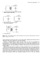
Figure 9.37 shows the relays necessary for interface protection as
well as some of the relays necessary for generator protection. Not all
Distributed Generation and Power Quality 431
Figure 9.37 Protection scheme for a large synchronous generator with high-
side recloser.
81 O/U 27/59 47 59 I 59 N
25
46 50/51V
DG
87G
32R 40 46 50/51
(GENERATOR PROTECTION)
51G
UTILITY
BREAKER OR
RECLOSER
GENERATOR
TRANSFORMER
ANOTHER
GENERATOR
Distributed Generation and Power Quality
Downloaded from Digital Engineering Library @ McGraw-Hill (www.digitalengineeringlibrary.com)
Copyright © 2004 The McGraw-Hill Companies. All rights reserved.
Any use is subject to the Terms of Use as given at the website.
the functions that might be necessary for proper control of the genera-
tor, interlocking of breakers, etc., are shown. This installation is com-
prised of multiple generators connected identically.
In this example, there is a primary-side utility breaker for which
utilities will typically use a common three-phase recloser. This is a con-
venient switchgear package for utilities to install and probably the
least costly as well. The recloser comes with overcurrent relaying (not
shown), and a separate DG relay package has been added that operates
off a separate potential transformer. This is the main breaker used to
achieve or ensure separation of the generator(s) from the utility.
The relaying elements in the system and their function are as fol-
lows.
Primary side
■
27/59: standard under/over voltage relay. This serves as the pri-
mary means of fault and island detection. This can be used to block
closing of the breaker until there is voltage present on the utility sys-
tem, or there may be a separate relay for that purpose.
■
81 O/U: standard over/under frequency relay for islanding detection.
■
47: negative-sequence voltage relay (optional). This is a backup
means for detecting utility-side faults that can be more sensitive than
voltage magnitudes in some cases. Also, it helps prevent generator
damage due to unbalance, although there is another relay for that
here.
■
59I: instantaneous (peak) overvoltage. This is a supplemental
islanding detection function. This would be employed in cases where
ferroresonance or other resonance phenomena are likely. This would
occur when utility-side capacitors interact with the generator reac-
tance. Since such overvoltages can cause damage quickly, the time
delay is much shorter than for the other relays—but not so short that
it trips on utility capacitor-switching transients.
■
59N (or 59G): neutral or ground overvoltage. This relay is installed
in the corner of a broken delta connection on the potential trans-
former. It is a supplemental fault and islanding detection relay func-
tion that measures the zero-sequence voltage. This would detect
conditions in which the generator is islanded on an SLG fault. It is
more necessary when the primary connection of the transformer is
delta or ungrounded-wye.
These relaying functions may be moved to the secondary side of the ser-
vice transformer if there is no high-side breaker. The relays would then
trip the main breaker on the secondary side.
432 Chapter Nine
Distributed Generation and Power Quality
Downloaded from Digital Engineering Library @ McGraw-Hill (www.digitalengineeringlibrary.com)
Copyright © 2004 The McGraw-Hill Companies. All rights reserved.
Any use is subject to the Terms of Use as given at the website.
No reverse power (32) function is used at this interface because net
export is expected.
Generator side
■
50/51: overcurrent relay. Responsible for tripping the main breaker
for faults within the generator system. May also trip for faults on the
utility system that the generator feeds. Therefore, the time delay
must be coordinated with the other relays so that it does not trip
inadvertently.
■
46 relay at transformer: negative-sequence current. Assists in the
detection of faults on the utility system, particularly open-phase con-
ditions, and trips the main breaker. (Generators have a separate 46
relay.)
■
25: synchronizing relay. Controls closing of the main breaker when
the generators are being interconnected to the utility. (This scheme
would also require synchronous check relays on the individual gen-
erators if they are to be interconnected separately.)
Generator protection
■
87G: differential ground relay. For fast detection of ground faults
within the generator.
■
51G: ground overcurrent. Trips the generator for high neutral cur-
rents indicative of a ground fault on the secondary system.
■
32R: reverse-power relay. This relay detects power going into the
generator, which would indicate a fault. Can be set very sensitive.
■
40: loss of field relay.
■
46: negative-sequence current. Protects the machine against exces-
sive unbalanced currents, which may result from an internal fault
but may also be due to unbalance on the utility system.
■
50/51: overcurrent relays. Protects the generator against excessive
loads and faults on either side of the generator breaker.
9.9 Summary
Readers might easily get the impression from the material in this chap-
ter that interconnecting a DG installation to the distribution system is
fraught with Gordian knot–like entanglement power quality problems.
However, few problems can be expected for most DG applications in the
near future while the total penetration is relatively low. There is a sig-
Distributed Generation and Power Quality 433
Distributed Generation and Power Quality
Downloaded from Digital Engineering Library @ McGraw-Hill (www.digitalengineeringlibrary.com)
Copyright © 2004 The McGraw-Hill Companies. All rights reserved.
Any use is subject to the Terms of Use as given at the website.
nificant amount of DG that can be accommodated without affecting the
operation of the distribution system, but there is a limit. The grid is not
infinite in capacity.
As a general rule, problems begin to appear when the total intercon-
nected DG capacity approaches 15 percent of the feeder capacity.
11,12
This might drop to as little as 5 percent of capacity on more rural feed-
ers or be as high as 30 percent if the DG is clustered near the substa-
tion. Voltage regulation problems are often the first to appear, followed
by interference with the utility fault-clearing process, which includes
concerns for islanding.
Changes can be made to accommodate nearly any amount of DG. As
the amount of DG increases, the simple, low-cost distribution system
design must be abandoned in favor of a more capable design. It will
almost certainly be more costly, but engineers can make it work.
Deciding who pays for it is another matter.
In a future of massively distributed generation, as some see it, com-
munications and control will be key. Today, most of the control of dis-
tribution systems is accomplished by local intelligence operating
autonomously. Systems with high penetrations of DG would benefit
greatly from fast, interconnected communications networks. This is
one technology shift that must accompany the spread of DG if it is to be
successful in contributing to reliable, high-quality electric power.
9.10 References
1. H. L. Willis and W. G. Scott, Distributed Power Generation Planning and Evaluation,
Marcel Dekker, New York, 2000.
2. N. Jenkins, R. Allan, P. Crossley, D. Kirschen, G. Strbac, Embedded Generation, The
Institute of Electrical Engineers, London, U.K., 2000.
3. W. E. Feero, W. B. Gish, “Overvoltages Caused by DSG Operation: Synchronous and
Induction Generators,” IEEE Transactions on Power Delivery, January 1986, pp.
258–264.
4. R. C. Dugan, D. T. Rizy, Harmonic Considerations for Electric Distribution Feeders,
ORNL/Sub/81-95011/4, Oak Ridge National Laboratory, U.S. DOE, March 1988.
5. IEEE Standard 929-2000, Recommended Practice for Utility Interface of Photovoltaic
Systems.
6. R. C. Dugan, T. E. McDermott, “Operating Conflicts for Distributed Generation on
Distribution Systems,” IEEE IAS 2001 Rural Electric Power Conference Record,
IEEE Catalog No. 01CH37214, Little Rock, Ark., May 2001, Paper No. 01-A3.
7. Electrical Distribution-System Protection, 3d ed., Cooper Power Systems, Franksville,
Wis., 1990.
8. R. H. Hopkinson, “Ferroresonance Overvoltage Control Based on TNA Tests of
Three-Phase Delta-Wye Transformer Banks,” IEEE Transactions on Power
Apparatus and Systems, Vol. 86, No. 10, October 1967, pp. 1258–1265.
9. D. R. Smith, S. R. Swanson, J. D. Borst, “Overvoltages with Remotely-Switched
Cable-Fed Grounded Wye-Wye Transformers,” IEEE Transactions on Power
Apparatus and Systems, Vol. PAS-94, No. 5, September/October 1975, pp. 1843–1853.
10. IEEE Standard P1547, Distributed Resources Interconnected with Electric Power
Systems, Draft 8, P1547 Working Group of IEEE SCC 21, T. Basso, Secretary.
434 Chapter Nine
Distributed Generation and Power Quality
Downloaded from Digital Engineering Library @ McGraw-Hill (www.digitalengineeringlibrary.com)
Copyright © 2004 The McGraw-Hill Companies. All rights reserved.
Any use is subject to the Terms of Use as given at the website.
11. Protection of Electric Distribution Systems with Dispersed Storage and Generation
(DSG) Devices, Oak Ridge National Laboratory, Report ORNL/CON-123, September
1983.
12. R. C. Dugan, T. E. McDermott, D. T. Rizy, S. Steffel, “Interconnecting Single-Phase
Backup Generation to the Utility Distribution System,” Transmission and
Distribution Conference and Exposition, 2001 IEEE/PES, Vol. 1, 2001, pp. 486–491.
9.11 Bibliography
Dugan, R. C., T. E. McDermott, G. J. Ball, “Distribution Planning for Distributed
Generation,” IEEE IAS Rural Electric Power Conference Record, IEEE Catalog No.
00CH37071, Louisville, Ky., May 7–9, 2000, pp. C4-1–C4-7.
Engineering Handbook for Dispersed Energy Systems on Utility Distribution Systems,
EPRI Final Report, TR-105589, November 1995.
Integration of Distributed Resources in Electric Utility Systems: Current Interconnection
Practice and Unified Approach, EPRI Final Report, TR-111489, November 1998.
“Interconnecting Distributed Generation to Utility Distribution Systems,” Short Course,
The Department of Engineering Professional Development, University of Wisconsin—
Madison, 2001.
Distributed Generation and Power Quality 435
Distributed Generation and Power Quality
Downloaded from Digital Engineering Library @ McGraw-Hill (www.digitalengineeringlibrary.com)
Copyright © 2004 The McGraw-Hill Companies. All rights reserved.
Any use is subject to the Terms of Use as given at the website.
Distributed Generation and Power Quality
Downloaded from Digital Engineering Library @ McGraw-Hill (www.digitalengineeringlibrary.com)
Copyright © 2004 The McGraw-Hill Companies. All rights reserved.
Any use is subject to the Terms of Use as given at the website.
437
10
Wiring and Grounding
Many power quality variations that occur within customer facilities are
related to wiring and grounding problems. It is commonly stated at
power quality conferences and in journals that 80 percent of all the
power quality problems reported by customers are related to wiring
and grounding problems within a facility. While this may be an exag-
geration, many power quality problems are solved by simply tightening
a loose connection or replacing a corroded conductor. Therefore, an
evaluation of wiring and grounding practices is a necessary first step
when evaluating power quality problems in general.
The National Electrical Code
®
(NEC
®
)* and other important standards
provide the minimum standards for wiring and grounding. It is often
necessary to go beyond the requirements of these standards to achieve a
system that also minimizes the impact of power quality variations (har-
monics, transients, noise) on connected equipment. While the intent of
this book is to concentrate on subjects that are more amenable to engi-
neering analysis, the basic principles of wiring and grounding are pre-
sented in this chapter to provide the reader with at least a fundamental
understanding of why things are done. References are provided through-
out the text for readers interested in further details.
10.1 Resources
Selected definitions are presented here from the IEEE Dictionary
(Standard 100), the IEEE Green Book (IEEE Standard 142), and the
NEC. These are the fundamental resources on wiring and grounding.
The IEEE Green Book and the NEC provide extensive information on
Chapter
*National Electrical Code
®
and NEC
®
are registered trademarks of the National Fire
Protection Association, Inc., Quincy, Mass. 02269.
Source: Electrical Power Systems Quality
Downloaded from Digital Engineering Library @ McGraw-Hill (www.digitalengineeringlibrary.com)
Copyright © 2004 The McGraw-Hill Companies. All rights reserved.
Any use is subject to the Terms of Use as given at the website.
proper grounding practices for safety considerations and proper system
operation. However, these documents do not address concerns for
power quality.
Power quality considerations associated with wiring and grounding
practices are covered in Federal Information Processing Standard
(FIPS) 94, Guideline on Electrical Power for ADP Installations (1983).
This is the original source of much of the information interpreted and
summarized here.
The IEEE Emerald Book (ANSI/IEEE Standard 1100-1992, IEEE
Recommended Practice for Powering and Grounding Sensitive
Electronic Equipment) updates the information presented in FIPS 94.
This is an excellent resource for wiring and grounding with respect to
power quality issues and is highly recommended.
Grounding guidelines to minimize noise in electronic circuits are also
covered in IEEE Standard 518, IEEE Guide for the Installation of
Electrical Equipment to Minimize Electrical Noise Inputs to Controllers
from External Sources. EPRI’s Wiring and Grounding for Power
Quality (Publication CU.2026.3.90) provides an excellent summary of
typical wiring and grounding problems along with recommended solu-
tions. Additional resources are provided in the Bibliography at the end
of this chapter.
10.2 Definitions
Some of the key definitions of wiring and grounding terms from these
documents are included here.
IEEE Dictionary (Standard 100) definition*
grounding A conducting connection, whether intentional or accidental, by
which an electric circuit or equipment is connected to the earth, or to some
conducting body of relatively large extent that serves in place of the earth.
It is used for establishing and maintaining the potential of the earth (or of
the conducting body) or approximately that potential, on conductors con-
nected to it; and for conducting ground current to and from the earth (or the
conducting body).
IEEE Green Book (IEEE Standard 142) definitions*
438 Chapter Ten
*Reprinted from IEEE Standard 100-1992, IEEE Standard Dictionary of Electrical and
Electronic Terms, copyright © 1993 by the Institute of Electrical and Electronics Engineers,
Inc. The IEEE disclaims any responsibility or liability resulting from the placement and
use in this publication. Information is reprinted with the permission of the IEEE.
Wiring and Grounding
Downloaded from Digital Engineering Library @ McGraw-Hill (www.digitalengineeringlibrary.com)
Copyright © 2004 The McGraw-Hill Companies. All rights reserved.
Any use is subject to the Terms of Use as given at the website.
ungrounded system A system, circuit, or apparatus without an intentional
connection to ground, except through potential indicating or measuring devices
or other very high impedance devices.
grounded system A system of conductors in which at least one conductor or
point (usually the middle wire or neutral point of transformer or generator
windings) is intentionally grounded, either solidly or through an impedance.
grounded solidly Connected directly through an adequate ground connection
in which no impedance has been intentionally inserted.
grounded effectively Grounded through a sufficiently low impedance such that
for all system conditions the ratio of zero sequence reactance to positive sequence
reactance (X0/X1) is positive and less than 3, and the ratio of zero sequence resis-
tance to positive sequence reactance (R0/X1) is positive and less than 1.
resistance grounded Grounded through impedance, the principal element of
which is resistance.
inductance grounded Grounded through impedance, the principal element
of which is inductance.
NEC definitions.
†
Refer to Fig. 10.1.
grounding electrode The grounding electrode shall be as near as practicable
to and preferably in the same area as the grounding conductor connection to
the system. The grounding electrode shall be: (1) the nearest available effec-
tively grounded structural metal member of the structure; or (2) the nearest
available effectively grounded metal water pipe; or (3) other electrodes (Section
250-81 & 250-83) where electrodes specified in (1) and (2) are not available.
grounded Connected to earth or to some conducting body that serves in place
of the earth.
grounded conductor A system or circuit conductor that is intentionally
grounded (the neutral is normally referred to as the grounded conductor).
grounding conductor A conductor used to connect equipment or the
grounded circuit of a wiring system to a grounding electrode or electrodes.
Wiring and Grounding 439
*Reprinted from IEEE Standard 142-1991, IEEE Recommended Practice for
Grounding of Industrial and Commerical Power Systems, copyright © 1991 by the
Institute of Electrical and Electronics Engineers, Inc. The IEEE disclaims any responsi-
bility or liability resulting from the placement and use in this publication. Information is
reprinted with the permission of the IEEE.
†
Reprinted with permission from NFPA 70-1993, the National Electrical Code
®
, copy-
right © 1993, National Fire Protection Association, Quincy, Mass. 02269. This
reprinted material is not the complete and official position of the National Fire
Protection Association on the referenced subject, which is represented only by the stan-
dard in its entirety.
Wiring and Grounding
Downloaded from Digital Engineering Library @ McGraw-Hill (www.digitalengineeringlibrary.com)
Copyright © 2004 The McGraw-Hill Companies. All rights reserved.
Any use is subject to the Terms of Use as given at the website.
grounding conductor, equipment The conductor used to connect the noncur-
rent-carrying metal parts of equipment, raceways, and other enclosures to the
system grounded conductor and/or the grounding electrode conductor at the
service equipment or at the source of a separately derived system.
grounding electrode conductor The conductor used to connect the ground-
ing electrode to the equipment grounding conductor and/or to the grounded
conductor of the circuit at the service equipment or at the source of a separately
derived system.
grounding electrode system Defined in NEC Section 250-81 as including: (a)
metal underground water pipe; (b) metal frame of the building; (c) concrete-
encased electrode; and (d) ground ring. When these elements are available,
they are required to be bonded together to form the grounding electrode sys-
tem. Where a metal underground water pipe is the only grounding electrode
available, it must be supplemented by one of the grounding electrodes specified
in Section 250-81 or 250-83.
bonding jumper, main The connector between the grounded circuit conductor
(neutral) and the equipment grounding conductor at the service entrance.
branch circuit The circuit conductors between the final overcurrent device
protecting the circuit and the outlets.
conduit enclosure bond (bonding definition) The permanent joining of
metallic parts to form an electrically conductive path, which will assure elec-
trical continuity and the capacity to conduct safely any current likely to be
imposed.
feeder All circuit conductors between the service equipment of the source of
a separately derived system and the final branch circuit overcurrent device.
440 Chapter Ten
N
G
N
G
BOND
NEC 250-26(e)
GROUNDING-ELECTRODE
CONDUCTOR
NEC 250-26(b)
GROUNDING ELECTRODE
NEC 250-26(c)
EARTH OR SOME CONDUCTING MATERIAL
EQUIPMENT GROUNDING
CONDUCTORS
G
N
L1
LOAD
INSULATED
NEUTRAL
METALLIC
CONDUCTOR
ENCLOSURE
NEC 250-91(b)
SYSTEM
OVERCURRENT
PROTECTION
SUPPLY
Figure 10.1 Terminology used in NEC definitions.
Wiring and Grounding
Downloaded from Digital Engineering Library @ McGraw-Hill (www.digitalengineeringlibrary.com)
Copyright © 2004 The McGraw-Hill Companies. All rights reserved.
Any use is subject to the Terms of Use as given at the website.
outlet A point on the wiring system at which current is taken to supply uti-
lization equipment.
overcurrent Any current in excess of the rated current of equipment or the
capacity of a conductor. It may result from overload, short circuit, or ground fault.
panel board A single panel or group of panel units designed for assembly in
the form of a single panel; including buses, automatic overcurrent devices, and
with or without switches for the control of light, heat, or power circuits;
designed to be placed in a cabinet or cutout box placed in or against a wall or
partition and accessible only from the front.
separately derived systems A premises wiring system whose power is
derived from a generator, a transformer, or converter windings and has no
direct electrical connection, including a solidly connected grounded circuit con-
ductor, to supply conductors originating in another system.
service equipment The necessary equipment, usually consisting of a circuit
breaker switch and fuses, and their accessories, located near the point of
entrance of supply conductors to a building or other structure, or an otherwise
defined area, and intended to constitute the main control and means of cutoff
of the supply.
ufer ground A method of grounding or connection to the earth in which the
reinforcing steel (rebar) of the building, especially at the ground floor, serves as
a grounding electrode.
10.3 Reasons for Grounding
The most important reason for grounding is safety. Two important
aspects to grounding requirements with respect to safety and one with
respect to power quality are
1. Personnel safety. Personnel safety is the primary reason that all
equipment must have a safety equipment ground. This is designed to
prevent the possibility of high touch voltages when there is a fault in a
piece of equipment (Fig. 10.2). The touch voltage is the voltage between
any two conducting surfaces that can be simultaneously touched by an
individual. The earth may be one of these surfaces.
There should be no “floating” panels or enclosures in the vicinity of
electric circuits. In the event of insulation failure or inadvertent appli-
cation of moisture, any electric charge which appears on a panel, enclo-
sure, or raceway must be drained to “ground” or to an object which is
reliably grounded.
2. Grounding to assure protective device operation. A ground fault
return path to the point where the power source neutral conductor is
grounded is an essential safety feature. The NEC and some local wiring
codes permit electrically continuous conduit and wiring device enclo-
sures to serve as this ground return path. Some codes require the con-
Wiring and Grounding 441
Wiring and Grounding
Downloaded from Digital Engineering Library @ McGraw-Hill (www.digitalengineeringlibrary.com)
Copyright © 2004 The McGraw-Hill Companies. All rights reserved.
Any use is subject to the Terms of Use as given at the website.
duit to be supplemented with a bare or insulated conductor included
with the other power conductors.
An insulation failure or other fault that allows a phase wire to make
contact with an enclosure will find a low-impedance path back to the
power source neutral. The resulting overcurrent will cause the circuit
breaker or fuse to disconnect the faulted circuit promptly.
NEC Article 250-51 states that an effective grounding path (the path
to ground from circuits, equipment, and conductor enclosures) shall
a. Be permanent and continuous
b. Have the capacity to conduct safely any fault current likely to be
imposed on it
c. Have sufficiently low impedance to limit the voltage to ground and
to facilitate the operation of the circuit protective devices in the
circuit
d. Not have the earth as the sole equipment ground conductor
3. Noise control. Noise control includes transients from all sources.
This is where grounding relates to power quality. Grounding for safety
reasons defines the minimum requirements for a grounding system.
Anything that is done to the grounding system to improve the noise
performance must be done in addition to the minimum requirements
defined in the NEC and local codes.
The primary objective of grounding for noise control is to create an
equipotential ground system. Potential differences between different
ground locations can stress insulation, create circulating ground cur-
rents in low-voltage cables, and interfere with sensitive equipment
that may be grounded in multiple locations.
Ground voltage equalization of voltage differences between parts of
an automated data processing (ADP) grounding system is accomplished
in part when the equipment grounding conductors are connected to the
grounding point of a single power source. However, if the equipment
grounding conductors are long, it is difficult to achieve a constant poten-
442 Chapter Ten
Line
Neutral
Safety Ground
System Ground
Fault
Load
Dangerous
Touch
Potential
Ungrounded
Cabinet
Figure 10.2 High touch voltage created by improper grounding.
Wiring and Grounding
Downloaded from Digital Engineering Library @ McGraw-Hill (www.digitalengineeringlibrary.com)
Copyright © 2004 The McGraw-Hill Companies. All rights reserved.
Any use is subject to the Terms of Use as given at the website.
tial throughout the grounding system, particularly for high-frequency
noise. Supplemental conductors, ground grids, low-inductance ground
plates, etc., may be needed for improving the power quality. These must
be used in addition to the equipment ground conductors, which are
required for safety, and not as a replacement for them.
10.4 Typical Wiring and Grounding
Problems
Sections 10.4.1 to 10.4.7 describe some typical power quality problems
that are due to inadequacies in the wiring and grounding of electrical
systems. It is useful to be aware of these typical problems when per-
forming site surveys because many of the problems can be detected
through simple observations. Other problems require measurements of
voltages, currents, or impedances in the circuits.
10.4.1 Problems with conductors and
connectors
One of the first things to be done during a site survey is to inspect the
service entrance, main panel, and major subpanels for problems with
conductors or connections. A bad connection (faulty, loose, or resistive)
will result in heating, possible arcing, and burning of insulation. Table
10.1 summarizes some of the wiring problems that can be uncovered
during a site survey.
Wiring and Grounding 443
TABLE 10.1 Problems with Conductors and Connectors
Problem observed Possible cause
Burnt smell at the panel, Faulted conductor,
junction box, or load bad connection, arcing, or
equipment overloaded wiring
Panel or junction box Faulty circuit breaker
is warm to the touch or bad connection
Buzzing (corona effect) Arcing
Scorched insulation Overloaded wiring, faulted
conductor, or bad connection
No voltage at load Tripped breaker, bad connection,
equipment or faulted conductor
Intermittent voltage at Bad connection or arcing
load equipment
Scorched panel or Bad connection or faulted conductor
junction box
Wiring and Grounding
Downloaded from Digital Engineering Library @ McGraw-Hill (www.digitalengineeringlibrary.com)
Copyright © 2004 The McGraw-Hill Companies. All rights reserved.
Any use is subject to the Terms of Use as given at the website.
10.4.2 Missing safety ground
If the safety ground is missing, a fault in the equipment from the phase
conductor to the enclosure results in line potential on the exposed sur-
faces of the equipment. No breakers will trip, and a hazardous situa-
tion results (see Fig. 10.2).
10.4.3 Multiple neutral-to-ground
connections
Unless there is a separately derived system, the only neutral-to-ground
bond should be at the service entrance. The neutral and ground should
be kept separate at all panel boards and junction boxes. Downline neu-
tral-to-ground bonds result in parallel paths for the load return current
where one of the paths becomes the ground circuit. This can cause
misoperation of protective devices. Also, during a fault condition, the
fault current will split between the ground and the neutral, which
could prevent proper operation of protective devices (a serious safety
concern). This is a direct violation of the NEC.
10.4.4 Ungrounded equipment
Isolated grounds are sometimes used due to the perceived notion of
obtaining a “clean” ground. The proper procedure for using an isolated
ground must be followed (see Sec. 10.5.5). Procedures that involve hav-
ing an illegal insulating bushing in the power source conduit and
replacing the prescribed equipment grounding conductor with one to
an “isolated dedicated computer ground” are dangerous, violate code,
and are unlikely to solve noise problems.
10.4.5 Additional ground rods
Ground rods should be part of a facility grounding system and con-
nected where all the building grounding electrodes (building steel,
metal water pipe, etc.) are bonded together. Multiple ground rods can
be bused together at the service entrance to reduce the overall ground
resistance. Isolated grounds can be used for sensitive equipment, as
described previously. However, these should not include isolated
ground rods to establish a new ground reference for the equipment.
One very important power quality problem with additional ground rods
is that they create additional paths for lightning stroke currents to
flow. With the ground rod at the service entrance, any lightning stroke
current reaching the facility goes to ground at the service entrance and
the ground potential of the whole facility rises together. With addi-
tional ground rods, a portion of the lightning stroke current will flow on
the building wiring (green ground conductor and/or conduit) to reach
444 Chapter Ten
Wiring and Grounding
Downloaded from Digital Engineering Library @ McGraw-Hill (www.digitalengineeringlibrary.com)
Copyright © 2004 The McGraw-Hill Companies. All rights reserved.
Any use is subject to the Terms of Use as given at the website.
the additional ground rods. This creates a possible transient voltage
problem for equipment and a possible overload problem for the con-
ductors.
10.4.6 Ground loops
Ground loops are one of the most important grounding problems in
many commercial and industrial environments that include data pro-
cessing and communication equipment. If two devices are grounded via
different paths and a communication cable between the devices pro-
vides another ground connection between them, a ground loop results.
Slightly different potentials in the two power system grounds can cause
circulating currents in this ground loop if there is indeed a complete
path. Even if there is not a complete path, the insulation that is pre-
venting current flow may flash over because the communication circuit
insulation levels are generally quite low.
Likewise, very low magnitudes of circulating current can cause
serious noise problems. The best solution to this problem in many
cases is to use optical couplers in the communication lines, thereby
eliminating the ground loop and providing adequate insulation to
withstand transient overvoltages. When this is not practical, the
grounded conductors in the signal cable may have to be supplemented
with heavier conductors or better shielding. Equipment on both ends
of the cable should be protected with arresters in addition to the
improved grounding because of the coupling that can still occur into
signal circuits.
10.4.7 Insufficient neutral conductor
Switch-mode power supplies and fluorescent lighting with electronic
ballasts are widely used in commercial environments. The high third-
harmonic content present in these load currents can have a very impor-
tant impact on the required neutral conductor rating for the supply
circuits.
Third-harmonic currents in a balanced system appear in the zero-
sequence circuit. This means that third-harmonic currents from three
single-phase loads will add in the neutral, rather than cancel as is the
case for the 60-Hz current. In typical commercial buildings with a
diversity of switched-mode power supply loads, the neutral current is
typically in the range 140 to 170 percent of the fundamental frequency
phase current magnitude.
The possible solutions to neutral conductor overloading include the
following:
■
Run a separate neutral conductor for each phase in a three-phase cir-
cuit that serves single-phase nonlinear loads.
Wiring and Grounding 445
Wiring and Grounding
Downloaded from Digital Engineering Library @ McGraw-Hill (www.digitalengineeringlibrary.com)
Copyright © 2004 The McGraw-Hill Companies. All rights reserved.
Any use is subject to the Terms of Use as given at the website.
■
When a shared neutral must be used in a three-phase circuit with
single-phase nonlinear loads, the neutral conductor capacity should
be approximately double the phase conductor capacity.
■
Delta-wye transformers (see Sec. 10.5.6) designed for nonlinear loads
can be used to limit the penetration of high neutral currents. These
transformers should be placed as close as possible to the nonlinear
loads (e.g., in the computer room). The neutral conductors on the sec-
ondary of each separately derived system must be rated based on the
expected neutral current magnitudes.
■
Filters to control the third-harmonic current that can be placed at
the individual loads are becoming available. These will be an alter-
native in existing installations where changing the wiring may be an
expensive proposition.
■
Zigzag transformers provide a low impedance for zero-sequence har-
monic currents and, like filters, can be placed at various places along
the three-phase circuit to shorten the path of third-harmonic currents
and better disperse them.
10.5 Solutions to Wiring and Grounding
Problems
10.5.1 Proper grounding practices
Figure 10.3 illustrates the basic elements of a properly grounded elec-
trical system. The important elements of the electrical system grounding
are described in Secs. 10.5.2 to 10.5.5.
446 Chapter Ten
N N
SERVICE
TRANSFORMER
FEEDER
PANEL
BOARD
BRANCH
CIRCUIT
LOAD
Receptacle
Conduit/Enclosure
Building
Grounding
Electrode
Grounding-
Electrode
Conductor
BUILDING
SERVICE
EQUIPMENT
Bonding
Jumper
Grounding
Electrode
Grounded
Service
Conductor
Phase Conductor
(Hot)
Grounded Conductor
(Neutral)
Insulated
Ground Conductor
(Green Wire)
GG
Figure 10.3 Basic elements of a properly grounded electrical system.
Wiring and Grounding
Downloaded from Digital Engineering Library @ McGraw-Hill (www.digitalengineeringlibrary.com)
Copyright © 2004 The McGraw-Hill Companies. All rights reserved.
Any use is subject to the Terms of Use as given at the website.