MANAGEMENT DYNAMICS Merging Constraints Accounting to Drive Improvement phần 7 pdf
Bạn đang xem bản rút gọn của tài liệu. Xem và tải ngay bản đầy đủ của tài liệu tại đây (434.35 KB, 33 trang )
2. If the order appears to be in the 3% group, annotate the Buffer
Hole Report to reflect the status and next action date if appropriate.
Job #20 will be checked again on August 19 to be certain that it is
still on track for on-time shipment.
3. If the order appears to be in the 3% group, but a specific next check
time is not known, monitor the item on a regular basis to ensure its
on-time shipment.
4. If the order appears to be in the 1% group or is too close to call (err
on the side of paranoia here), take appropriate actions to expedite
the item.
Job #30 has a promise to ship to Peterson Manufacturing by August
22. However, it appears that the vacation schedule of one of our employ-
ees, Rob Davis, is about to become a problem for our customer, Peterson
Manufacturing. This report will have widespread distribution, and the
general culture of the organization will probably determine whether this
happens. If the culture is such that the members of the organization un-
derstand what needs to be done, and there is a motivating reason for
them to do it, then there is a good chance that somebody will take the ini-
tiative to see whether the approval can come from elsewhere.
Job #40 makes its first appearance on the report today. The com-
ment, EXPEDITE, is generated by the computer software in the absence of
other comments. Its purpose is to alert all report recipients that this item
is in danger of missing its shipping date and that no corrective action has
yet been identified.
The buffer manager, a new position for organizations undertaking
constraint management, will follow up on this item. When its status is de-
termined more fully, the appropriate comments will be added to the re-
port. If the item appears to be a 1% type of item, the buffer manager will
also immediately initiate appropriate expediting actions.
The DBR system subordinates the production flow to the schedule of
the constraints. Buffers accommodate the statistical fluctuations inherent
in the system. When the statistical fluctuation exceeds the safety provided
by the buffer, buffer management identifies the relatively few specific or-
ders that need to have special attention.
Buffer Hole Pareto Analysis
A final aspect of buffer management involves focusing attention on the ar-
eas where the greatest difference for improvement can be made. As illus-
trated in Exhibit 7.9, orders that cause buffer holes in the expedite zone
are likely to have become stuck at some point in the system.
Product will tend to become “stuck” at areas that either are not sub-
Buffer Management Reporting 185
5070_Pages 7/14/04 1:55 PM Page 185
ordinating properly (the most frequent case) or that do not have ade-
quate protective capacity. A Pareto analysis of where in the process the or-
ders that have created buffer holes are located can identify the areas that
are not subordinating well or have inadequate protective capacity. Al-
though the product may be anywhere in the process at any given time, it
will most frequently be found in the problem area. A tracking zone is es-
tablished for this purpose.
16
When a buffer hole appears in the tracking
zone of the buffer, we do not take extraordinary actions but rather simply
determine the source (current product location) of the hole. The location
should be recorded by time period and resource. These data may be sum-
marized as a histogram for individual resources, as illustrated in Exhibit
7.10. The same data are shown in a statistical format in Exhibit 7.11, and
Exhibit 7.12 portrays similar data over time.
These data will help establish priorities for nonconstraint enhance-
ment. Exhibits 7.10 through 7.12 show that the welder is the primary
source of schedule disruptions. Exhibit 7.12, which shows a comparison of
resource areas over time, also illustrates that we would not expect the data
to be static. In fact, the Exhibit 7.12 data indicate that in week 3 the
grinder was a greater source of schedule disruption than the welder. The
grinder data for week 3 may have been due to a machine malfunction, em-
ployee absenteeism, or some other cause. Weeks 4 and 5 still show the
grinder at above-average amounts, but it is probably under control again,
with the decreasing higher levels representing catching-up.
Problems in Support Areas
Buffer management will also detect many problems in support areas. Sup-
port areas are not directly reflected in buffer hole reporting because
buffer holes are traced only to areas that actually work on the product.
186 Tactical Subordination in Manufacturing
Exhibit 7.9 Tracking Source of Buffer Holes
The buffer manager
tracks the location of
jobs that have created
buffer holes.
XX
XX
XX
XX
XX
XX
XX
XX
XX
XX
XX
XX
XX
XX
XX
XX
XX
XX
XX
XX
XX
XX
XX
XX
XX
XX
XX
XX
XX
XX
XX
XX
XX
XX
XX
XX
XX
XX
XX
XX
XX
XX
XX
XX
XX
XX
XX
XX
XX
XX
XX
XX
XX
XX
XX
XX
XX
XX
XX
XX
XX
XX
XX
XX
XX
XX
Some product
is "stuck."
Manufacturing Flow
5070_Pages 7/14/04 1:55 PM Page 186
However, the initial tracing is only a starting point. Is the area an emerg-
ing or near constraint? Is the area waiting for an approval or some other
administrative procedure? Tracing and recording the next level of cause
will result in detecting support areas in need of attention.
SUMMARY
Recall that tactical subordination refers to subordinating to the exploita-
tion decisions for tactical, or currently active, constraints and that most
day-to-day operating activities fall into this category. Buffer management
as defined in constraint management completely replaces conventional
management reporting systems. Constraints accounting supports buffer
management by providing information that can be used to identify emerg-
Summary 187
Exhibit 7.10 Histogram Summarizing Buffer Hole Source
XXX
XXX
XXX
XXX
XXX
XXX
XXX
XXX
XXX
XXX
XXX
XXX
XXX
XXX
XXX
XXX
XXX
XXX
XXX
XXX
XXX
Welder Cutter Polisher Grinder Assembler
Exhibit 7.11 Statistical Presentation Summarizing Buffer Hole Source
Resource Frequency Percent
Welder 11
2
1
3
52
Cutter 10
Polisher 5
Grinder 94
Assembler 14
5070_Pages 7/14/04 1:55 PM Page 187
ing constraints. Constraints accounting replaces legacy accounting effi-
ciency reporting systems. When this happens, the two systems constraint
management and constraints accounting merge into one. Buffer manage-
ment gives all members of the organization the security of knowing that
they are taking appropriate action, since the information provided by the
buffers allows knowledgeable employees at all levels to respond appropri-
ately to statistical fluctuations and changing demands on the system. The
replacement of legacy control systems with buffer management incorpo-
rating buffer reporting is a key to locking in a process of ongoing im-
provement.
NOTES
1
Eliyahua M. Goldratt and Robert E. Fox, The Race (North River Press, 1986);
Eliyahua M. Goldblatt, The Haystack Syndrome: Sifting Information Out of the Data
Ocean (North River Press, 1991); Eli Schragenheim and H. William Dettmer,
Manufacturing at Warp Speed: Optimizing Supply Chain Financial Performance (CRC
Press, 2000); and Mark J. Woeppel, Manufacturers Guide to Implementing the Theory of
Constraints (St. Lucie Press, 2001).
2
A strategic pseudo-constraint would be used as a drum resource in order to
prevent the standard operating procedures for manufacturing from changing
when the tactical constraint oscillates back between the market and a strategic
internal constraint.
3
We assume that the organization has at least a relatively inexpensive computer
system appropriate for the size and nature of the business. For example, the
Microsoft Office software suite or its equivalent could provide the basic software.
We assume the availability of a web browser, spreadsheet, and relational database
for our discussions.
4
Recall that the buffer is a time buffer. The buffer size is the same thing as the
rope length.
188 Tactical Subordination in Manufacturing
Exhibit 7.12 Source of Shipping Buffer Holes by Week
0
123 5 7864
5
10
15
Welder
Week
Number of holes
Cutter
Polisher
Grinder
Assembler
5070_Pages 7/14/04 1:55 PM Page 188
5
Since the buffer size (rope length) is established in a heuristic manner, based on
actual operations, the rope length is the amount of time required to reliably ship
a product on time. Therefore, in a make-to-order environment the quoted lead
time must be at least as long as the rope.
6
Goldratt has recommended 5% as a starting place (Goldratt Satellite Program Tape
1, 1999). The organization’s actual experience will provide some guidance as to
how to adjust these parameters on an ongoing basis.
7
The data shown in Exhibit 7.5 assume that the organization ships an average of
100 orders each day, with a maximum of 200 orders and a minimum of zero
orders on any particular day. The average of orders that create a hole in the
expedite zone of the buffer on any particular day is 4% +/−1.5% of total orders
shipped that day but is rounded to the nearest whole number. Within those
ranges, the data are generated as a uniform random number. Data are not shown
for days on which fewer than 40 items were shipped because the control limits
would be measuring in greater detail than the interval of the data justify. For
example, if 10 orders were shipped, 4% expedites would be 0.04 * 10 = 0.4
expedites. Since we only deal with whole orders, we would expect either zero
expedites (0%) or one expedite (10%), each of which lies outside the control
limits.
8
Realistic data are likely to have a much greater variance than the data used in
the illustrations. Therefore, it will not be unusual for observations to fall outside
the control limits. This is not a cause for concern, and corrective action is not
needed based on this chart (Exhibit 7.6). Other measurements will indicate
specific areas of concern.
9
We often think of protective capacity as being a function of individual resources
only. However, Schragenheim and Dettmer have shown through simulation
studies that it is also a function of the overall protective capacity in the system.
Information on their simulation offerings may be obtained at
as of February 25, 2004.
10
Note that if the new rope length, for example, 18 days, is still less than the
quoted lead time, this action will have no immediate effect beyond the
production function. However, if the rope were now longer than the quoted lead
time, then it would also be necessary to coordinate with sales and marketing.
11
For example, at the Electronic Division of the Ford Motor Company the
average (for all sites and all products) time required from material release to
shipping was 10.6 days. After two years of just-in-time (JIT) implementation, the
average time had been reduced to 8.5 days. This was further reduced during one
year of TOC implementation to 2.2 days and subsequently to less than two shifts.
(Source: Avraham Y. Goldratt Institute web site, www.goldratt.com request article,
ford.htm, August 1, 2001).
12
If giving that job priority creates a fatal conflict (a fatal conflict in this case is
one that results in a shipping date being missed) with another job that has also
caused a hole in the expedite zone, then a responsible manager needs to make a
decision as to which customer’s order will be shipped on time and which customer
is to be offended.
13
Having the item remain on the report ensures that someone looks at it on a
regular basis. If there are so many of these long-overdue items on a buffer hole
report that they are routinely ignored or they obscure the more recent data, then
these might be moved to a separate report. Sometimes a separate field for a
revised shipping date is added to the database.
14
The Buffer Hole Report might be a hard copy report or a virtual report
available electronically on demand.
Notes 189
5070_Pages 7/14/04 1:55 PM Page 189
15
We are continually amazed at the number of people who believe that their
customers prefer the quote of a short promised delivery date (say 7 days) which is
missed 20 to 40% of the time (and with a large variance) to a reliable promise
(say 15 days) that ships on time over 99.7% of the time.
16
The tracking zone may be the same as the expedite zone. However, it may
prove useful to start the tracking earlier in order to deepen the statistic. About
one-half of the rope length or checking about 40% of the orders has been
suggested. See Goldratt, The Haystack Syndrome, pp. 139–140.
190 Tactical Subordination in Manufacturing
5070_Pages 7/14/04 1:55 PM Page 190
8
Tactical Subordination
in Project Management
Our second example of constraints accounting support for tactical subor-
dination relates to a project management environment. In this environ-
ment the constraint management application is known as the critical
chain.
1
Even though the critical chain is a relatively new constraint man-
agement application, it is already reported as being extremely powerful
with respect to project management.
2
As with the drum-buffer-rope appli-
cation in manufacturing, the constraints accounting focus will again be on
time buffers. In critical chain project management, the buffers are associ-
ated with individual projects as well as a drum resource.
Two aspects of critical chain project management differ from con-
ventional project management. First, is the notion of a critical chain,
which is the longest set of dependent activities from the start to the com-
pletion of a project explicitly, considering the availability of resources?
The second, and more significant, difference from conventional project
management lies in the way projects are scheduled and managed. We start
our discussion of the critical chain environment by examining how people
use common sense to protect their promises.
COMMON-SENSE SCHEDULING
In order to schedule the various parts of a project, an estimate of the dura-
tion—or time required—for each individual component (activity or task)
is needed. How long will it take to complete an individual activity or task?
The estimate of the time required for a given task, when accepted by those
charged with responsibility for the task, also becomes a promise of deliv-
ery date to the next activity in the project.
Let us assume that 10 days is an accurate estimate of the average
191
5070_Pages 7/14/04 1:55 PM Page 191
time required for a resource, A, to complete a task, Y.
3
We might represent
this task A–Y as shown in Exhibit 8.1.
Put five tasks, each similar to the A–Y task together as a simple proj-
ect. How long does it take to complete the project? If each of the five tasks
requires 10 days, the project should progress as shown in Exhibit 8.2. The
overall project should take 50 days (5 tasks * 10 days per task) to com-
plete.
Given the normal statistical fluctuations of day-to-day operations,
task A–Y could be completed in less than 10 days one-half of the time.
However, one-half of the time task A–Y will require more than 10 days.
Will this have an effect on our project? That is, will sensible people really
schedule the project as though each task will be completed in its median
time?
Not completing task A–Y on time one-half (50%) of the time may be
expected to have a significant adverse effect on the next resource in the
project, which will be unable to schedule its work reliably.
4
Since people
like to deliver what they promised, such an unreliable situation is objec-
tionable to everyone. Supervisors will not be able to schedule efficiently.
Those performing the work will be under pressure to deliver work that is
not completed by the scheduled time (and half of the work will fall into
this category). Sensible people who want to keep their promises prevent
this situation by adding some safety time to the estimate.
Enough safety is added to the time estimate for the task to allow it to
be completed within the estimated duration about 90% of the time. Most
people seem to feel that this 90% estimate is reasonable. If it appears that
192 Tactical Subordination in Project Management
Exhibit 8.1 Median Time Required for Resource and Task
Resource
and Task
Median
Time Required
10 days
A–Y
Exhibit 8.2 Project Progress
1
(10)
2
(10)
3
(10)
4
(10)
5
(10)
5070_Pages 7/14/04 1:55 PM Page 192
a particular activity will fall into the 10% tail of the distribution, then ex-
pediting actions will be taken to meet the 90% estimate. These relation-
ships are shown in Exhibit 8.3.
In order for task A–Y to be completed (without expediting) within
its estimated duration 90% of the time, it will be necessary to allow 18 days
for the task. That is, 8 days of safety will be added to the estimate as re-
flected in Exhibit 8.4.
Our previous simple project, linking five similar tasks together, did
not consider the need for safety in the scheduling. Adding safety to each
task, we arrive at the sequence shown in Exhibit 8.5. This becomes the
schedule for the project. Now each of the five tasks is allowed 18 days—10
days for the median time required plus 8 days of safety. The overall project
should take 90 days (5 tasks * 18 days per task) to complete.
When the project is actually undertaken, it may or may not be com-
pleted within the scheduled amount of time. A typical portrayal of actual
operations as compared to the schedule is reflected in Exhibit 8.6.
The first task is completed earlier than expected (8 days as opposed
to the 10-day average). However, the people involved in this first task do
not report its completion until the entire time allowed (18 days) has
passed. The second activity is also completed in less than the average time
(6 days), but true to Parkinson’s Law
5
the person doing this second task
manages to stretch it out to the full 18 days scheduled. The third task is fin-
Common-Sense Scheduling 193
Exhibit 8.3 Distribution of Actual Time Required for Task A–Y
Actual Days Required to Complete Task
Frequency
Complete most
tasks by
promised time
Protect against the tail by expediting
18 days allows on-time completion 90% of the time.
10 days allows on-time completion 50% of the time.
5070_Pages 7/14/04 1:55 PM Page 193
ished in slightly more than the average time (12 days actual as opposed to
10 days average) but well within the safety allowed for the task. Neverthe-
less, the fourth task is not started until its scheduled time. The fourth task
encounters difficulty and takes longer than even its safety time, delaying
the starting time for the fifth task. The fifth task is completed in 16 days
and within its allotted time of 18 days, but the entire project is nonetheless
late. There were—or could have been—early finishes for three of the five
tasks. Three factors, (1) delayed reporting, (2) Parkinson’s Law, and (3)
scheduling wait squander the safety. The overall project does not get the
advantage of the safety built into each task. We must conclude that adding
safety time to each individual task, though improving the probability of
each individual resource meeting its internal delivery date, fails as a safety
mechanism when viewed from the perspective of the project as a whole.
Each of the first three types of delay observed in Exhibit 8.6 is re-
lated to the existence of a schedule for the individual tasks in the project.
Only the fourth type of delay, in which the task was actually completed
late, was an attribute of the task itself. Although the first task was com-
pleted in only 8 days, the completion was not reported until all 18 days al-
lowed had passed. But note that the very concept of an early completion
carries the connotation of a promised completion date. Some aspect of the
organization’s culture must discourage the reporting of early completion. In the
second task, the operator could have completed the task early but instead
chose to drag it out to fully consume the 18 days allowed. This instance of
194 Tactical Subordination in Project Management
Exhibit 8.5 Adding Safety to Each Task
1
(10)
2
(10)
3
(10)
4
(10)
5
(10)
Safety
(8)
Safety
(8)
Safety
(8)
Safety
(8)
Safety
(8)
Exhibit 8.4 10-Day Task with Safety Time
Resource and Task
Median Time
Safety
90% on time
Time Required
10 days + 8 days = 18 days
A–Y
Safety
A–Y
Safety
5070_Pages 7/14/04 1:55 PM Page 194
Parkinson’s Law is dependent on the concept of the time allowed, which
in turn depends on the promised completion date reflected in the sched-
ule. Again, something in the culture must discourage early task comple-
tion. The third type of delay, waiting for the scheduled start time before
starting the task, is also dependent on having a scheduled time. Finally,
note that none of the three delays related to scheduling caused a task to
extend beyond its promised completion.
6
The major part of the delay in the project is caused by the combina-
tion of having a schedule for each task and the promises of individuals in
the organization with respect to the schedule. Eliminating the schedule
could perhaps eliminate this type of delay. Experience has shown that a
chain of activities can be protected to about the 90% level, with approxi-
mately one-half as much safety as is necessary to protect each individual
activity to 90%.
7
It is also useful to set no specific interim delivery dates for
an individual chain of activities.
What would happen if the individual tasks of the project were simply
sequenced, rather than scheduled, and if the organizational culture changed
so much that the implied promise was for all members of the organization to
do their best rather than to meet a schedule for individual tasks?
8
The questions just posed do not eliminate the need for safety time in
the estimates, but it adjusts the positioning of the safety from being associ-
ated with individual tasks to being associated with the project as a whole.
The sequence estimate (based on the median time), associated safety, and
actual results for our project would then appear as reflected in Exhibit 8.7.
Again, the first task is completed in 8 days. Because there is no
scheduled completion date and the culture is different, there is no pres-
Common-Sense Scheduling 195
Exhibit 8.6 Actual Operations Compared to Schedule
(1) Delayed Reporting
1 2 3 4 5
Safety Safety Safety Safety Safety
Schedule
1
2
3 4 5
Actual
(2) Parkinson’s Law
(3) Schedule Wait
(4) Task Completes Late
5070_Pages 7/14/04 1:55 PM Page 195
sure to delay reporting completion of the task. The second task, which
could have been completed in 6 days, is again stretched out to 18 days.
Even though the culture of the organization is changing, there will likely
be a residual memory because cultural change does not take place instan-
taneously. The person working on the second task may not trust the man-
agers who have told him that it is “OK” to complete the task as quickly as
possible (and, as a consequence, display considerable amount of idle
time).
9
So the second task is shown as lasting 18 days. The third, fourth,
and fifth tasks are completed in the same amounts of time as in the previ-
ous example: 12, 22, and 16 days, respectively. As a result, the entire proj-
ect is completed well within the time allowed for the entire project.
We must conclude that it is more effective to have safety time associ-
ated with the project as a whole rather than with individual tasks within
the project. Less total safety is needed to protect a chain of activities than
is needed to protect each activity individually. We will now turn our atten-
tion to the concept of a critical chain, and then we will combine the criti-
cal chain with our new understanding of common-sense sequencing as op-
posed to scheduling.
CRITICAL PATH VERSUS CRITICAL CHAIN
Consider the project network shown in Exhibit 8.8.
10
This project net-
work, consisting of five tasks, has an upper and a lower leg. On the upper
leg, task V must be completed before task W, and on the lower leg task X
must be completed before task Y. Both tasks W and Y must be completed
before work can begin on task Z. The distinction between a critical path
and the critical chain is illustrated in Exhibits 8.9 and 8.10. The time esti-
196 Tactical Subordination in Project Management
Exhibit 8.7 Sequence Estimates, Associated Safety, and Actual Results
1
2 3 4 5
Safety Safety Safety Safety Safety
Sequence Estimate
1
2 3 4 5
Actual
(2) Parkinson’s Law
5070_Pages 7/14/04 1:55 PM Page 196
mates shown in Exhibit 8.8 are typical 90% estimates (i.e., they include
safety time for each task). The time estimates shown in Exhibit 8.8 are typ-
ical 90% estimates—that is, safety is included for each task. Exhibit 8.9
shows a conventionally computed critical path.
11
Going along the top path, task V is expected to require 14 days to
complete; task W to require 6 days; and task Z 4 days. Therefore, the top
path requires 24 days to complete (14 + 6 + 4 = 24). On the lower path,
task X is expected to require 6 days, task Y 10 days, and task Z 4 days. The
lower path is expected to require only a total of 20 days to complete. The
conventionally computed critical path is the top path (start—task 1—task
2—task 5—end), requiring 24 days, and is highlighted by the dotted ar-
rows. This path appears to be critical because any delay on this path will
cause a delay for the entire project.
Resource A, however, is used for both task V and task Y. Since a given
resource can do only one thing at a time, resource A cannot start on task Y
until it has first completed task V. Therefore, the longest sequence of ac-
tivities through the network will actually be start—task V—task Y—task Z—
end as highlighted by the dashed arrows in Exhibit 8.10.
12
The longest sequence of tasks requires 28 days for completion of the
project (14 + 10 + 4 = 28). This sequence, which incorporates the depend-
ency relationships that exist among the various resources comprising the
organizational tangle of chains, is known as the critical chain. The critical
chain may, or may not, be the same as the critical path.
We will complete our discussion of the critical chain environment by
combining the critical chain concept with our observations about
common-sense sequencing for single- and multiproject settings.
PROJECT MANAGEMENT CONSTRAINTS
We have not mentioned constraints thus far in our project management dis-
cussion. Since the critical chain of activities controls the duration of a proj-
Project Management Constraints 197
Exhibit 8.8 Project Network
Task V
14 days
Resource
A
Task W
6 days
Resource
B
Task X
6 days
Resource
C
Task Y
10 days
Resource
A
Task Z
4 days
Resource
D
Start End
5070_Pages 7/14/04 1:55 PM Page 197
ect, the critical chain is frequently regarded as analogous to a constraint.
13
From the constraints accounting point of view, this analogy is inaccurate. We
will not consider the critical chain to be identical to a constraint. Critical
chain project management cannot have a powerful bottom-line impact if
applied only in a local, nonconstrained area of operations. It must be associ-
ated with a global constraint to have a significant bottom-line impact. In
fact, the constraint of an organization may not even lie on the critical chain
of a given project. We will refer to a critical chain as a critical chain, and we
will reserve the word constraint for bottom-line limiting factors. In similar
fashion, we will restrict the term exploit to decisions relating to constraints
and the term subordination to the exploitation decisions. If we do not use
these terms carefully, we may seduce ourselves into thinking that we are do-
ing constraint management when, in fact, we are only optimizing locally.
Critical Chain
Even though the critical chain may not be a constraint within our meaning
of the word, viewing the critical chain as a leverage point and applying the
198 Tactical Subordination in Project Management
Exhibit 8.9 Conventional Critical Path
Task V
14 days
Resource
A
Task W
6 days
Resource
B
Task X
6 days
Resource
C
Task Y
10 days
Resource
A
Task Z
4 days
Resource
D
Start End
Exhibit 8.10 Critical Chain
Task V
14 days
Resource
A
Task W
6 days
Resource
B
Task X
6 days
Resource
C
Task Y
10 days
Resource
A
Task Z
4 days
Resource
D
Start End
5070_Pages 7/14/04 1:55 PM Page 198
subordination rule to it have allowed the combination of common-sense
sequencing with the critical chain concept to produce the critical chain
project management technique. Traditionally, a project is considered suc-
cessful if it is completed on time and within budget while maintaining the
desired scope. Most projects suffer from the types of delays observed in
Exhibit 8.6 (delayed reporting, Parkinson’s Law, waits for scheduled start
times, late completions). As a result, most projects fail one or more of the
traditional criteria for success.
Single-Project Sequencing
We will examine sequencing for a single project first. The critical chain
project sequencing technique concentrates safety at the end of chains of
activities. This safety time, provided at the end of a sequence of activities,
is another type of time buffer. The buffer represents time that is not in
general expected to be used but that must be provided for, if projects are
to be completed on time reliably. Exhibit 8.11 shows the same project as
illustrated in Exhibit 8.10 rescheduled, with estimated task durations cut
in half and project and feeding time buffers inserted.
The changes made when inserting the safety time buffers into the
project are as follows.
• Estimated task times have been cut in half to remove safety from
the task estimate and have a 50% chance of completing task in
scheduled time. That is, the median time is used rather than the
90% estimate.
14
Project Management Constraints 199
Exhibit 8.11 Critical Chain with Buffers
Task V
7 days
Resource
A
Task W
3 days
Resource
B
Task X
3 days
Resource C
Task Y
5 days
Resource
A
Task Z
2 days
Resource
D
Start
End
Feeding
Buffer
1.5 days
Feeding
Buffer
1.5 days
Project
Buffer
7 days
5070_Pages 7/14/04 1:55 PM Page 199
• One-half of the safety time removed from the individual task esti-
mates, reflecting the statistical phenomenon that an entire chain of
events can be protected with less total safety than protecting each of
the individual tasks, is added back in the form of time buffers:
• A project buffer equal to one-half of the restated critical chain
task times is placed at the end of the chain.
• Feeding buffers equal to one-half of the task time on the feed-
ing chains are placed where noncritical chain tasks integrate
with the critical chain.
15
The critical chain after insertion of the buffers is start—task V—task
Y—task Z—project buffer—end. This chain requires 21 days (7 + 5 + 2 + 7 =
21). The result is that the estimated overall length of time expected to
complete the project schedule is reduced from 28 days (Exhibit 8.10) to
21 days (Exhibit 8.11). The same project is shown as a Gantt chart high-
lighting relative times in Exhibit 8.12.
In Exhibit 8.12 the three critical chain activities and project buffer
have been placed on the same line within the bold outlined box. The proj-
ect buffer is one-half the length of the sum of the activities on the critical
chain.
16
The noncritical chain activities are shown as feeding into the criti-
cal chain at the appropriate points. Feeding buffers protect the critical
chain from disruptions on the feeding paths. Safety included in the feed-
ing buffers does not increase the estimated completion date of a project,
but safety included in the project buffer does extend the estimated com-
pletion date.
Sequencing and buffering a single project plan is useful for organi-
zations that do projects only occasionally. Many organizations operate in a
200 Tactical Subordination in Project Management
Exhibit 8.12 Gantt Chart Showing Relative Times
V–A Y–A Z–D
Pro
j
ect Buffer
X–C FB
W–B FB
Estimated
Completion
Feeding Buffers (FB)
Project
Completion
Critical Chain
5070_Pages 7/14/04 1:55 PM Page 200
multiproject environment, either as the nature of their products (e.g.,
construction) or as specific areas within the organization (e.g., engineer-
ing). In the latter case, resource contention among the several projects
must be resolved.
Multiple-Project Sequencing
We saw that the specific resolution of resource competition within the
project network is the distinguishing feature for the critical chain of a
project, as contrasted with a critical path. In a multiproject environment,
several projects may contend for the same resource. Consider the three
projects represented in Exhibit 8.13.
The three projects individually have been sequenced as buffered
critical chains. Nevertheless, inspection of the three projects taken together
reveals a great deal of resource contention. At the outset, projects 1 and 2
each require use of the yellow resource. In similar fashion, the feeding
chains of projects 1 and 3 compete for the blue resource. Shortly into the
sequenced execution of the projects, all three projects are competing for
both the red and brown resources. Toward the end of the project task se-
quences, both projects 1 and 2 need the green resource.
The practice of assigning two or more comparably sized tasks to one
individual with the understanding that those tasks are to be performed
Project Management Constraints 201
Exhibit 8.13 Buffered Projects Highlighting Critical Chains
FB2A
Time
Project 1
Project 2
Project 3
Yellow
Red 1A
Blue
Green
Brown
PB 1
FB 1
Red 2B
Red 2A
Green
Brown
PB 2
FB2B
Yellow
Red 3A
Blue
Green
Brown
PB 3
FB 3
Yellow
5070_Pages 7/14/04 1:55 PM Page 201
during the same calendar period is known as multitasking.
17
The sequence
shown in Exhibit 8.13 is an invitation for the people to whom the tasks are
assigned to attempt to work on several tasks at the same time, switching
back and forth from one to another. Pressure to do such switching is en-
couraged by the matrix organizational structure of many project-type or-
ganizations.
In the matrix organization structure one manager, a project man-
ager, is responsible for an individual project. The resources used to com-
plete the tasks of the project are organized into functional departments
and are under the control of a different set of managers, the department
heads. The environment portrayed in Exhibit 8.13 is deceptively simple.
The project networks actually imply interrelationships among at least
eight managers—five department heads and three project managers—that
are likely to have conflicting agendas.
18
The project managers spend a great deal of their time encouraging
the department heads to work on their individual projects. The depart-
ment heads attempt to satisfy the project managers by showing progress
on all of the projects at the same time. This compromise solution is ac-
complished by switching their resources back and forth among the proj-
ects before individual tasks are completed. This switching back and forth
has two consequences. First, each time a switch is made some time is lost
for the changeover. More significantly, however, the projects have been
coupled at each step. If a difficulty is encountered on a task for one proj-
ect, that delay is also transferred to the other tasks that the resource is
working on. The crux of the matter is that the sequence of Exhibit 8.13 is not
feasible within the scheduled time frame.
19
The constraint management approach to multiproject sequencing
starts with reducing the opportunity for multitasking. The most heavily
used resource—and hence the resource most likely to be in contention—
is used as a drum for starting projects. This has two effects. First, it ensures
that the projects started are within the capacity of the organization. Sec-
ond, fewer projects are in process (than would be if all projects were
started immediately), thus providing less opportunity for resource con-
tention for all of the resources, not just the most heavily used resource.
The red resource, being the most heavily loaded resource in Exhibit
8.13, is used as the drum resource. That is, the red resource is scheduled
so that only one project at a time is assigned to it. Using the red resource
as a drum, the projects are staggered, as is shown in Exhibit 8.14.
There is a significant difference between the two sequences. At first
brush, it may seem that the sequence in Exhibit 8.14 will take longer to
complete than the one portrayed in Exhibit 8.13. The staggered sequence
of Exhibit 8.14, however, has a much higher probability of being com-
pleted on time because the resource contention has been significantly re-
duced.
20
202 Tactical Subordination in Project Management
5070_Pages 7/14/04 1:55 PM Page 202
We have buffered the critical chains of the three projects, but we
have not done anything to protect the schedule of the drum resource. If
the drum is off schedule, we may expect that all of the projects tied to the
drum resource will also be off schedule. Therefore, we will add another
set of buffers to the projects’ network. This buffer, which we will call a
drum-feeding buffer,
21
recognizes that the drum resource schedule used
to establish the starting times of projects needs to be protected in addition
to the critical chains of the projects.
For example, in Exhibit 8.14, for project 1 the yellow resource feeds
the red drum resource. In similar fashion in project 3, the blue resource
feeds the red drum resource. Therefore, drum-feeding buffers are placed
following the yellow resource in project 1 and the blue resource in project
3. The red resource activity 2B in project 2 is on the critical chain and is
already protected from disturbances from the yellow resource by a feeding
buffer (FB2A). In summary, buffers are added whenever there is an entry
to a critical chain or to a drum resource. The additional buffers are re-
flected in Exhibit 8.15.
SUBORDINATION REPORTING IN PROJECTS
Decisions about how to exploit the organization’s constraints determine
the projects that should be undertaken. These projects, which are selected
because they address either an Archimedean constraint or a necessary
condition, are part of the tactical or strategic exploitation plans. Subordi-
Subordination Reporting in Projects 203
Exhibit 8.14 Projects Staggered on Drum (Red) Resource
FB
2A
Project 1
Project 2
Project 3
Yellow
Red 1A
Blue
Green
Brown
PB 1
FB 1
Red 2B
Red 2A
Green
Brown
PB 2
FB2B
Yellow
Red 3A
Blue
Green
Brown
PB 3
FB 3
Yellow
Time
5070_Pages 7/14/04 1:55 PM Page 203
nation efforts are directed toward delivering the projects by their prom-
ised due dates and within their original scope. We no longer speak of
bringing a project in “on budget.” Rather, the legacy project cost report-
ing is replaced in the constraints accounting environment by the cost con-
trol considerations previously discussed in Chapter 4.
22
Because safety time has been concentrated in the time buffers and
every task is connected to a buffer, buffer data disclose the likelihood of
successful completion of a project.
Determining Buffer Penetration
Two notably different approaches may be used to deal with buffers in criti-
cal chain project management. The first approach, which is incremental
to traditional project management and the most frequently used today, re-
lies on periodically updated estimates of times to complete each of the re-
maining tasks on a chain. A second approach, which is discussed at the
end of this chapter, lies on the far side of the complexity divide and does
not routinely require time estimates for individual tasks. The first ap-
proach is illustrated by Exhibit 8.16.
The project schedule consists of two tasks, A and B, and a project
buffer. Each of the tasks has been estimated to take 10 days. The project
buffer has been established at one-half of the chained task times, or 10
days. This schedule is illustrated in the upper portion of Exhibit 8.16. Af-
ter 5 days the project schedule is updated. Departments currently working
204 Tactical Subordination in Project Management
Exhibit 8.15 Projects Network Including Drum-Feeding Buffers
FB
2A
Project 1
Project 2
Project 3
Yellow Red 1A
Blue
Green
Brown
PB 1
FB 1
Red 2B
Red 2A
Green
Brown
PB 2
FB2B
Yellow
Red 3A
Blue
Green
Brown
PB 3
FB 3
Yellow
Time
DF B
1
DF B
3
5070_Pages 7/14/04 1:55 PM Page 204
on tasks report estimated times required to complete their tasks. In this
case, it is estimated that task A has 8 days remaining before completion.
Since task A is linked directly to task B, the effect is to push task B to the
right and into the project buffer as illustrated in the lower portion of the
figure. We might say that there is 30% buffer consumption or penetration
(3 days of penetration/10 days of buffer). The estimated completion time
of the project remains at 30 days as the buffer absorbs the variation in re-
quired task time.
This estimate of buffer penetration is only as good as the estimates
of the time remaining to complete the current task and the originally esti-
mated time required to complete each of the remaining critical chain
tasks of the project. In this way, each of the remaining task time estimates
becomes both necessary and important to the buffer consumption report-
ing process. Visually, the project is pushed into, or penetrates, the project
buffer. As shown in Exhibit 8.17, the amount of the buffer penetration is
the sum of the individual variations from estimated task durations up to
the reporting point.
Determining Task Priorities
The buffer penetration data are used to prioritize activities and direct ex-
pediting actions. The general rules for prioritizing project tasks when a re-
source has more than one task that might be started are to work first on
Subordination Reporting in Projects 205
Exhibit 8.16 Buffer Penetration
(times in days)
As originally scheduled:
As scheduled when five days have passed:
Task A (10 ) Task B (10 )
Project
Buffer (10)
Task A (5 + 8)
Project
Buffer (10)
Task B (10 )
Buffer Penetration (3)
5070_Pages 7/14/04 1:55 PM Page 205
the task with the most depleted buffer and, if no buffers have been af-
fected, to work first on critical chain tasks.
When more than one buffer is involved, project buffers have priority
over the feeding buffers. Critical-chain-feeding buffers and drum-feeding
buffers have equal priority—except that a drum-feeding buffer has greater
priority if, and only if, the drum area is a real internal physical constraint
23
and there is not sufficient work waiting in front of the drum area. In the
latter case—the drum constraint—the tasks feeding the drum-feeding
buffer take precedence because of the potential permanent loss of
throughput due to starving a constraint.
CRITICAL CHAIN BUFFER REPORTS
Formal project reporting needs to be done on three levels. Senior man-
agement will be concerned with projects that have strategic importance.
Each project manager needs to know the status of his or her projects.
Each resource or department manager needs to know the relative impor-
tance of tasks currently being, or about to be, worked on, as well as what
additional work may be expected in the near future.
Reporting for senior management should focus on overall strategy.
Strategic projects are approved specifically (or according to a defined set
of rules) as part of the strategic plan. These reports for senior manage-
ment are highly summarized. Typically, such a report may be expected to
contain data relating to identification of the strategic project,
24
degree of
completion, buffer consumption, and prognosis. A frequently adopted
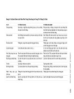
rule of thumb is to consider a project to be entirely on schedule if less
than one-third of the project buffer has been consumed. If between one-
206 Tactical Subordination in Project Management
Exhibit 8.17 Buffer Penetration Calculation
Time
Elapsed
5 days
Originally
Estimated
Duration
Currently
Estimated
Duration
Current Estimated
Buffer Penetration
(1) Task A 10 days 13 days +3 days
(2) Task B 10 days 10 days 0 days
(3) Totals 20 days 23 days +3 days
(4)
Project
Buffer
10 days
Project Buffer
Consumption
(3 days/10 days)
30%
(5)
Estimated
Delivery
30 days 30 days
5070_Pages 7/14/04 1:55 PM Page 206
third and two-thirds of the project buffer has been consumed, then the
project is reviewed and, if appropriate, plans are made to take action
when and if necessary. Projects that have penetrated into the last one-third
of the project buffer are in danger of missing their projected delivery
dates and are expedited. The report for senior management should always
contain comments as to the prognosis for projects that have penetrated
into the last third of the project buffer and may contain comments for
projects in the middle third. Exhibit 8.18 is an example of such a report
that illustrates each of the three buffer situations.
25
Project managers receive (or have on-line access to) prioritized lists
of all penetrations into buffers for their projects. These reports typically
list first the project buffers in sequence of the amount of buffer consump-
tion as a percent of the project buffer. In similar fashion, a prioritized list
of critical-chain-feeding and drum-feeding buffers showing consumption
follows. The amount of consumption as well as the amount of buffer re-
maining, the particular task that is currently active on the chain causing
the consumption, and the resource area in which the task is located are
shown for each buffer.
Each resource or department manager needs to know the relative
importance of tasks currently being worked on. Therefore, department
managers receive (or have on-line access to) a list of the tasks for their de-
partments that show all of the tasks currently being worked on and the sta-
tus of the buffers to which those tasks are connected. This report is se-
quenced in the same manner as the project manager’s report. In addition,
a department manager needs to know what work is coming to the depart-
ment in the near future and what the relative priorities of that work are.
To accommodate this need, the department manager receives a second re-
port containing similar information that shows tasks that are coming to
the department within a time frame specified by the department manager.
Critical Chain Buffer Reports 207
Exhibit 8.18 Strategic Project Status
As of September 30, 20X1
Completion
Project I D Percent Scheduled Date Project Buffer Prognosis
Broadway Plant
37%
Jul 31, 20X2 12%
Hope Product 20 %
Dec 31, 20X1
81%
Lead engineer
on leave of
absence until
12/1/20X0.
Project 3
80 %
Oct 30, 20X1
50 %
OK
5070_Pages 7/14/04 1:55 PM Page 207
Automated Buffer Management Reporting
Look again at the three projects network shown in Exhibit 8.15. Even
though the projects network illustrated is simple, it nevertheless has nine
separate buffers. Clearly, an organization that has dozens of projects, with
each project using scores of resources and having hundreds of tasks,
would find specifying and updating the interrelationships among the proj-
ects cumbersome at best and perhaps even intractable.
26
Therefore, most
organizations implementing the critical chain concept take advantage of
computer application programs that are readily available to handle these
complexities. These organizations use the buffer reporting routines and
formats available in the specific application program used.
CURRENT STATUS OF CRITICAL CHAIN
At the time of this writing, critical chain is a relatively recent development
(Critical Chain was first published in 1997)
27
and how to best interpret
buffer penetration remains controversial.
28
It is already abundantly clear,
however, that critical chain offers a powerful tool for project management.
As a new management paradigm, implementation of critical chain
requires that everyone associated with the projects have at least some fa-
miliarity with its concepts. And in order to implement critical chain as de-
scribed, it is necessary to define the project networks and resolve resource
contentions within each project.
The major effects of critical chain include the following:
• Individual projects are completed with significantly shorter dura-
tions.
• The total time needed to complete several projects is significantly
reduced.
• Promised delivery dates are met with must greater reliability.
• Capacity is freed up.
We expect the effects of critical chain to be derived from five
sources:
1. Better initial planning, particularly with respect to resource con-
tention.
2. Staggered starting of projects based on drum resource schedules.
3. Taking advantage of compensating statistical fluctuations by moving
the provision for safety time from individual tasks to the ends of
chains of tasks.
208 Tactical Subordination in Project Management
5070_Pages 7/14/04 1:55 PM Page 208
4. Taking advantage of early finishes of individual tasks.
5. Use of buffer management reports to guide tactical management ac-
tions.
Anecdotal evidence indicates that, at the present time, the benefits
of critical chain are in large part being derived only from the first two
sources.
Implementing the critical chain application apparently requires a
significantly greater level of planning than is typically being done.
29
As
projects are staggered on a drum resource, the opportunity for multitask-
ing among projects is significantly reduced. These two factors—better
planning (leading to better communication) and task focusing—account
for the reported successes with critical chain.
30
Culture Change
In addition to better planning and reduced multitasking, organizations re-
porting success in implementing the critical chain invariably mention the
need for change in the organizational culture. Such successes are typically
reported in terms of quicker and more reliable project completion as op-
posed to sustained bottom-line effect. The only cultural change that has
been accepted widely in practice is awareness by those managers involved
in the initial critical chain implementation of the damage that multitask-
ing does to schedule reliability. Managers no longer ask to see simultane-
ous progress on several projects requiring the same resource and accept
the project schedules as dictated by the drum resource. Task focusing be-
comes the norm for all employees.
The critical chain techniques described thus far require that a great
deal of attention be paid to the schedule for individual tasks. The individ-
ual task times for the project are initially estimated and planned carefully.
As the project plan is executed, data about the anticipated completion
time for each task are collected on a continuing basis. Even the notion of
taking advantage of an early finish implies that there is some measure of a
correct or right duration for each task. Since each task has an implied cor-
rect duration and sequence, a de facto schedule exists. And with the exis-
tence of a schedule, Parkinson’s Law comes into play as well.
The implication is that current implementations of critical chain are
being undertaken as local initiatives rather than as components of a larger
process of ongoing improvement. We must conclude that culture changes are
not widespread and that relatively little of the quicker and more reliable
project execution effects associated with the statistical characteristics of
project execution are being obtained in practice.
Current Status of Critical Chain 209
5070_Pages 7/14/04 1:55 PM Page 209