WIRELESS TECHNOLOGYProtocols, Standards, and Techniques pdf phần 4 pptx
Bạn đang xem bản rút gọn của tài liệu. Xem và tải ngay bản đầy đủ của tài liệu tại đây (372.53 KB, 54 trang )
P1: FDJ
book CRC-Wireless November 8, 2001 14:38 Char Count= 397
r
Location registration
r
IMSI attachment
r
IMSI detachment
Access occurs on a contention basis with the slotted ALOHA protocol as the
access algorithm. Basically, an access attempt occurs as follows. The terminal
chooses a time slot, transmits its message, and waits for an acknowledgment
for a fixed time. If no acknowledgment arrives, a random time is waited, and a
new trial is carried out. This procedure is repeated up to a maximum number
of times, as specified on the BCCH. An acknowledgment consists of sending
the following information:
r
The number of the time slot in which the access was made
r
A 5-bit codeword transmitted in the access procedure (a loop back of
the codeword)
r
The time slot number of the SDCCH
Note, from Figure 4.4, that in the access burst 68.25 of 156.25 bits are used
for guard time purposes. This is because before the initial access no infor-
mation on the terminal timing is known. Therefore, the guard time ensures
that in the initial access the information bits remain within a single time slot
upon arrival at the base station when transmitted from any part of the cell. By
determining the arrival time, the base station calculates the timing advance,
information that is sent to the terminal to be used in the subsequent transmis-
sions. The 252-µs guard time (68.25 ×3.69) due to the 68.25 bits corresponds to
a propagation distance of approximately 75 km, which, therefore, establishes
that a maximum cell radius is of 37.5 km.
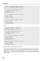
The raw access message is, in fact, embodied by only eight bits. These eight
bits are split into two fields, one containing three bits and the other containing
five bits. The three-bit field identifies the type of access (call origination, pag-
ing acknowledgment, etc.). The five-bit field contains a randomly generated
code used to distinguish the messages of two or more terminals transmitting
in the same time slot (contending for the time slot). These eight bits are CRC
encoded, which adds six parity bits to the eight bits. The resulting 14 bits
together with 4 tail bits (total of 18 bits) are half-rate convolutionally encoded
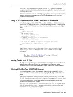
yielding data 36 bits. Figure 4.11 shows the RACH structure.
4.5.8 Stand-Alone Dedicated Control Channel
The SDCCH bears data information for signaling purposes. The SDCCH is
a two-way channel using the normal burst format. More specifically, the
SDCCH is used for signaling related to mobility management and call setup
© 2002 by CRC Press LLC
E:\Java for Engineers\VP Publication\Java for Engineers.vp
Thursday, April 25, 2002 9:27:36 AM
Color profile: Disabled
Composite Default screen
P1: FDJ
book CRC-Wireless November 8, 2001 14:38 Char Count= 397
8-bit
Raw
Message
CRC
Encoder
(+6 bits)
Convolutional
Encoder
(1/2 rate)
8
14
36
4
Tail Bits
Data Fields
FIGURE 4.11
Random-access channel structure.
management. The following tasks require the use of the SDCCH:
r
Registration
r
Authentication
r
Location updates
The use of an SDCCH usually follows that of the RACH for access purposes
and precedes the allocation of a TCH after the call setup signaling has been
completed. The SDCCH employs a set of four time slots within the 51-frame
control multiframe. Knowing that each time slot within a normal burst uses
114 bits and that the duration of a superframe is 6.12 s, the SDCCH rate is
4 × 114 × 26 ÷ 6.12 = 1937.25 bit/s. Like the TCH, the SDCCH also has associ-
ated with it an SACCH for control purposes. The same coding scheme used
for the BCCH is also used for the SDCCH, as shown in Figure 4.10.
4.5.9 Slow Associated Control Channel
The SACCH bears data information for control purposes. The SACCH is a
two-way channel using the normal burst format. A SACCH is always associ-
ated with a TCH or with an SDCCH. It uses the same carrier frequency of the
logical channel with which it is associated. The SACCH is a continuous data
channel carrying control information from the terminal to the base station,
and vice versa. In the forward link, it supports power level commands and
timing adjustments directives. In the reverse link, it conveys measurements
reports related to the signal quality of the serving base station and of the
neighboring cells.
When associated with a TCH the SACCH occurs in frames 12 or 25 of
each 26-frame traffic multiframe. It then occupies one time slot (114 bits) per
multiframe (0.120 s). Therefore, the SACCH rate is 114 ÷0.120 = 950 bit/s.
Each message comprises 456 bits, meaning that four traffic multiframes (480
ms) are used to transmit a message. When associated with an SDCCH the
SACCH occupies two time slots per control multiframe. It follows that in this
case the SACCH rate is 2 × 114 × 26 ÷6.12 = 969 bit/s.
© 2002 by CRC Press LLC
E:\Java for Engineers\VP Publication\Java for Engineers.vp
Thursday, April 25, 2002 9:27:36 AM
Color profile: Disabled
Composite Default screen
P1: FDJ
book CRC-Wireless November 8, 2001 14:38 Char Count= 397
The same coding scheme used for the BCCH is also used for the SACCH,
as shown in Figure 4.10.
4.5.10 Fast Associated Control Channel
The FACCH bears data information for signaling purposes. The FACCH is
a two-way channel using the normal burst format. It conveys messages that
must be treated in an expeditious manner and that cannot rely on the 480-ms
transmission time provided by SACCH. An example of this is the message
concerning a handover request. An FACCH empowers the characteristic of an
in-band signaling channel both for TCH and SDCCH, operating in a stealing
mode. That is, if necessary, a TCH or an SDCCH can be interrupted and re-
placed by an FACCH to transmit urgent messages. The time slot is recognized
as operating as FACCH or as TCH or SDCCH by appropriately setting the
2-bit flag field in the message of the normal burst. The same coding scheme
used for the BCCH is also used for the FACCH, as shown in Figure 4.10.
4.6 Messages
The signaling channels, with the exception of FCCH, RACH, and SCH, use the
LAPDm format to transmit information. The LAPD m protocol in the mobile
network is equivalent to the LAPD protocol in the fixed network. The mes-
sages are transmitted in segments of 184 bits. In general, the messages fit into
a single segment and, as already mentioned, the 184 bits of raw information
are processed to yield 456 bits. These 456 bits are then transmitted through
four time slots.
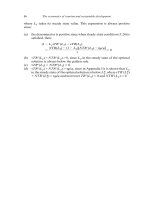
The structure of a segment is shown in Figure 4.12. Apart from the length
indicator field, which appears in every message, the presence of the other
fields will depend on the message itself. For example, there may be messages
Address
(8 bits)
Control
(8 bits)
Length
Indicator
(8 bits)
Information
(I bits)
Fill
(F bits)
184 bits
FIGURE 4.12
GSM message segment.
© 2002 by CRC Press LLC
E:\Java for Engineers\VP Publication\Java for Engineers.vp
Thursday, April 25, 2002 9:27:36 AM
Color profile: Disabled
Composite Default screen
P1: FDJ
book CRC-Wireless November 8, 2001 14:38 Char Count= 397
with zero length, in which case,with the exception of the 8-bit length indicator
field, all the other fields (176 bits) are filled with 1s.
Six of the bits in the length indicator field denote the number of octets in
the variable-length information field. Another bit in the length indicator field
determines whether ornot the current message segmentis the final segment in
the corresponding message. The address field contains the following fields:
1 bit indicating whether the message is a command or a response; 3 bits
indicating the current version of the GSM protocol; 1 bit as an extension of the
address (set to 0 in the initial version of GSM); and 3 bits indicating network
management messages or short message service messages. The control field
contains 3 bits to indicate the sequence number of the current message and
another 3 bits to indicate the sequence number of the last message received by
the entity that is sending the present message. In case the complete message
encompasses fewer than 184 bits, the fill field is stuffed with 1s.
A numberof network management messages are specified in GSM. Accord-
ing to their specific functions the messages can be of three types: supervisory
(S), unnumbered (U), and information (I). The S and U messages precede or
follow the I messages to control the flow of messages between terminals and
base stations. The I messages perform the main tasks concerning network
management. An S message may request (re)transmission or may suspend
transmission of I messages. An U message may initiate or may terminate a
transfer of I messages or may confirm a command. The S and U messages
are Layer 2 messages and, more specifically, data link control (DLC) mes-
sages. The I messages are Layer 3 messages. More specifically, they carry
out the network management operations such as radio resources manage-
ment (RRM), mobility management (MM), and call management (CM). The
RRM messages involve interactions between mobile station, base station, and
mobile switching center. The MM and CM messages use the base station as
a relay node between mobile stations and MSC where they are effectively
treated.
The next subsections summarize the main GSM messages.
4.6.1 DLC Messages
The main DLC messages and their respective purposes are listed below:
r
Set Asynchronous Balanced Mode. This is a U command message. It
initiates a transfer of I messages.
r
Disconnect. This is a U command message. It terminates a transfer of
I messages.
r
Unnumbered Acknowledgment. This is a U response message. It con-
firms a command.
© 2002 by CRC Press LLC
E:\Java for Engineers\VP Publication\Java for Engineers.vp
Thursday, April 25, 2002 9:27:36 AM
Color profile: Disabled
Composite Default screen
P1: FDJ
book CRC-Wireless November 8, 2001 14:38 Char Count= 397
r
Receive Ready. This is an S command or an S response message. It
requests transmission of an I message.
r
Receive Not Ready. This is an S command or an S response message. It
requests retransmission of an I message.
r
Reject. This is an S command or an S response message. It suspends
transmission of I messages.
4.6.2 RRM Messages
The main RRM messages and their respective purposes are listed below:
r
Sync Channel Information. This is a downlink message running on the
SCH. It conveys the base station identifier and the frame number, the
latter allowing the terminal to achieve time synchronization.
r
System Information. This is a downlink message running on the BCCH.
It contains the location area identifier,the numberof the physicalchan-
nel carrying signaling information, the parameters of the random-
access protocols, and the radio frequency carriers active in the neigh-
boring cells.
r
System Information. This is a downlinkmessage running on the SACCH.
It provides local system information to those active terminals that are
moving away from the cell where the call was originated.
r
Channel Request. This is an uplink message running on the RACH. It
is used to respond to a page, to set up a call, to update the location,
to attach the IMSI, to detach the IMSI.
r
Paging Request. This is a downlink message running on the PCH. It is
employed to set up a call to a terminal.
r
Immediate Assignment. This is a downlink message running on the
AGCH. It is utilized to assign an SDCCH to a terminal at the setup
procedure as a result of a channel request message.
r
Immediate Assignment Extended. This is a downlink message running
on the AGCH. It is utilized to assign two terminals to two different
physical channels.
r
Immediate Assignment Reject. This is a downlink message running on
the AFCH. It is utilized as a response to channel request messages
from as many as five terminals when the system is not able to provide
these terminals with dedicated channels.
r
Assignment Command. This is a downlink message running on the
SDCCH. It is used at the end of the setup call process to move the
terminal to a TCH.
© 2002 by CRC Press LLC
E:\Java for Engineers\VP Publication\Java for Engineers.vp
Thursday, April 25, 2002 9:27:36 AM
Color profile: Disabled
Composite Default screen
P1: FDJ
book CRC-Wireless November 8, 2001 14:38 Char Count= 397
r
Additional Assignment. This is downlink message running on the
FACCH. It is used to assign another TCH to a terminal already
operating on a TCH.
r
Paging Response. This is an uplink message running on the SDCCH. It
is used to respond to a page with the aim of identifying the terminal
and causing the initiation of the authentication procedure.
r
MeasurementReport. This is an uplink message running on theSACCH.
It is used to indicate the signal level of the terminal and the signal
quality of the active physical channel and of the channels of the sur-
rounding cells, for intracell or intercell handover purposes.
r
Handover Command. This is a downlink message running on the
FACCH. It is used to move a call from one physical channel to
another physical channel. It is also used for the terminal to adjust
its timing advance.
r
Handover Access. This is an uplink message running on the TCH. It
is used to provide the base station with the necessary information
so that the base can instruct the terminal on the timing adjustment
needed in a handover process.
r
Physical Information. This is a downlink message running on the
FACCH. It is used to transmit the timing adjustment the terminal
requires in a handover process.
r
Handover Complete. This is an uplink message running on the FACCH.
It is utilized after the terminal has adjusted its transmission time
within the newly assigned physical channel.
r
Ciphering Mode. This is a downlink message running on the FACCH.
It indicates whether or not user information is to be encrypted.
r
Channel Release. This is a downlink message running on the FACCH.
It informs the terminal that a given channel is to be released.
r
Frequency Redefinition. This is a downlink message running on the
SACCH as well on the FACCH. It informs the terminal about the new
hopping pattern to be used.
r
Classmark Change. This is an uplink message running on the SACCH
as well as on the FACCH. It informs the network about the terminal’s
new class of transmission power. This message occurs, for example,
when a phone is plugged in or removed from an external apparatus
with high power.
r
Channel Mode Modify. This is a downlink message running on the
FACCH. It commands the terminal to change from one channel mode
(speech or data) to another. The channel mode defines the specific
source coder (for speech) or the data speed (for data).
© 2002 by CRC Press LLC
E:\Java for Engineers\VP Publication\Java for Engineers.vp
Thursday, April 25, 2002 9:27:36 AM
Color profile: Disabled
Composite Default screen
P1: FDJ
book CRC-Wireless November 8, 2001 14:38 Char Count= 397
r
RR Status. This is a two-way message running on the FACCH as well
as on the SACCH. It reports the error conditions of the radio resource
(RR).
4.6.3 CM Messages
The main CM messages and their respective purposes are listed below:
r
Setup. This is a two-way message running on the SDCCH. It is used
to initiate a call.
r
Emergency Setup. This is an uplink message running on the SDCCH.
It is used to initiate a call.
r
Call Proceeding. This is a downlink message running on the SDCCH.
It is used as a response to a setup message.
r
Progress. This is a downlink message running on the SDCCH. It is
used to inform the calling party, through an audible tone, that the call
is being transferred to a different network (from a public to a private
one, for example).
r
Call Confirmed. This is an uplink message running on the SDCCH. It
is used as a response to a setup message.
r
Alerting. This is a two-way message running on the SDCCH. It is used
to indicate to the calling party that the called party is being alerted.
r
Connect. This is a two-way message running on the SDCCH. It is used
to indicate that the call is being accepted.
r
Start DTMF. This is an uplink message running on the FACCH. It
is used to indicate that a button ofthe phone keypad has been pressed.
This causes the network to send to the terminal a dual-tone multiple
frequency.
r
Stop DTMF. This is an uplink message running on the FACCH. It is
used to indicate that a button of the phone keypad has been released.
This causes the network to turn off a dual-tone multiple frequency.
r
Modify. This is a two-way message running on the FACCH. It is used
to indicate that the nature of the transmission is being modified (e.g.,
from speech to facsimile).
r
User Information. This is a two-way message running on the FACCH.
It is used, for example, to carry user-to-user information as part of
GSM supplementary services.
r
Disconnect/Release/Release Complete. This is a two-way message run-
ning on the FACCH. It is used to end a call. For example, if the termi-
nal is concluding a call, it sends a disconnect message to the network,
© 2002 by CRC Press LLC
E:\Java for Engineers\VP Publication\Java for Engineers.vp
Thursday, April 25, 2002 9:27:36 AM
Color profile: Disabled
Composite Default screen
P1: FDJ
book CRC-Wireless November 8, 2001 14:38 Char Count= 397
which responds with a release message, and this causes the termi-
nal to send a release complete message to the network. The same
sequence of messages flow in the opposite direction if the other party
terminates the call.
r
Disconnect. This is a two-way message running on the FACCH. It is
used to indicate that a call is terminating.
r
Release. This is a two-way message running on the FACCH. It is used
as a response to a disconnect message.
r
Release Complete. This is a two-way message running on the FACCH.
It is used as a response to a release message.
r
Status. This is a two-way message running on the FACCH. It is used
as a response to a status enquiry message to describe error conditions.
r
Status Enquiry. This is a two-way message running on the FACCH.
It causes the network element (either the terminal or the base) to
respond with a status message.
r
Congestion Control. This is a two-way message running on the FACCH.
It is used to initiate a flow control procedure, in which case the flow
of call management messages is retarded.
The CM messages occur at different stages of a call. At the beginning of a
call, the following messages run on the SDCCH:
r
Setup
r
Emergency setup
r
Call proceeding
r
Progress
r
Call confirm
r
Alerting
r
Connect
During a call, the following messages run on the FACCH of the assigned
channel:
r
Start DTMF
r
Stop DTMF
r
Modify
r
User Information
At the end of a call, the following messages run on the FACCH of the
assigned channel:
© 2002 by CRC Press LLC
E:\Java for Engineers\VP Publication\Java for Engineers.vp
Thursday, April 25, 2002 9:27:36 AM
Color profile: Disabled
Composite Default screen
P1: FDJ
book CRC-Wireless November 8, 2001 14:38 Char Count= 397
r
Disconnect
r
Release
r
Release complete
During abnormal conditions, the following messages run on the FACCH
of the assigned channel:
r
Status
r
Status enquiry
r
Congestion control
4.6.4 MM Messages
The MM messages travel on the SDCCH. The MM messages and their respec-
tive purposes are listed below.
r
Authentication Request. This is a downlink message. It is used to send
a 128-bit random number (RAND) to the terminal, which, by means
of an encryption algorithm, computes a 32-bit number to be sent to
and checked up at the base.
r
Authentication Response. This is an uplink message. It is used as a
response to an authentication request message, conveying the 32-bit
number generated out from the encryption algorithm.
r
Authentication Reject. This is a downlink message. It is used to abort
the communication between the terminal and the network as a result
of an unsuccessful authentication.
r
Identity Request. This is a downlink message. It is used to request any
of the three identifiers: IMSI (stored on the SIM), IMEI (stored in the
terminal), and TMSI (assigned by the network to a visiting terminal).
r
Identity Response. This is an uplink message. It is used as a response
to the identity request message.
r
TMSI Reallocation Command. This is a downlink message. It is used to
assign a new TMSI to the terminal.
r
Location Updating Request. This is an uplink message. It is used by the
terminal to register its location.
r
Location Updating Accept. This is a downlink message. It is used to
accept a location registration.
r
Location Updating Reject. Thisis a downlink message. It is used to reject
a location registration. A location updating may be rejected in any of
the following events: unknown subscriber, unknown location area,
roaming not allowed, or system failure.
© 2002 by CRC Press LLC
E:\Java for Engineers\VP Publication\Java for Engineers.vp
Thursday, April 25, 2002 9:27:36 AM
Color profile: Disabled
Composite Default screen
P1: FDJ
book CRC-Wireless November 8, 2001 14:38 Char Count= 397
r
IMSI Detach Indication. This is an uplink message. It is used to cancel
the terminal registration when the terminal is switched off.
r
CM Service Request. This is an uplink message. It is used to initiate
an MM operation. As a consequence, one or more MM messages will
follow.
r
CM Re-Establishment Request. This is an uplink message. It is used to
reinitiate an MM operation that has been interrupted.
r
MM Status. This is a two-way message. It is used to report error con-
ditions.
4.7 Call Management
This section outlines some call management procedures, namely, mobile ini-
tialization, location update, authentication, ciphering, mobile station termi-
nation, mobile station origination, handover, and call clearing.
4.7.1 Mobile Initialization
There are three main goals of the mobile initialization procedure:
1. Frequency synchronization
2. Timing synchronization
3. Overhead information acquisition
Frequency Synchronization. As the terminal is switched on, it scans over the
available GSM RF channels and takes several readings of their RF levels to
obtain an accurate estimate of the signal strengths. Starting with the channel
with the highest level, the terminal searches for the frequency correction burst
on the BCCH. If no frequency correction burst is detected, it then moves to
the next highest level signal and repeats the process until it is successful.
In this event, the terminal will then synchronize its local oscillator with the
frequency reference of the base station transceiver.
TimingSynchronization. After frequency synchronization has beenachieved,
the terminal will search for the synchronization burst for the timing informa-
tion present on the SCH. If it is not successful, it then moves to the next highest
level signal and repeats the process starting from the frequency synchroniza-
tion procedure until it is successful. In this event, it moves to the BCCH to
acquire overhead system information.
© 2002 by CRC Press LLC
E:\Java for Engineers\VP Publication\Java for Engineers.vp
Thursday, April 25, 2002 9:27:36 AM
Color profile: Disabled
Composite Default screen
P1: FDJ
book CRC-Wireless November 8, 2001 14:38 Char Count= 397
Overhead Information Acquisition. After timing synchronization has been
achieved, the terminal will search for overhead information on the BCCH.
If the BCCH information does not include the current BCCH number, it will
restart the mobile initialization procedure. In a successful event, the termi-
nal will have acquired, from the BCCH and through the system information
message present on the BCCH, the following main information:
r
Country code
r
Network code
r
Location area code
r
Cell identity
r
Adjacent cell list
r
BCCH location
r
Minimum received signal strength
The terminal checks if the acquired identification codes coincide with those
in the SIM card. In a successful event, it will maintain the link and monitor
the PCH. Otherwise, it will start a location update procedure.
4.7.2 Location Update
A location update procedure is carried out in one of the following events:
r
The terminal is switched on and verifies that the identification codes
present on the current BCCH do not coincide with those in the SIM
card.
r
The terminal moves into a location area different from that within
which it is currently registered.
r
There has been no activity for apreestablished amount oftime. As part
of the process used to speed the paging procedure, location reports
are used. These location reports are periodic reports used to update
the location of the terminal so that, in the event of a page, the latest
reported location is used as an initial guess to locate the terminal. The
time span between location reports constitutes a system parameter
whose value is indicated on the BCCH, varying in accordance with
the network loading.
The location update procedure starts with the uplink channel request mes-
sage on the RACH. The network answers with an immediate assignment
message on the AGCH indicating the SDCCH number to be used through-
out the location update procedure. The terminal moves to this SDCCH and
sends a location updating request message with its identification (IMSI or,
© 2002 by CRC Press LLC
E:\Java for Engineers\VP Publication\Java for Engineers.vp
Thursday, April 25, 2002 9:27:36 AM
Color profile: Disabled
Composite Default screen
P1: FDJ
book CRC-Wireless November 8, 2001 14:38 Char Count= 397
preferably, TMSI). An authentication procedure is then carried out. In case
the authentication is unsuccessful, the procedure is aborted. In a successful
event, the ciphering procedure is performed. The network then uses the lo-
cation updating accept message to assign a new TMSI to the terminal. The
terminal stores its TMSI and responds with a TMSI allocation complete mes-
sage. The location update is concluded with a channel release message from
the network to the terminal. The terminal then resumes its PCH monitoring
procedure.
4.7.3 Authentication
An authentication procedure may be required at the location update pro-
cedure or at the request of a new service. The authentication procedure
starts with the network sending an authentication request message to the
terminal; the message conveys a 128-bit random number (RAND). The ter-
minal uses the RAND, the secret key, Ki, stored at SIM, and the encryp-
tion algorithm, referred to as A3, to compute a 32-bit number, referred to
as a signed response (SRES). Another 64-bit key, the ciphering key, Kc, is
computed using another encryption algorithm, referred to as A8. The Kc
parameter is later used in the ciphering procedure. After these computa-
tions, the terminal responds with an authentication response message, which
contains the SRES. The network uses the same parameters and the same
algorithm to compute another SRES. The terminal SRES and the network
SRES are then compared with each other. If a match occurs, the network ac-
cepts the user as an authorized subscriber. Otherwise, the authentication is
rejected.
4.7.4 Ciphering
Ciphering (or encryption) is usually required for user transactions over the RF
link after authentication has been successful. The network transmits a cipher-
ing mode message to the terminal indicating whether or not encryption is to
be applied. In case ciphering is to be performed, the secret key Kc (64 bits),
which was generated previously in the authentication procedure, the frame
number (22 bits), and an encryption algorithm, referred to as A5, are used
to compute a 114-bit encryption mask. This mask is modulo-2 added to the
2 × 57 = 114 bits of the data fields, in the bursts. Deciphering is obtained at
the base station by performing the same procedure. The terminal answers
with a ciphering mode acknowledgment message. Note that the ciphering
to be used is continuously changing (on a frame-by-frame basis), because it
depends on the current frame number.
© 2002 by CRC Press LLC
E:\Java for Engineers\VP Publication\Java for Engineers.vp
Thursday, April 25, 2002 9:27:36 AM
Color profile: Disabled
Composite Default screen
P1: FDJ
book CRC-Wireless November 8, 2001 14:38 Char Count= 397
4.7.5 Mobile Station Termination
After the mobile initialization procedure, the terminal camps on the PCH. It
eventually detects a paging request message conveying its TMSI. This impels
the terminal to access the RACH to transmit a channel request message. An
immediate assignment with the SDCCH number is sent by the network on the
AGCH. The terminalmoves to SDCCH andthe following occurs. Theterminal
transmits a paging response message indicating the reason for the specific
message (response to a paging). An authentication procedure is carried out,
as already described. In a successful event, a ciphering procedure is accom-
plished, as already described. The base station then sends a setup message.
The terminal responds with a call confirmed message followed by an alerting
message toindicate that the subscriber is being alerted. Atthe subscriber’s call
acceptance, the terminal sends a connect message and removes the alerting
tone. The network responds with an assignment command message indicat-
ing the traffic channel number to be used for the conversation. The subscriber,
still on the SDCCH, responds with an assignment acknowledgment message
and moves to thetraffic channelthat has been assigned. The network confirms
the acceptance of the call by the other party by means of a connect acknowl-
edgment message on the FACCH of the assigned TCH. And the conversation
proceeds on the TCH.
4.7.6 Mobile Station Origination
The terminal detects a user-originated call. It then accesses the RACH to
send a channel request message. An immediate assignment with the SDCCH
number is sent by the network on the AGCH. The terminal moves to this
channel and the following occurs. The terminal transmits a paging response
message indicating the reason for the specific message (call setup). The base
station responds withan unnumbered acknowledgment message. An authen-
tication procedure is carried out, as already described. In a successful event,
a ciphering procedure is performed, as already described. The terminal then
sends a setup message. The base station responds with a call confirmed mes-
sage followed by an alerting message in which case the terminal applies the
ring-back tone. At the called party’s call acceptance, the network sends an as-
signment command message informing the traffic channel number to be used
for the conversation. The subscriber, still on the SDCCH, responds with an
assignment acknowledgment message and moves to the traffic channel that
has been assigned. The network confirms the acceptance of the call by the
other party by means of a connect acknowledgment message on the FACCH
of the assigned TCH. And the conversation proceeds on the TCH.
© 2002 by CRC Press LLC
E:\Java for Engineers\VP Publication\Java for Engineers.vp
Thursday, April 25, 2002 9:27:36 AM
Color profile: Disabled
Composite Default screen
P1: FDJ
book CRC-Wireless November 8, 2001 14:38 Char Count= 397
4.7.7 Handover
The handover processin a GSM networkhas the mobile terminalas anintegral
part of the procedure. The whole process is named mobile-assisted handover
(MAHO). While making use of the traffic channel, the mobile monitors the
signal levels of its own channel, of the other channels of the same cell, and
of the channels of six surrounding cells. The measurements are then reported
to the base on an SACCH. Concerning the control of the process, handovers
may occur:
r
Within the same BTS or between BTSs controlled by the same BSC
r
Between different BSCs controlled by the same MSC
r
Between different BSCs controlled by different MSCs
r
Between different BSCs controlled by different MSCs belonging to
different PLMNs
In addition, there are two modes of handovers: synchronous or asynchro-
nous. In the synchronous mode, the origin cell and the destination cell are
synchronized. By measuring the time difference betweentheir respective time
slots, the mobile itself may compute the timing advance. This is used to adjust
its transmissions on the new channel, therefore, speeding up the handover
process. In the asynchronous mode, the origin cell and the destination cell
are unsynchronized. The timing advance, in this case, must be acquired by
means of a procedure involving the terminal and the new BTS, as follows. The
mobile terminal sends a series of access bursts with a zero timing advance
through several handover access messages. The BTS then computes the re-
quired timing advance using a round-trip time delay of the messages. On the
average, the handover processing time in the synchronous mode (200 ms) is
twice as long as that of the synchronous mode (100 ms).
Next a simple asynchronous handover procedure occurring between BTSs
of the same BSC is described. While in conversation on a TCH, the terminal
monitors the signal levels of several channels. These measurements are re-
ported to the base station on a periodic basis by means of the measurement
report message running on the SACCH. Whenever suitable, the base sends a
handover command message on the FACCH, indicating that a handover is to
take place. The number of the new TCH is included within the message. The
terminal thenmoves to this new channel and sends aseries of handover access
messages so that the base may compute the timing advance to be transmitted
to the terminal. This is done in the physical information message transmitted
to the terminal on the FACCH. The timing adjustment is carried out and the
terminal responds with a handover complete message.
© 2002 by CRC Press LLC
E:\Java for Engineers\VP Publication\Java for Engineers.vp
Thursday, April 25, 2002 9:27:36 AM
Color profile: Disabled
Composite Default screen
P1: FDJ
book CRC-Wireless November 8, 2001 14:38 Char Count= 397
4.7.8 Call Clearing
The call clearing process may be initiated either by the network or by the
mobile. In either case, the channel used for the exchange of information is the
BCCH. Assuming the network initiates the clearing, the base sends a discon-
nect message to the terminal. The terminal responds with a release message.
The base replies with a release complete message. If the terminal initiates the
clearing, then the same messages flow, but in the opposite direction.
4.8 Frequency Hopping
GSM cellular reuse planning is given an additional level of sophistication
by the introduction of frequency hopping (FH). In FH, the signal in a given
time slot moves from one frequency to another according to a preestablished
hopping pattern. By changing frequencies periodically, the transmission be-
comes less vulnerable to fading, because the probability of encountering more
than one faded frequency at the same time diminishes with the increase of
the number of frequencies utilized. Therefore, the signal is affected by fading
only during part of its time. Besides, FH may reduce co-channel interference
if co-cells are assigned different hopping patterns.
As opposed to fast FH, in which the change of frequency (or frequencies)
occurs during the symbol time, GSM uses slow FH with the hopping tak-
ing place at each TDMA frame (one hopping at each 4.615 ms). The FH faci-
lity is implemented in all GSM terminals. The application of FH, however, is
decided by the network operator. The hopping algorithm is based on such
parameters as the set of hopping frequencies, the hopping pattern, frame
number, and others, which are transmitted over the SCH. There are two pos-
sible FH operation modes: cyclic and random. In the cyclic mode, the hopping
occurs sequentially over the set of frequencies. In the random mode, the hop-
ping is performed in a pseudorandom fashion according to one out of 63
allowable patterns. Furthermore, the FH facility may be implemented at the
baseband or at the RF levels. The baseband FH implementation makes use
of a number of transceivers, each of which operates on a fixed frequency. In
this case, the FH occurs as the baseband information moves from one input of
one transceiver to the input of another transceiver, according to the preestab-
lished hopping sequence. The RF FH implementation provides the FH at
the frequency synthesizer level for a given transceiver. In this case, the FH
occurs as the synthesizer changes its frequency in accordance with the given
hopping pattern.
© 2002 by CRC Press LLC
E:\Java for Engineers\VP Publication\Java for Engineers.vp
Thursday, April 25, 2002 9:27:36 AM
Color profile: Disabled
Composite Default screen
P1: FDJ
book CRC-Wireless November 8, 2001 14:38 Char Count= 397
All carriers in the GSM band, with the exception of the standard broadcast
carriers, are entitled to hop. The standard broadcast carrier, also known as
the base channel, contains the FCCH, the SCH, and the BCCH, and is the
beacon upon which the terminals carry out their measurements and extract
the necessary information. All signals within a cell and also within a group
of cells hop in a coordinated manner. In other words, the hopping sequences
are chosen so that frequency overlapping is avoided (the hopping sequences
are orthogonal to each other). Both the uplink and the downlink operate with
the same FH sequence.
When a terminal is to use FH, it is informed about the available set of
hopping channels and the hopping sequence number.
4.9 Discontinuous Transmission
GSM equipment is designed for discontinuous transmission (DTx), a feature
utilized to conserve battery power and to reduce interference. DTx takes ad-
vantage ofthe fact that in a normal conversation,on average, the voice activity
factor is far less than 100% (typically less than 60%). Therefore, in theory, the
transmitter must be on only during the time the voice is effectively active,
and off otherwise.
To implement this feature, the terminal is equipped with a voice activity de-
tector (VAD). Upon detecting voice (in the presence of noise)or noise, the VAD
outputs a corresponding signal that controls a transmitter switch. Therefore,
the design of such a VAD plays a decisive role in transmission performance. A
decision in favor of a wrong detection will certainly produce annoying effects
in the transmission. In such a case, a clipping effect in speech may be noticed.
Note that, as the transmitter is switched off between talkspurts, at the receiv-
ing end the background acoustic noise present in the conversation abruptly
disappears. It has been observed that this can be annoying to the listener. To
minimize the effect of such a noise “modulation,” a synthetic signal, known
as comfort noise signal (CNS), with characteristics matching those of the back-
ground noise, is introduced at the receiver. Note that the background noise
thus generated is notstandard noise. It triesto conformwith thecharacteristics
of the background noise of the current transmission. To accomplish this, the
noise parameters are computed at the transmit end during a time span of four
frames after the VAD detects the end of a talkspurt. It is very unlikely that the
speech restarts during this time, so that the noise is present for the parameter
evaluation. These parameters are sent to recompose the noise at the receiver.
Besides VAD and CNS functions, another function of the DTx feature is
speech frame extrapolation (SFE). The SFE aims to replace a speech frame
© 2002 by CRC Press LLC
E:\Java for Engineers\VP Publication\Java for Engineers.vp
Thursday, April 25, 2002 9:27:36 AM
Color profile: Disabled
Composite Default screen
P1: FDJ
book CRC-Wireless November 8, 2001 14:38 Char Count= 397
badly corrupted by error with a preceding uncorrupted speech frame. This
replacement is basedon the fact that consecutive speech frames are highly cor-
related. Therefore, the use of SFE improves the signal quality or, equivalently,
allows for a reduced carrier-to-interference ratio.
4.10 Power Control
GSM employs power control techniques to adjust the power of both mo-
bile stations and base stations for better performance. Power control reduces
co-channel interference and increases battery life. Mobile stations can have
their poweradjusted in steps of 2dB with the power levels ranging over 30 dB,
i.e., 16 power levels are permitted. The time span between power adjustments
is 60 ms, corresponding to 13 frames. Base stations can also control their own
power, this process involving the mobile station: the mobile station monitors
the signal received from the base station and the base station transmitting
power can be changed to improve the signal reception at the mobile station.
4.11 Spectral Efficiency
GSM uses powerful interference counteraction techniques such as adaptive
equalization, powerful error-correcting codes, efficient modulation, speech
frame extrapolation, and others. These render GSM system robust and ca-
pable of operating at a low carrier-to-interference ratio, in which case, reuse
factors of three or four cells per cluster, depending on the environment, are
admissible.
A number of spectral efficiency definitions are available. In accord with
Reference 12, the spectral efficiency parameter η is defined as
η = conversations/cell/spectrum
The number of physical channels in the 50-MHz GSM spectrum is 124 carriers
× 8 channels/carrier = 992 (GSM-900). It can also be assumed that all these
992 channels can be used for conversation. Therefore, for a reuse factor of 4:
η =
992
4 × 50
=4.96
© 2002 by CRC Press LLC
E:\Java for Engineers\VP Publication\Java for Engineers.vp
Thursday, April 25, 2002 9:27:36 AM
Color profile: Disabled
Composite Default screen
P1: FDJ
book CRC-Wireless November 8, 2001 14:38 Char Count= 397
And for a reuse factor of 3:
η =
992
3 × 50
=6.61
The same calculations can be performed for the other GSM systems. The
results will be very close to these.
4.12 Summary
GSM has emerged as a digital solution to the incompatible analog air inter-
faces of the differing cellular networks operating in Europe. Among the set of
ambitious targets to bepursued, full roaming was indeed a veryimportant one.
In addition, a large number of open interfaces have been specified within the
GSM architecture. Open interfaces favor market competition with operators
able to choose equipment from different vendors. GSM was the first system to
stimulate the incorporation of the personal communication services philosophy
into a cellular network. These and other innovative features rendered GSM
networks, either in the original GSM conception or as an evolution of it, a very
successful project with worldwide acceptance. GSM systems are found oper-
ating in frequency bands around 900 MHz (GSM-900), 1.8 GHz (GSM-1800),
or 1.9 GHz (GSM-1900). A new revision of the GSM specifications define an E-
GSM that extends the original GSM-900 operation band and stipulates lower
power terminals and smaller serving areas.
References
1. Eberspaecher, J., Bettstetter, C., and Vhogel, H J., GSM: Switching, Services and
Protocols, John Wiley & Sons, New York, 2001.
2. Tisal, J., The GSM Network: The GPRS Evolution: One Step Towards UMTS, John
Wiley & Sons, New York, 2001.
3. Steele, R., Gould, P., and Chun, L. C., GSM, cdmaOne and 3G Systems, John Wiley
& Sons, New York, 2000.
4. Nielsen, T. and Wigard, J., Performance Enhancements in a Frequency Hopping GSM
Network, Kluwer Academic Publishers, Dordrecht, the Netherlands, 2000.
5. Heine, G. and Horrer, M., GSM Networks: Protocols,Terminology,and Implementation,
Artech House, Norwood, MA, 1999.
© 2002 by CRC Press LLC
E:\Java for Engineers\VP Publication\Java for Engineers.vp
Thursday, April 25, 2002 9:27:36 AM
Color profile: Disabled
Composite Default screen
P1: FDJ
book CRC-Wireless November 8, 2001 14:38 Char Count= 397
6. Zvonar, Z., Jung, P., and Kammerlander, K., GSM: Evolution towards 3rd Generation
Systems, Kluwer Academic Publishers, Dordrecht, the Netherlands, 1999.
7. Garg, V. K. and Wilkes, J. E., Principles and Applications of GSM, Prentice-Hall,
Englewood Cliffs, NJ, 1998.
8. Redl, S., Weber, M., and Oliphant, M., GSM and Personal Communications Handbook,
Artech House, Atlanta, 1998.
9. Levine, R. and Harte, L., GSM Superphones: Technologies and Services, McGraw-Hill
Professional, New York, 1998.
10. Lamb, G., Lamb, B., and Batteau, Y., GSM Made Simple, Cordero Co., 1997.
11. Mehrotra, A. K., GSM System Engineering, Artech House, Atlanta, 1997.
12. Goodman, D. J., Wireless Personal Communications Systems, Addison-Wesley Long-
man, Reading, MA, 1997.
13. Tisal, J., GSM Cellular Radio, John Wiley & Sons, New York, 1996.
14. Redl, S., Weber, M., and Oliphant, M., An Introduction to GSM, Artech House,
Atlanta, 1998.
15. Mouly, M. and Pautet, M B., The GSM System for Mobile Communications, Telecom
Publishing, Palaiseau, France, 1992.
© 2002 by CRC Press LLC
E:\Java for Engineers\VP Publication\Java for Engineers.vp
Thursday, April 25, 2002 9:27:36 AM
Color profile: Disabled
Composite Default screen
P1: FDJ
book CRC-Wireless November 8, 2001 16:35 Char Count= 327
5
cdmaOne
5.1 Introduction
The need for increased capacity was the great motivation for the advent of
American digital cellular technology. As demand for wireless services in-
creased, mainly in dense urban areas, the old analog standard, known as
AMPS (Advance Mobile Phone Service), proved inadequate to satisfy the de-
mand. Time Division Multiple Access technology, based on the EIA/TIA/IS-
54 specifications (later on enhanced and renamed EIA/TIA/IS-136) was the
first solution to the capacity problem of the old analog system. By offering
roughly a threefold increase in capacity by dividing each 30 kHz AMPS chan-
nel into three time slots, this system was the first American response to the
European cellular second generation, the GSM.
This digital novelty, however, was not enough to soothe a number of ser-
vice providers, who argued that such a technology would not be adequate
for future growth in service. Other alternatives were then considered, and
a technical committee was formed to study and generate cellular standards
for wideband services. In the late 1980s and early 1990s, QUALCOMM, Inc.
of San Diego proposed a Code Division Multiple Access, CDMA, system
and together with Pacific Telesis demonstrated its operation. Extensive suc-
cessful field trials and network refinement led the Telecommunication
Industry Association (TIA) and the Electronic Industry Association (EIA) to
adopt QUALCOMM system as their interim standard, the “TIA/EIA/IS-95—
Mobile Station–Base Station Compatibility Standard for Dual-Mode Wide-
band Spread Spectrum Cellular System.”
[2, 3]
The TIA/EIA/IS-95 specifications establish that the system operate on a
dual-mode (analog and digital) basis, both modes within the same frequency
band. The dual-mode capability facilitates the transition from the analog en-
vironment to a digital environment. Although compatible, analog and digital
© 2002 by CRC Press LLC
E:\Java for Engineers\VP Publication\Java for Engineers.vp
Thursday, April 25, 2002 9:27:36 AM
Color profile: Disabled
Composite Default screen
P1: FDJ
book CRC-Wireless November 8, 2001 16:35 Char Count= 327
systems are rather different; details of the digital system are the subject of this
chapter. TIA/EIA/IS-95 supports a direct sequence spread spectrum techno-
logy with 1.25 MHz band duplex channels. Therefore, an operating company
that chooses this CDMA technology must deactivate about 42 contiguous
30-kHz channels of its analog system. Coexistence of analog and digital sys-
tems implies that dual-mode mobile stations are able to place and receive
calls in any system and, conversely, all systems are able to place and receive
calls from any mobile station. Handoff operations in such a scenario require
some attention. A mobile station may initiate a call in the CDMA system and,
while the call is still in progress, it may migrate to the analog system, if re-
quired. The search for one or another system for the initial registration is not
specified by the standard and the exact action is dependent on the manufac-
turer. In fact, the standard leaves a number of issues to be detailed by the
manufacturer. Those recommendations in the standard appearing with the
verbal forms “shall” and “shall not” identify the requirements from which
no deviation is permitted. Those with “should” and “should not” indicate
that several possibilities are permitted. There are still others with “may”
and “need not” and “can” and “cannot,” which are certainly much less re-
strictive. Therefore, solutions may be implemented differently by different
manufacturers.
A number of innovations have been introduced in the CDMA system as
compared with earlier cellular systems. Soft handoff is certainly a great nov-
elty. In soft handoff, handoff from one base station to another occurs in a
smooth manner. In soft handoff, the mobile station keeps its radio link with
the original base station and establishes a connection with one or more base
stations. The excess connections are given up only when and if the new link
has sufficient quality. Another innovation introduced in the CDMA system is
the use of Global Positioning System (GPS) receivers at the base stations. GPSs
are utilized so that base stations be synchronized, a feature vital to the soft
handoff operation. Vocoders at variable rates are specified to accommodate
different voice activities aimed at controlling interference levels, thence in-
creasing system capacity. Sophisticated power control mechanisms are used
so that the full benefit of spread spectrum technique is realized.
The first CDMA systems were employed under the TIA/EIA/IS-95A speci-
fications. The A version of the specifications evolved to TIA/EIA/IS-95B, in
which new features related to higher data rate transmission, soft handoff
algorithms, and power control techniques have been introduced. The name
cdmaOne isthen used to identify the CDMA technology operating with either
specification.
This chapterdescribes the cdmaOne specifications. Mostof the descriptions
concern TIA/EIA/IS-95A specifications. A final section describes the new
features included in TIA/EIA/IS-95B.
© 2002 by CRC Press LLC
E:\Java for Engineers\VP Publication\Java for Engineers.vp
Thursday, April 25, 2002 9:27:36 AM
Color profile: Disabled
Composite Default screen
P1: FDJ
book CRC-Wireless November 8, 2001 16:35 Char Count= 327
5.2 Features and Services
TIA/EIA/IS-95 specifications establish two types of features: voice features
and short message service features.
5.2.1 Voice Features
The following are the primary voice features.
r
Call Delivery (CD). CD allows the reception of a call while in a roaming
condition.
r
Call Forwarding Busy (CFB)/Call Forwarding Busy No Answer (CFNA)/
Call Forwarding Busy Unconditional (CFU). CFB, CFNA, and CFU
allow a called subscriber to have the system send incoming calls,
addressed to the called subscriber’s directory number, to another di-
rectory number (forward-to number), or to the called subscriber’s
designated voice mailbox. This happens when the subscriber is en-
gaged in a call or service (for CFB active), or when the subscriber
does not respond to paging, does not answer the call within a spec-
ified period after being alerted, or is otherwise inaccessible (CNFA
active). The inaccessibility may be characterized by the following: no
paging response, unknown subscriber’s location, inactive subscriber,
CD not active for a roaming subscriber, Do Not Disturb active, etc. If
CFU is active, calls are forwarded regardless of the condition of the
termination.
r
Call Transfer (CT). CT enables the subscriber to transfer an in-progress
established call to a third party. The call to be transferred may be an
incoming or outgoing call.
r
Call Waiting(CW). CW providesnotification to a controlling subscriber
of an incoming call while the subscriber’s call is in the two-way state.
Subsequently, the controlling subscriber can either answer or ignore
the incoming call. If the controlling subscriber answers the second
call, it may alternate between the two calls.
r
Calling Number Identification Presentation (CNIP)/Calling Number Iden-
tification Presentation Restriction (CNIR). CNIP provides and CNIR
restricts the number identification of the calling party to the called
subscriber. Thetermination networkreceives the calling numberiden-
tification (CNI) as part of the basic call setup. This CNI may in-
clude one or two calling parties numbers (CPNs), a calling party
© 2002 by CRC Press LLC
E:\Java for Engineers\VP Publication\Java for Engineers.vp
Thursday, April 25, 2002 9:27:36 AM
Color profile: Disabled
Composite Default screen
P1: FDJ
book CRC-Wireless November 8, 2001 16:35 Char Count= 327
subaddress (CPS), redirecting numbers (RNs), and a redirecting sub-
address (RS).
r
Conference Calling (CC). CC provides a subscriber with the ability to
conduct a multiconnection call, i.e., a simultaneous communication
between three or more parties (conferees). If any of the conferees to a
conference call disconnects, the remaining parties remain connected
until the controlling subscriber disconnects.
r
Do Not Disturb (DND). DND prevents a called subscriber from re-
ceiving calls. When this feature is active, no incoming calls shall be
offered to the subscriber. DND also blocksother types of alerting, such
as the CFU abbreviated (or reminder) alerting and message waiting
notification alerting. DND makes the subscriber inaccessible for call
delivery.
r
Flexible Alerting (FA). FA causes a call to a pilot directory number to
branch the call into several legs to alert several termination addresses
simultaneously. The first leg to be answered is connected to the calling
party and the other call legs are abandoned.
r
Message Waiting Notification (MWN). MWN informs enrolled sub-
scribers when a voice message is available for retrieval. MWN may
use pip tone or alert pip tone to inform a subscriber of an unretrieved
voice message(s).
r
Mobile Access Hunting (MAH). MAH causes a call to a pilot directory
number to search a list of termination addresses for one that is idle
and able to be alerted, in a way that only one termination address is
alerted at a time.
r
Password Call Acceptance (PCA). PCA is a call-screening feature that
allows a subscriber to limit incoming calls to only those calling parties
who are able to provide a valid PCA password (i.e., a series of digits).
r
Preferred Language (PL). PL provides the subscriber with the ability to
specify the language for network services.
r
Priority Access and Channel Assignment (PACA). PACA allows a sub-
scriber to have priority access to voice or traffic channels on call origi-
nation by queuing these subscribers’ originating calls when channels
are not available. The subscriber is assigned one of several priority
levels and theinvocation ofPACA isdetermined tooneof two options:
permanent, in which the feature is always available, and demand, in
which the feature is available only on request.
r
Remote Feature Control (RFC). RFC allows a calling party to call a
special RFC directory number to specify one or more feature
operations.
© 2002 by CRC Press LLC
E:\Java for Engineers\VP Publication\Java for Engineers.vp
Thursday, April 25, 2002 9:27:36 AM
Color profile: Disabled
Composite Default screen
P1: FDJ
book CRC-Wireless November 8, 2001 16:35 Char Count= 327
r
Selective Call Acceptance (SCA). SCA is a call-screening service that al-
lows a subscriber to receive calls only from parties whose CNPs are
in an SCA screening list of specified CNPs.
r
Subscriber PIN Access (SPINA). SPINA allows subscribers to control
whether their mobile station is allowed to access the network. This
feature may be used by subscribers to prevent unauthorized use of
their own mobile station or fraudulent use by a clone.
r
Subscriber PIN Intercept (SPINI). SPINI enables subscribers to restrict
outgoing calls originated from their mobile station. The subscriber
requires a SPINI PIN authorization code to originate calls meeting
specified criteria (e.g., international call type). SPINI PIN shall not be
required on unrestricted call types (e.g., emergency) and may not be
required for a list of frequently called numbers, regardless of their call
type.
r
Three-Way Calling (3WC). 3WC provides the subscriber with the abil-
ity to add a third party to an established two-party call, so that all
three parties may communicate in a three-way call.
r
Voice Message Retrieval (VMR). VMR permits a subscriber to retrieve
messages from a voice message system (VMS).
r
Voice Privacy (VP). VP provides a degree of privacy for the subscriber
over the base station to mobile station (BS–MS) radio link.
5.2.2 Short Message Service Features
The following are the primary short message service features:
r
Short Message Delivery–Point-to-Point Bearer Service (SMD-PP). SMD-
PP provides bearer servicemechanisms for delivering ashort message
as a packet of data between two service users, known as short mess-
age entities (SMEs). The length of the bearer data may be up to 200
octets. Implementations and service providers may further restrict
this length. The SMD-PP service attempts to deliver a message to an
MS-based SME whenever the MS is registered even when the MS is
engaged in a voice or data call.
r
Cellular Paging Teleservice (CPT). CPT conveys short textual messages
(up to 63 characters) to an SME for display or storage.
r
Cellular MessagingTeleservice (CMT). CMTconveys and manages short
messages to an SME for display or storage. This teleservice should
coordinate the use of the display and arbitrate between conflicting
users or services. Each message includes attributes for management
of the messages received by the SME.
© 2002 by CRC Press LLC
E:\Java for Engineers\VP Publication\Java for Engineers.vp
Thursday, April 25, 2002 9:27:36 AM
Color profile: Disabled
Composite Default screen
P1: FDJ
book CRC-Wireless November 8, 2001 16:35 Char Count= 327
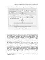
5.3 Architecture
The TIA/EIA/IS-95 system uses the ANSI/TIA/EIA-41 (or ANSI-41, for
short) platform, which is basically built on the TIA/EIA/IS-41-C (or IS-41-C,
for short) specifications with some minor protocol changes. The main ele-
ments constituting the ANSI-41 network reference model is depicted in
Figure 5.1. The model shows the functional entities and interface points be-
tween these entities. These entities or physical interfaces do not necessarily
imply a physical implementation. In fact, more than one functional entity can
be implemented on a single physical device. In such a case, the internal inter-
faces between these functional entities need not comply with the standards.
The entities and interfaces shown in Figure 5.1 are described next.
5.3.1 Mobile Station
The mobile station terminates the radio path on the user side of the network
enabling the user to gain access to services from the network. It incorporates
user interface functions, radio functions, and control functions, with the most
BS
MS
BTS BSC
MSC EIR
MSC
DMH
VLR
PSPDN
ISDN
PSTN
IWFOS
PLMN
VLRHLRAC
SME
MCMCSME
M
M
M
H
DG
N
C
B
Pi
Mi
Di
Ai
A
L
O
I
F
E
Abis
Um
Q
FIGURE 5.1
ANSI-41 network reference model.
© 2002 by CRC Press LLC
E:\Java for Engineers\VP Publication\Java for Engineers.vp
Thursday, April 25, 2002 9:27:36 AM
Color profile: Disabled
Composite Default screen