business modeling with uml business patterns at work phần 9 pdf
Bạn đang xem bản rút gọn của tài liệu. Xem và tải ngay bản đầy đủ của tài liệu tại đây (657.49 KB, 28 trang )
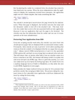
Figure 10.4: Top-level diagram of the logical view, showing the packages and their
dependencies in the system. This is a class diagram, which shows only packages (UML does
not have a specific diagram for packages).
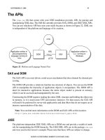
Figure 10.5: A deployment diagram showing the physical structure of the hardware nodes
and their connections. The top uses standard UML symbols; the others have special icons for
the different node stereotypes. A tool should be able to switch between both of these
representations.
Figure 10.4 shows the top-level diagram for the logical view with a number of packages
and their dependencies to each other. In contrast, Figure 10.5 shows the deployment
view of the system, with the nodes (computers and devices) in the system and their
connections to each other. It is also possible to show the executable components
allocated to each of the nodes by drawing components inside the nodes, but that hasn’t
been done in this example. The figure shows the same diagram twice: in the top figure,
the diagram uses standard UML symbols; in the bottom figure, the diagram uses special
icons attached to the different stereotypes, such as PC, Printer, and Server. None of
these stereotypes is standard in UML, but all can be used to get special icons for the
different node types, thus making the deployment diagram more like a “normal” system
diagram that has been hand-drawn with a drawing tool. The second picture uses the
correct set of stereotypes and thus adheres to the UML specification.
Using the Business Architecture to Define the Software
Architecture
Transferring the information in the business model to the software model is not a simple
or automatic process. Unfortunately, there isn’t a one-to-one mapping for this process,
and there is no simple algorithm to translate the business model into a software model.
They are two different models, with different purposes. The business model describes a
business or a specific part of a business, and not all parts of the business transfer into
the software systems (for example, the people, manual activities, and many business
goals). Nor can the classes and objects in the business model be directly converted into
corresponding software classes and objects; doing so often leads to a very confusing
software architecture where things that can’t or shouldn’t go into the software system
becomes classes and objects in the system.
When a business model is created with the explicit and exclusive purpose of finding
requirements and working as the basis for a software model, it is important not to over-
model, by which we mean describe things that are of no relevance to the software
model. Numerous interactions and discussions about all aspects of the business are
important, but they need to be described in a way that directly addresses the software
requirements. It is more fruitful to concentrate on the business concepts that do carry
through smoothly to software. Naturally, if the purpose of the business model is broader
(e.g., to document the business or to identify innovations in the business), more work
has to be put into the business model.
With all that in mind, the software developer has to critically view and evaluate the
information in the business model in order to decide which parts of the model are
relevant to the software system being developed and to determine how that information
is best represented in software classes. Connections between the two architectures can
be made and conclusions can be drawn when defining a software architecture based on
the business architecture. Figure 10.6 is a process diagram of the business and software
development processes, as well as the connections and the resources used or produced
in the processes. Although this figure presents an overview rather than a detailed
description, it serves to illustrate the complexity and the many activities and resources
involved in these two processes.
Figure 10.6: A process diagram showing an overview of the business modeling and the
information system development process.
The ultimate goal is of course to create the software system(s) that best support and fit
the business; therefore, the business model is a very important foundation both for
specifying the requirements and for designing the software. The business model is used
in software modeling to:
Identify the information systems that best support the operation of the business.
The systems can be new, standard, or legacy.
Find functional requirements. The business model is used as a basis for identifying
the correct set of functions or use cases that the system should supply to the business
processes.
Find nonfunctional requirements. These requirements, such as robustness, security,
availability, and performance, typically span and involve the entire system.
Act as a basis for analysis and design of the system. For example, information about
resources in the business model can be used to identify classes in the system. However,
it is not possible to directly transfer the classes in the business model to the software
model.
Identify suitable components. Modern software development makes use of
components, which are autonomous packages of functionality that are not specific to a
certain system but can be used in several systems. Most component technology has
concentrated on technical components, but increasingly, there is interest in defining
business components that encapsulate a specific and reusable area of business
functionality. Business models are a good way to identify these areas of functionality and
to define the appropriate set of services.
The next sections explore these uses in more detail.
Identify the Information Systems
A very basic use of the business model is to identify the most suitable information
systems for the business, that is, which systems are necessary and suitable to enable
and run the processes? Often, such decisions regarding which information systems are
needed are made ad hoc or are based on the type of systems that are traditionally
required in this type of business. Critically reviewing the needs of the business and the
current system topology will often pinpoint ways to improve the support for the business.
Not all systems in the business will need to be newly developed. In fact, an important
goal is usually to minimize the amount of new development because of the high cost
involved.
There are three systems in a business:
New. Systems specifically developed to support this business. They are developed from
scratch and are optimized to support the processes.
Standard. Systems sold by third-party suppliers. Typical offerings in this category are
accounting, workflow, and personnel administration systems. Though standard systems
are often cheaper to buy than to develop, keep in mind the services in these systems are
generic and not always optimized to the specific business.
Legacy. Existing systems that are in use in the business. These represent a previous
investment and should be incorporated in the new solution if possible. In many cases,
the legacy systems can be adapted or extended to include new services that better
support the business.
Rarely, when deciding which systems are needed, can the “ideal” solution—one in which
totally new and highly adapted and optimized systems have been created—be used.
More likely, some of the legacy system must be used or enhanced, even if a new system
has clear advantages in terms of functionality. In some cases, a standard system may be
cheaper than developing a new system in-house or through subcontractors. Economical
considerations are always an important factor in choosing the new system topology.
Replacing systems requires a replacement and phase-out plan. This plan describes how
the new system will replace the old systems and how the information in the old system
will be transferred to the new system. Typically, this plan requires a phase during which
both systems run in parallel, so that if the new system fails, the old system can be
reverted to.
The process and the assembly line diagrams in the business model are used to develop
the correct system topology. These diagrams help the architect to identify activities that
require services from an information system. Though it’s not important to see the
services defined in detail at this point, it is important to identify the information systems
that are required by or that are of use to the processes.
Activities in the business processes that indicate the use of services from information
systems are typically:
Information storage, retrieval, organization, and administration. Information is used
as an asset to the business processes. Much of the information stored will be about
other objects in the business process, such as process state, instructions, or facts about
resources and business events.
Processing, conversion, and presentation. Stored information must be processed
(e.g., summarized), converted into different formats, or presented in various pedagogical
ways.
Knowledge and decision making. When so-called intelligent software can draw
conclusions or make decisions from the information. It implies that the software system
refines and enhances the information.
Communication. Whenever information, events, or instructions need to be sent from
one location to another.
Control of hardware. Whenever hardware resources, such as machines, need to be
controlled and monitored.
Today, many businesses would be impossible to run without the support of information
technology. Systems that contain online business-to-business commerce, just-in-time
delivery, workflow support, high distribution, shopping on the Internet, or finance
information cannot be visualized without high-level software systems. Unfortunately,
identifying exactly which systems are needed and what functionality should go into each
system is not easy to define or describe in a simple process. The architect must balance
the functionality in legacy systems, the functionality that can be bought in standard
systems, and the functionality that is unique or specific enough to the business in
question that makes the development of a new system worthwhile or necessary.
Technical constraints, such as the environments in which the legacy systems operate,
may also be a factor in deciding between what can be bought or developed.
Using the assembly line diagram as described earlier would result in a list of the services
needed by the processes, but it then would have to be compared to the current system
configuration and weighed against the cost constraint. Instead, to identify a suitable
strategy for the systems, a system topology diagram, illustrated in Figure 10.7, is used. A
system topology diagram is a class diagram with packages and dependencies between
the packages. Each package, stereotyped to «system» (using standard UML), denotes a
system in this business. The systems can be either legacy, standard, or planned.
Characteristics for each system are documented as properties for each system package.
By iterating and trying out different possibilities in such a system topology diagram, the
final system topology is slowly discovered. There are many things to consider, such as
estimating the cost for each new system or defining the order in which existing systems
will be replaced. (These considerations are beyond the scope of this book.)
Figure 10.7: A system topology diagram showing the support systems for a business.
Find Functional Requirements
Perhaps the most important use of the business model in the context of software
engineering is as the basis for identifying the functional requirements of a system, that is,
the functions or use cases that the system should provide.
Functional requirements of the system are described in use cases, textual descriptions of
the sequence of interactions between an information system and an external actor (the
actor can be either the role of a person or of another system). A use case discusses
each step of the communication between the system and its surroundings. Actually, this
text description specifies the functional requirements, not the UML use-case diagram,
which is only an overview of the actors and the use cases present in the system. A use-
case description concentrates on functional requirements, but sometimes also contains
nonfunctional requirements specific to the use case in question (e.g., such as
performance issues). Actors in the use-case model are typically resources in the
process, such as people or machines.
A use case is not equivalent to a process. A use case provides a service that is required
as part of a process outside the system. A use case is fully implemented in software,
whereas a process is normally only partly implemented in software (the term use case is
an abstraction to define communication between actors and a system). Use cases can
be considered as the specification of the services the software system provides to the
business process.
The use cases are identified through a use-case analysis as part of the requirements
analysis activity of the software development process. The use-case analysis uses parts
of the business model to find the required services that the information system should
provide (and that the business needs). Resources (people, machines, or other systems)
in the business become actors to the analyzed system, and the interaction of these
resources in the activities are captured in terms of use cases. A resource is considered
an actor only in terms of a specific system and from the system architect’s viewpoint, so
there is no change to the business model.
The assembly line diagram is a powerful tool for identifying the required use cases for
the system. It depicts the necessary references from activities in a process to packages
of objects in an information system. A package of objects (represented by a package
stereotyped to «assembly line») could represent an entire information system, a
subsystem or component in an information system, or even a specific class of objects.
The first iteration of analysis usually begins with references to systems (each assembly
line is a system) and is then repeated with a special assembly line diagram for each
system, where the packages represent logical subsystems in that system. Naturally, if
the purpose of the business model is to find the requirements for a specific system, you
begin directly with the assembly line diagram for that system. The subsystems packages
are identified by looking at the resource and information models in the business model to
find suitable and logical divisions of functionality that should be part of the system in
question.
When an assembly line diagram has been completed on the subsystem level for a
specific system, it may be necessary to revisit, refine, and detail the assembly line
diagrams in the business model. When analyzing the process from the viewpoint of a
specific system, these questions may arise: What needs to be clarified in order to specify
the system in detail? What requests are met by the process to the information system
that enable and support the process? The references from the processes or activities to
the assembly line packages are communication requests between resources (actors) in
the process to the information system. A sequence of such references becomes a use
case in the system.
The integration point between the business process and the use case is the assembly
line diagram. The use case should not be defined by collecting references from the
process to an assembly line and labeling them a use case. The use case must be a
complete functionality, from its initiation by an actor to the return of a result from the
system. When using the business model to define the use cases, you must look from
both the view of the business process (asking what is needed from the information
system?) and from the view of the system (asking what will make up a complete and
well-defined use case?). Otherwise, you might end up with rather poor, ill-formed, and
partial use cases.
The business model can also be used to identify the suitable incremental steps in an
iterative development cycle; it can aid in defining which use cases are most important for
the processes (while technological considerations define which use cases carry the most
risk or cover the architecture of the system, two other means of defining the suitable
incremental steps).
Figure 10.8 shows an assembly diagram and its references to different information
systems. References can be linked to define a use case according to the guidelines for a
use case. For each of the information systems, a use-case model can be created (see
Figure 10.9) that defines the use cases in more detail.
Figure 10.8: A business process uses services from different information systems. (Note: the
use-case ellipses are not part of the diagram—they are only an illustration in this figure.)
Figure 10.9: A use-case diagram as seen from the order system.
In Figures 10.8 and 10.9, communication between the systems has not been defined.
One could imagine that, for example, the accountant only works with the accounting
system. The accounting system then retrieves the order information from the sales
system as part of registering a transaction. In that case, the reference in Figure 10.8
from the registering transaction process should go to the accounting system. The
accounting system then becomes an actor to the sales system in Figure 10.9.
A part of the software design that is indirectly affected by the functional requirements is
the graphical user interface, the GUI. The GUI can be designed at an early stage of
development, after the actors and the use cases in the system have been defined, and
often leads to the development of a prototype. The prototype can then be put in the
hands of real-life users early, for their feedback. The user-interface design uses the actor
definition as well as both the functional and nonfunctional requirements as its basis. The
user interface is implemented by boundary objects that handle the presentation,
navigation, and communication of information between the actors (a boundary object is,
for example, what a window object in the user interface represents). These boundary
objects will have relationships to other objects that represent the communicated
information. The detailed collaboration between the boundary objects and the other
objects are later designed in detail and documented in interaction diagrams, such as
sequence or collaboration diagrams in UML.
Find Nonfunctional Requirements
Nonfunctional requirements, such as performance, availability, and security, are not
normally connected to a specific use case or functionality; instead, they are usually
generic properties that affect and must be maintained and handled in many use-cases.
Often the nonfunctional requirements aren’t even specific to a certain system but are
applicable to the enterprise level, that is, all the systems in a business. These
requirements normally are not designed or implemented in a specific component or
subsystem, but affect many or all components and subsystems. The process diagrams
and descriptions in the business model are studied to identify nonfunctional
requirements. Nonfunctional requirements are identified by looking at the following needs
in the business processes:
§ Lead times (the time between an order and a delivered product)
§ Response time
§ Business process performance tracking
§ Quality measurements
§ Availability
§ Resource consumption
§ Security
Values for these nonfunctional requirements may not be specified in the process
diagram, in which case they are specified in the requirements activity of the software
development process. Specifications that typically indicate the affect of nonfunctional
requirements on the entire software system also reside in the goal models, another part
of the business model that affects the nonfunctional requirements.
It is a good idea to illustrate the functional requirements (like use cases) and the
nonfunctional requirements together at an early stage in a matrix, as shown in Figure
10.10. The matrix can list those nonfunctional requirements that affect a specific function
(an X indicates a connection) or can contain specific values for the nonfunctional
requirement. The measurement of each value depends on the properties of each
nonfunctional requirement; for example, performance is typically a time value, whereas
security might be a level value. This relatively simple tool illustrates that nonfunctional
requirements typically span more than one function, and often more than system; that is,
nonfunctional requirements are often at the enterprise level.
Figure 10.10: A matrix cross-referencing functional and nonfunctional requirements.
The matrix clearly visualizes that the nonfunctional requirements normally are not
connected to a specific use case, but span several functions. It is important to describe
both the functional and nonfunctional requirements at the system and the subsystem
levels. The requirements are documented in a requirements specification that includes
the use-case specification. The requirement specification is the contract between the
customer or user and the development organization that is responsible for developing
the correct system.
Act as Basis for Analysis and Design
Even though there is no one-to-one correlation between the business model and the
software model, a lot in the business model can be used in the analysis and design of
the software. Tasks such as identifying classes, their attributes and operations, their
structures and relationships, and collaborations between objects of classes can be
carried over to the software model. Since the software system handles and supports the
business, many of the classes in the business model will be reflected and implemented
in software. That said, it’s still important to look at the business model from the viewpoint
of each system and to identify which classes are actually required in each system.
Process and assembly line diagrams can indicate software classes. Resources that are
used in the diagrams are sometimes represented in software; and a process can also be
represented in software as a process supporting object, an object that runs or tracks the
execution of the process. A process supporting object holds the order of activities and
the state of the process and coordinates the resources involved in the process. To
clarify: The process supporting object is not the process, it is a software object that
supports and coordinates the support of the process. Some of the resources involved in
the process are not implemented in software but are communicated with, through the
interface of the system. For example, people outside of the system would not be
depicted in the software system; but, from the systems point of view, they would be seen
as actors that use use cases in the system. The objects in the system that handle
communication with actors are referred to as boundary objects.
The process and assembly line diagrams also define collaborations between objects;
answering, how do the objects collaborate to perform a specific service (use case)?
These collaborations are also part of the software design, since they describe software
objects that perform operations on each other or communicate with actors outside the
system. The objects involved in a collaboration can be categorized as active, reactive, or
passive. An active object runs independently of other objects and initiates collaborations
itself, for example at specific points in time. A reactive object reacts to specific events
(implemented as business event objects) or needs to be triggered in order to start a
collaboration. A passive object never initiates a collaboration; it only delivers information
and executes when called upon by other objects. Process supporting objects are either
active or reactive. Passive objects are often referred to as entity objects (objects holding
information that are typically stored in a database). Process supporting objects cannot be
passive, since they execute and represent the process.
Many of the concepts and relationships defined in the conceptual model that was defined
in the business vision will be entity objects. The resource diagrams (including information
and organization diagrams) that are part of the business structural view are also a good
basis for identifying entity objects since information and state of resources are stored in
an information system.
The meta-model in Figure 10.11 is an overview of the mapping of the business model
concepts and their information system concepts. The implementation classes, shown in
the upper right of the diagram, are process supporting objects, entity objects, boundary
objects, and business event objects. All these classes refer to actual software classes
that are implemented in the software system. The process supporting classes implement
support for the business processes in the business model and obtain information from
the process diagrams and descriptions (the processes are not shown in the meta-
model).
Figure 10.11: A meta-model showing categories of specification classes in the business
model and categories of implementation classes in the software model.
The entity classes implement and map to the information objects in the business model.
An information object will contain information about other concepts in the business
model: An information object can contain information about a person or a physical
product in the business or about an abstract resource such as an order, or about another
information object, or hold information about a process (holding the state of the process).
It is the information about these concepts that is implemented to the information system;
the actual resources cannot usually be implemented in software. Separating the object
itself from the information about it in the business model is not always done; this is, in
our experience one of the reasons that translating business models into information
systems has proven to be so difficult. The event classes implement the business events
from the business model, and represent events that typically trigger the start of a process
or decide the next state of a process. The process supporting classes, the entity classes,
and the event classes are all seen as business object classes, since they all represent
business concepts.
The boundary classes implement the interface to the system, that is, the system’s
interaction with other resources in the overall process. The boundary object classes are
more technically oriented, and implement interfaces such as user interfaces, interfaces
to other systems, or interfaces to hardware devices (e.g., that control or instruct a
machine). Boundary classes are part of the technical design of the information system
and thus are not considered business objects. There are also other technical classes in
the information system architecture, such as classes for handling a specific database
product, a class library abstracting a specific operating system, or classes for connecting
different information systems together.
One important area comprises business rules, which are scattered throughout the
business models and affect all types of implementation classes. Guidelines for
implementing the different types of rules mentioned in Chapter 5, “Business Rules,” are:
Invariants. Implemented in the class to which the invariant refers.
Pre- and postconditions. Implemented in the operation of the class to which the
conditions refer (precondition tested before and postcondition after).
Derivational and computational constraints. Implemented in the class that makes the
derivation, computation, or conclusion.
Relationship constraints. Implemented in the class that creates or administrates the
structure (or possibly in both classes if a relationship is administered in more than one
class).
Guards. Implemented in a process supporting class, where the guard condition is used
to decide which and when the next activity of the process should be performed.
Identify Suitable Components
Component-based development has almost replaced object-oriented development as the
programming paradigm of today. A number of competing component models have
emerged: Microsoft’s COM+, Sun’s Enterprise JavaBeans, and CORBA. Component-
based development is, however, a continuation of object-oriented development, and the
two go very well together.
Component-based development has arisen from the realization that reusing object-
oriented systems at the source code level is very difficult, and that the reuse of software
requires a common infrastructure so that different components can be exposed to one
another and cooperate. Software solutions must adapt as the business adapts, and to do
that, software must be as technically neutral as possible. A key to achieving that
neutrality is to reuse business components based on one of the common component
models. The most successful business components are those that can be “rewired” in
many configurations in effective response to business change.
A component can be defined as:
[A]n executable unit of code that provides physical black-box encapsulation of related
services. Its services can only be accessed through a consistent, published interface that
includes an interaction standard [Ambler 98]
[5]
A component exposes properties, methods, and events through an interface standard
(such as COM+, CORBA, or JavaBeans) that makes the component configurable and
that enables the component to cooperate with other components about which it
previously had no knowledge. A component also exposes its interface through meta-
data, data that at runtime describes the properties and behavior of the component.
As component-based development becomes more popular, and the components
become more business-oriented rather than technically oriented, the business model will
be capable of being used to identify the components in a software system. The goal for
identifying and defining components is to find the correct set of services for each
component, so that the component becomes autonomous and can be reused in more
than one system (i.e., it can be configured or adapted to a certain degree for each
system). A component is configurable through its exposed properties so that, for
example, a process supporting object in a system can configure a component to suit its
specific needs. To date, techniques for identifying suitable business components have
been desperately lacking, and this activity is still an area under research.
In software architecture, a component is defined in its own package, which supplies a
number of services. A component package has a connection to both the logical view of
the software architecture, in that it implements a specific part of the functionality in the
logical view, and to the component view, in terms of a physical component that is
deployed on one or more computers. The idea is that the functionality of the component
package is reusable and that the component package can be allocated and deployed in
several nodes in the hardware architecture (which in turn deploys the process and
deployment views in the software architecture). Here, the hardware architecture can
refer to either a system or, more so, the architecture on an enterprise level (all of the
systems in the business).
The assembly line diagram from the business model can be used to identify
components, similar to the process of identifying systems or subsystems. The assembly
line packages then represent a specific component. Finding the appropriate level of
functionality for a component (i.e., assembly line package) is an iterative task for which
the designer will have to experiment with different levels of abstraction. When the
services of an assembly line package defined at the component level can be used by
more than one process, the appropriate component level has been identified. The
services are identified as references from the process to the assembly line package. This
process is similar to trying to identify subsystems through assembly line diagrams, but
with the added requirement that the services be generic and reusable by more than one
application and more than one business process. The difference between trying to
identify components with the assembly line diagram and studying use-cases in several
systems is that the former is done by identifying commonality among business process
and the latter is done by finding similarities in the information systems. The techniques
are not necessarily exclusive; they can be used together.
The component package contains classes that implement the services of the
components, but it presents a single component interface to its users (users in this
context are other classes or components in a system). Depending on the component
model, there may also be technical requirements for defining the component package.
Most of the component models allow the definition of events, so that a component can
generate events to other components that notify them about important situations. In the
case of a business component, such an event is a business event. Often, component
technology is used to encapsulate legacy applications, in which case, the component
designer has to look at the services available from the legacy system as well as the
services desired by the business processes. The component then must handle
conversions or additional functionality that can adapt the services of the legacy system to
better work with the current business processes.
Another special case is when a component is designed without the requirements for a
specific system. Instead, a business domain model is defined that models a generic
domain. This model is used to define generic components for this domain. Examples of
domains are financial price, accounting, or network administration services. Designing
domain-based components has proven difficult, because software development often
requires the real-life test of a specific system to determine whether the component really
works (both technically and in terms of the functionality offered). Some early initiatives in
this area are IBM’s San Francisco project and Microsoft’s BizTalk framework.
The relationship between a business process, use case, and component can be
summarized in this way: A business process will use one or more use cases that a
system supplies, and the use cases can be internally implemented through generic
components that supply all or part of the use cases. Figure 10.12 illustrates this
relationship.
Figure 10.12: A process uses the use cases an information system supplies. The use cases
are implemented by components in the information system.
[5]
[Ambler 98] Ambler, Scott W. Process Patterns: Delivering Large-Scale Systems Using
Object Technology. New York: Cambridge University Press, 1998.
Summary
A software architecture describes the key mechanisms of a system (or systems), along
with their relationships and collaborations. Architectural design is not concerned with
code design, nor is it dependent on features of a programming language. It is the base
design of the overall system or of a suite of systems in the enterprise. Even though
interface standards, such as CORBA or COM+, exist and can serve as a base
technology for the architecture of a system, they don’t replace the need to define an
architecture for the system or for the business as a whole.
A number of characteristics or properties of an architecture must be prioritized and
weighed against each other. Functional characteristics include the functionality of the
system; nonfunctional characteristics are properties such as performance, security,
usability, and availability. The development characteristics, such as modifiability,
portability, reusability, and the amount of reuse, integrateability, and testability, are not
visible at runtime but are increasingly important to consider. The economic
characteristics, such as time to produce the system, cost, and lifetime of the system, are
also aspects for the architect to consider before making architectural decisions. It is
impossible to achieve maximum benefit from all of these characteristics because they
are in conflict with each other; therefore, tradeoffs have to be made.
The software architecture is organized in five views, as defined by Philippe Kruchten
[Kruchten 95]
[6]
: a use-case view to capture the functional requirements; a logical view to
capture the high-level subsystem and conceptual design; a deployment view to define
the physical structure of hardware nodes; an implementation view to specify the structure
of the code; and the process view to capture parallel execution and its synchronization.
The knowledge and information in a business architecture is used to define the software
architecture. This isn’t a one-to-one mapping, and there is no simple algorithm to convert
the business model into a software model. They are two different models that serve
different purposes. The business model describes a business or a specific part of a
business; not all of the business goes into the software systems. To define a software
architecture, the business architecture is used to:
§ Identify suitable support systems.
§ Identify functional requirements.
§ Identify nonfunctional requirements.
§ Act as basis for analysis and design.
§ Identify suitable components.
Creating a business model before the software models, then using the information in that
business model for the creation of software models, will increase the quality of the
software systems. Systems that better support the business of which they are a part will
be the result.
The next chapter gives a practical example of a business model that is created and then
used as the basis for a software model.
[6]
[Kruchten 95] Kruchten, Philippe. The 4+1 View Model of Architecture. Piscataway, NJ:
IEEE Software, November 1995.
Chapter 11: A Business Model Example
Overview
Chapters 3 and 4 presented the steps for business modeling. Recall that business
modeling begins with expressing the visions and goals of the business, and defining the
business terminology. After the visions, goals, and terminology are clearly defined and
understood, the business processes, organization, resources, and rules can be modeled.
During the business modeling process, supporting systems may be created, removed, or
changed. The last step is to evaluate and adjust the project results.
This chapter applies these steps and the patterns described in Chapters 6 through 9 to
model an example mail order firm that has to migrate into the new world of e-business
and network economy. This example is based on our experience in modeling these types
of projects. The company is fictitious, but the business structure is based on existing
businesses.
Bob’s Mail Order
Bob’s Mail Order, established in 1983, sells office equipment, such as copy and fax
machines, switchboards, mobile phones, computers, software, and other office supplies
to larger companies. Under its trademark, Top, the company sells products purchased
from subcontractors or products it manufactures itself. Conducting business in this way
allows Bob’s Mail Order to be independent of anyone else’s trademark, branding, and
marketing. Bob’s management also realized that by advertising and attempting to sell a
new product before manufacturing it, they could reduce the capital investment.
In recent years, the means of doing business has changed, and Internet-based mail
order firms have become a serious threat to Bob’s Mail Order, whose internal systems
are old and inefficient, and can’t meet the demands of the changing business
environment. In addition, the new Internet-based firms have lower sell expenses
because of smart Internet solutions, enabling them to offer lower prices and to invest
more money in marketing, thereby increasing their marketing shares. This business
model example uses the concepts previously discussed in Chapters 1 through 10 to
demonstrate how Bob’s Mail Order can overcome these strategic business problems and
update its support systems accordingly. The four views introduced in Chapter 4,
“Business Views,” are the basis for the analysis:
§ Business Vision
§ Business Structure
§ Business Behavior
§ Business Process
Because the views are different aspects of the business and not separate diagrams, one
view at one time may be considered, while several views are considered simultaneously
at another.
The intent of this business model example is to demonstrate business modeling and
specify requirements of software systems, rather than actually build software systems.
The result of the business model in this case study is a requirement specification that will
serve as the input for building supporting software systems. From that point, numerous
methods can be used to build the software systems, such as Rational Unified Process,
OMT, Fusion, Catalyst, or Select Perspective.
Visions and Goals
The Business Vision view of a business contains the business idea and its goals
expressed in a vision statement and a goal model. Because it is difficult to formulate a
vision statement and goals without defining the key concepts, a conceptual model can be
created in parallel to complement this view, to help clarify the key concepts of the
business.
The vision statement for Bob’s Mail Order is:
We should be the leading supplier of office equipment and supplies. We should offer
customers attractive solutions and good value for their money. By not going through a
retailer, we cut the sales expenses. Integrating our sales processes with our customers’
purchase processes results in highly efficient communication and delivery. To be able to
integrate these processes, we must provide several interfaces, such as Internet, e-mail,
FTP, telephone, and fax. We can integrate further by offering additional services such as
inventory tracking and automatic purchasing.
Goal Model
The goal of Bob’s Mail Order is to increase its market share from 15 percent to 55
percent in a 24-month period. This is achievable by satisfying its customers, having a
highly motivated staff, conducting 5,000 transactions per day, and earning a high profit
from those transactions. However, increasing the current number of transactions, 1,000,
to 5,000 will not be easy. To do this, Bob’s Mail Order has to increase both the number
of regular telephone customers as well as Internet customers. To realize the increase in
Internet customers, Bob’s Mail Order home page must be easy to find, and its visitors
must be encouraged to register. Therefore, registration must be made clearly beneficial
to these visitors, or they won’t register. Bob’s Mail Order must offer something in return
for registering, such as a discount off the first order. But increasing the number of visitors
and making it beneficial to register is an expensive undertaking for Bob’s, and can
impact the profit in negative terms. On the other hand, making these investments in the
home page is necessary to achieve an increase in the number of market shares and
ensure a high profit in the future. These goals are marked as contradictory.
The goal of high profit is hindered by that fact that Bob’s Mail Order has too much
restricted equity. The amount of restricted equity is caused by inefficient production and
purchasing, as well as inaccurate predictions about the incoming orders. In addition, the
product lines do not always meet the customers’ needs; clearly, market analysis and
product development have a high potential for improvement. Some of the problems in
production, product development, and market analysis stem from confusion about
terminology. For example, the marketing department refers to new product sets as “new
products,” whereas to the production department, the term “new products” means
variations on items. Other problems stem from system issues. For example, the legacy
sales systems cannot be connected directly to the Internet; many manual steps are
required for each sale or transaction on the home page.
The goals for Bob’s Mail Order are diagrammed in the goal model shown in Figure 11.1.
It carries out the vision by directly relating concrete goals to the business and its
processes. The objective of the goal model is to serve as a starting point for setting up a
project that implements the vision; in this case, turning Bob’s Mail Order firm into the
leading supplier of office equipment and supplies.
Figure 11.1: Goal model for Bob’s Mail Order firm.
Conceptual Model
The conceptual model that complements the goal model for Bob’s Mail Order firm is
shown in Figure 11.2. This model defines the key concepts that are important for
modeling this business.
Figure 11.2: Conceptual model describing the key concepts of Bob’s Mail Order firm.
The business plan is one of the key concepts in Bob’s Mail Order firm. It consists of the
marketing plan, product strategy, Internet strategy, and the business ideas. It should
result in high profit. The conceptual model also indicates that the marketing plan that is a
part of the business plan also influences the business plan. The vision statement that is
manifested in the goal model motivates the business idea.
The product strategy is another key concept in Bob’s Mail Order firm. It develops the
supplier that manufactures and delivers items. The product strategy also results in
production facilities, products, and product sets. The product strategy is based on the
market analysis and is also a part of the business plan.
The product sets describe the products. Examples of product sets include printers,
copying machines, and handbooks. The products are concepts for the actual items. For
example, the product printer HP/5000 (which belongs to the product set printers) is the
concept or term that encompasses all actual HP/5000 printers. Typical product attributes
are description, design reference, and version number. The items are the actual printers,
and they have attributes such as a serial number and age.
Implementing the market plan leads to an increased number of market shares.
Customers place orders and pay via transactions, which leads to more market shares.
An order results in a manufactured and delivered item. The delivered items satisfy a
customer’s demand. The delivery process is controlled via key ratios, such as optimum
delivery times or quality requirements.
Business Processes
The Business Process view focuses on how to carry out the vision and goals outlined in
the vision statement, goal model, and conceptual model. The process diagram, shown in
Figure 11.3, is used to model the business processes for Bob’s Mail Order 24 months
from now. Each process is allocated the specific goal that it must achieve. In addition,
the processes can also indicate the steps necessary for improving a business or the
supporting systems.
Figure 11.3: Bob’s Mail Order processes.
The market development process of Bob’s Mail Order takes a market analysis as input
and delivers a marketing plan as output. The goal of the market development process is
to increase the number of market shares. The marketing plan, which is also a part of the
whole business plan, controls the process of business development. The goal of the
business development process is to achieve an increase in transactions and high profit,
which would aid in achieving the overall goal of an increase to 55 percent of market
share. The business development process is responsible for developing the business
and its strategies, to meet the demands of the market. It delivers a business plan, which
is, according to the conceptual model, composed of a market plan, a product strategy, an
Internet strategy, and a business idea. In addition to the business plan, the business
development process follows the plan itself. For example, the business development
process is responsible for developing Bob’s Mail Order home page, a critical aspect
because it is one of the resources that will be used to increase the number of
transactions.
The business plan controls the management process, product development process,
production development process, and subcontractor development process. The
management process aims to achieve the goal of satisfying customers and motivating
staff. It also defines key ratios that control the delivery process. The product
development process supplies the delivery process with products that meet the
customers’ expectations. The production development process aims to increase the
efficiency of production; it also supplies the delivery process with production facilities.
The subcontractor development process is responsible for the subcontractors’ delivery
processes. This process ensures that the subcontractors deliver the specified items on
time.
The delivery process takes a customer’s order as input and delivers an item to that
customer. The goal of the delivery process is timely delivery. The process is controlled
by the key ratio defined in the management process. When an order is placed, it should
be filled as soon as possible. The customer should make payment before delivery. It is
also important to reduce inventory, because maintaining too many items in stock is
expensive. This means that Bob’s staff must be able to accurately predict the number of
incoming orders and plan production and purchase based on that prediction. Later on in
this case study this process is further decomposed and detailed.
The business processes for Bob’s Mail Order were modeled with the Process Control
Layer pattern and the Process Supply Layer pattern, discussed in Chapter 9, “Process
Patterns.” These powerful patterns are often used together to facilitate the structuring of
most businesses.
Resources and Organization
Resources and organizations are modeled in the Business Structure view. Organization
models show the structure of the human resources, and the resource models show both
structure and behavior of other resources, such as products, documents, and machines.
The resources in the resource model are mainly those used in the process model. The
conceptual model describing the overall concepts for Bob’s Mail Order will help us to
explore the resource model and, later, the organization.
Resource Modeling
Order and item are two of the key concepts in the conceptual model for Bob’s Mail Order
(Figure 11.2) that are used in the process model in Figure 11.3. The behavior of the
order resource is modeled in Figure 11.4. An order has three states: placed, not paid,
and not suspended. An order can be paid and filled, but during that time it can also be
suspended for a period or it can be canceled. There are several situations in which
orders might be canceled, for instance, when an order is placed but the customer does
not pay, or when it is impossible to deliver for some reason (trade embargo,
bankruptcies, etc.). Production stoppages and credit risks are two other factors that
might cause an order to be canceled. A cancelation is normally temporary and resolved
when the cause is handled.
Figure 11.4: Order statechart.
Figure 11.5 models the behavior of an item resource. An item can be proposed, then
enter the Started state, where it moves from the manufacturing state to manufactured.
The manufactured item can then be delivered. At any point, the item also can be
suspended for a period of time, or canceled if the movement from proposed item to
delivered item is stopped.
Figure 11.5: Item statechart.
Figure 11.6 shows the item and order resources and their organization in relation to
additional resources, such as product, production facilities, supplier, key ratio, and
product set. The item resource is described with a serial number and a placement. The
Placement, Site, and Geographical Location classes are structured according to the
Geographical Location pattern, discussed in Chapter 7, “Resource and Rule Patterns.”
Production facilities are those necessary to produce the items. The Supplier delivers
items; it can be a subcontractor or an internal production department. Key Ratio controls
restrict equity, delivery time, the optimum time for introduction of new products, and error
rate in production. Product is the concept for Item; it can be an object, such as the Nokia
mobile phone 6150, while the items are the actual phones, with a serial number.
Figure 11.6: Resource model for Bob’s Mail Order.
The product sets are used to organize and group the products. For example, writing
tables, desk lamps, chairs, bookshelves, file cabinets, and wastebaskets can be
organized by grouping them as office furniture. Office furniture can be subject to certain
sales campaigns and package solutions; and the office furniture department is staffed
with skilled people.
The Product Data Management pattern discussed in Chapter 7, “Resource and Rule
Patterns,” was used to structure the products and the product sets shown in Figure 11.6.
The description attribute, in the Product Connection Specification class, can have values
such as parts, refill, or refinement. For example, Bob’s Mail Order product set
Switchboard Solution can either be the product Office 2000 or the product Small
Switchboard Solution. Both products contain other products, including the actual
switchboard, computers, fax machines, software, and headsets. The relationship
between these two products and their parts is captured by the class Product
Connections, and is specified by the class Product Connection Specification. The class
Product Set Rule is used to specify that product sets can be connected to each other; for
example, the product set Switchboard Solution can consist of Computers, which is also a
product set in itself.
Resource models are complemented with business rules. One such rule might be a
restriction on a customer’s credit rating, or the relationship between incoming orders and
production rate. Some of these rules, credit rating for example, are candidates for Fuzzy
Business Rules. Other rules, especially constraints, are candidates for OCL. The
following OCL rule is a business rule that specifies (constrains) that the number of
placed orders should be equal to the number of manufactured items.
context order:
self->select( state = #placed )->size =
product.item->select( state = #manufactured )->size
Organizational Modeling
The Business Structure view also includes the organizational aspects of Bob’s Mail
Order firm. The structure of an organization is important to understand not only for
restructuring purposes, but also for clarifying the responsibilities of each organizational
unit. The object diagram in Figure 11.7 aims to clarify the structure of the organizational
units in Bob’s Mail Order firm. This diagram is based on the Organization and Party
pattern, discussed in Chapter 7, “Resource and Rule Patterns.”
Figure 11.7: Bob’s Mail Order organization.
Bob’s Mail Order has a Board composed of the president and other shareholders. There
are seven departments at Bob’s Mail order firm and one of them, the Sales Department,
consists of two additional departments—Telesales and Web sales. Bob’s Mail Order
includes the following organizational units:
§ The Financial Department is responsible for the firm’s finances, including
credit references, credit card checks, and accounts receivable.
§ The Production Department produces items, either by assembling items that
they manufacture or by relabeling items purchased from subcontractors.
§ The Purchase Department works with purchasing outside products and
developing subcontractor relationships.
§ The System Department is responsible for the technical infrastructure and
information technology of the business. It comprises system analysts,
programmers, system architects, operators, and support staff.
§ The Sales Department, which is divided into Telesales and Web Sales, is
responsible for selling products.
§ The Product Department develops new products and product sets.
§ The Marketing Department is responsible for marketing and implementing
the marketing plan.
The next subsection shows how the organizational units interact with each other and
how responsibility for each of them can be established.
Interaction Analysis
The Business Behavior view uses interaction analysis to allocate responsibility to
organizational units and the business processes that intersect with them. Interaction
analysis is performed simultaneously with organizational modeling and business process
modeling. Sequence diagrams are used to show the interactions between organizational
units as well as the processes that take place within or cross each organizational unit.
An interaction is a sequence or a scenario that begins with a business event, such as a
question or an order, and ends with a result. For example, Bob’s Mail Order accepts
credit card orders from customers. Assume that prior marketing and telemarketing have
resulted in an inquiry from a customer to the Sales Department. The customer wants to
know if a particular item is available and the cost of the item. The customer might also try
to negotiate for a better price. If the customer is satisfied with the offer for the item, he or
she places an order, pays for it, and receives the ordered item. The Financial
Department is responsible for processing the payment, in this case a credit card
transaction. The Production Department is responsible for taking the order and delivering
the item. The sequence of events for this interaction is shown in Figure 11.8. The
organizational units in the figure are picked up from the object diagram in Figure 11.7.
Figure 11.8 is based on the Action Workflow pattern discussed in Chapter 9, “Process
Patterns,” which is a useful pattern for modeling interactions.
Figure 11.8: Credit card order interaction analysis, based on the Action Workflow pattern.
Figure 11.9 is the sequence diagram for an interaction analysis for purchasing. The
Purchase Department is responsible for purchasing items. It must confer with other
organizational units in order to determine what to purchase, when to make the purchase,
and the quantity to purchase. The first step is to ask the Sales and Marketing
Departments for prognosis to determine whether there is a demand for the product, and,
if so, how much of a demand. The Purchase Department then asks the Production
Department about the stock figures, that is, how much of the product in question is in
stock. The Financial Department supplies information regarding the liquidity. Once this
information is received, the Purchase Department begins negotiations with the Supplier,
which should result in the purchase of items. The model shown in Figure 11.9 is also
based on the Action Workflow pattern described in Chapter 9, “Process Patterns.”
Figure 11.9: Purchase interaction analysis based on the Action Workflow pattern.
The credit card order scenario in Figure 11.8 is an instance of the order process, which
is a subprocess to the delivery process (illustrated in Figure 11.3). The order process is
responsible for the result: delivering the ordered and paid item. The Sales Department is
responsible for conducting the actual sale of the item; the Production Department is
responsible for providing the correct stock figures and for delivering on time; and the
Financial Department is responsible for checking the credit card transactions.
Process Decomposition
Complex processes can be decomposed to enable better understanding. For example,
the delivery process in Bob’s Mail Order is a complex process that can be decomposed
using the overall process diagram in Figure 11.3, the sequence diagrams in Figures 11.8
and 11.9, and Time-to-Customer Process pattern discussed in Chapter 9, “Process
Patterns.” The result is three subprocesses:
§ Order
§ Procurement
§ Customer interaction
Figure 11.10 shows the decomposed delivery process.
Figure 11.10: The decomposed delivery process.
The order process is responsible for on-time delivery, invoice and credit card payments,
and customer satisfaction. The process is triggered by a placed order and ends with a
delivered item and a satisfied buyer. The order process is controlled by key ratios
(discussed previously in the “Resource Modeling” section), items, and products. The
order process is primarily executed in the Sales and Financial Departments, but it also
may involve the procurement process—if, for example, the supply of items is affected.
The procurement process is responsible for delivering items on time to the order process
and for satisfying customers. This process is triggered by market and sales prognosis. It
then purchases, refines, and sometimes manufactures items, and finally delivers them to
the order process. The key ratios that control the efficiency of this process are defined in
terms of quality and stock figures. The procurement process involves all organizational
units, including the subcontractors and suppliers. The customers are not involved in the
procurement process.
The customer interaction process is responsible for taking many orders. It is supplied
with customer information, item information, and product information. This interaction
takes place via Bob’s Mail Order home page, telephone, e-mail, or fax.
The assembly line diagram shown in Figure 11.11 is used to further clarify the delivery
process. This diagram visually depicts the synchronization, interaction, and resources of
the three subprocesses. For example, the procurement process delivers manufactured
items that supply the order process, which delivers the items to customers. Notice how
orders delivered from the customer interaction process are used in both the procurement
and the order process.
Figure 11.11: Assembly line diagram describing the interaction, synchronization, and the
supply of the delivery process subprocesses.
Support Systems
Bob’s Mail Order firm has several support systems that supply the business processes.
Some of them are old and must be replaced while others require minor changes in order
to achieve the goals of the business. Information about products and documents spans
multiple systems and is poorly integrated.
Figure 11.12 shows the system topology that should be implemented simultaneously
with the business processes and the organization within the next 24 months if Bob’s is to
meet the goals defined for the firm. Two systems that do not currently exist are: the
Product Data Management system and the Materials Control system.
Figure 11.12: Bob’s Mail Order support system topology, 24 months from now.
The Product Data Management system (PDM) is one of the more important systems that
must be built, and as soon as possible. A PDM system is an information system that
organizes and supplies the business with adequate information about the product set,
the individual products, and the documents (external documents, such as advertising
material, product sheets, data sheets, and manuals, as well as internal documents such
as requirement specifications and blueprints). The PDM system is used by all
organizational units, including subcontractors, who will obtain information from an
extranet, and customers, who will download some of the documents from the Internet.
The PDM system requirements come from the assembly line diagrams, which indicate
the business processes supplied by the system; the diagrams also show which
resources, such as information, should be used, and how they should be organized to
facilitate the execution of the processes. In context of the PDM system, this means the
information the system delivers and how the system delivers it.
In addition to the PDM system, a Materials Control system is required. This system,
which should be built and integrated with the other systems, supports the production
process with production and manufacturing planning, materials purchase, and others. Its
requirements are found in the assembly line diagram for the production process.
As mentioned, in addition to these two new systems, existing systems require evaluation.
Some require changes; others even need to be replaced entirely.
§ Internally, Bob’s Mail Order firm is migrating from outdated terminals to modern
PCs with Web browsers that are connected to an intranet. This means that the
whole infrastructure must be built upon Web technology and include an Internet
sever with Bob’s external home page, an internal intranet server, and an
extranet server for subcontracts.
§ The Customer Database, another of the existing support systems, is a database
application that contains customer information. The processes use it to store,
find, and change customer information. This system will not be changed. It
provides a well-defined interface to the other systems and can be integrated
easily.
§ The Sales system is an existing system that supports the sales staff. The system
requires a new interface in order for it to be integrated with the rest of the
supporting systems in Bob’s Mail Order firm.
§ The Telephone system must be replaced as soon as possible. The new
Telephone system should be integrated with the Sales system, which already
contains functionality that can be integrated with a modern switchboard.
§ The Financial system, used for accounting, invoicing, and credit card
transactions, currently works satisfactorily; the business processes that use it
do not have additional requirements. This system will remain unchanged.
In the new software architecture shown in Figure 11.12, the systems are stereotyped
packages shown with the standard stereotype: «system». Dependencies are shown with
dependency arrows. The Sales system is dependent upon the Financial system, the
Telephone system, the Customer Database, the Materials Control system, and the PDM
system. The Financial system is dependent upon the Sales system, the Customer
Database system, and the Materials Control system. The Materials Control system is
dependent upon the Sales system, the Financial system, the Customer Database, and
the PDM system. The Internet Application system is dependent upon the Sales system,
and the PDM system. The Extranet Application system is dependent upon the PDM
system, and the Materials Control system. The Intranet Application system is dependent
upon all other information systems (the one bundled in the package Collection of
Information Systems). However, access from the Internet and extranet applications is
restricted.
The system topology can be complemented with an interaction analysis. As is the case
with organizational interaction analysis, the system interactions are analyzed using the
sequence diagrams, and aim to allocate responsibility to the units (in this case, the
systems).
Systems must be prioritized for development planning. Giving priority to systems or
subsystems in case of project problems, such as delays, should be based on the goal
model; in Bob’s case, the goal model in Figure 11.1. For example, it is better to prioritize
the building of the Internet applications and add interfaces to the Sales system before
building the Material Control system, since the number of goals concerned with Internet
and Sales is greater in number than the number of goals concerned with production and
production development. Note, however, though counting goals is a straightforward
method of prioritizing, it is not always the most appropriate. Another technique for
prioritizing goals is to weigh the goals against each other.
System Requirements
A system requirement specification itemizes what to develop, change, or remove in
terms of support systems. The PDM system is a candidate for a requirement
specification because it must be developed and integrated with existing systems. Old
data spread out over many of the other systems has to be handled in conjunction with
the development of the system itself. Let’s take a look at how to write a requirement
specification for the PDM system.
All business processes are supplied by the PDM system, which stores all documents. If
all processes use the PDM system the same way, it will be easy to define the system
functionality. However, if the processes use the PDM system in different ways, all the
processes will have to be considered to ensure the proper system functionality and to
avoid partial and ill-formed use cases. If a system is used by many processes in many
different ways, the system functionality will have to be described in general and common
use cases that capture the essential functionality desired by the identified actors, then
extended or specialized as necessary.
The actors interested in the PDM system in Bob’s Mail Order firm are other existing
systems: Internet Applications, Extranet Applications, Intranet Applications, Sales, and
Materials Control. All of these systems interact with people outside the systems. All
organizational units except the System Department are involved in using the PDM