Communication Systems for the Mobile Information Society phần 2 potx
Bạn đang xem bản rút gọn của tài liệu. Xem và tải ngay bản đầy đủ của tài liệu tại đây (472.14 KB, 39 trang )
Global System for Mobile Communications (GSM) 11
The base station subsystem (BSS), which connects all subscribers to the core network, is
connected to the MSCs via a number of 2 Mbit/s E-1 connections. This interface is called the
A-interface. As has been shown in Section 1.4 the BSSMAP and DTAP protocols are used
over the A-interface for communication between the MSC, the BSS, and the mobile stations.
As an E-1 connection can only carry 31 channels, many E-1 connections are necessary to
connect an MSC to the BSS. In practice, this means that many E-1s are bundled and sent over
optical connections such as STM-1 to the BSS. Another reason to use an optical connection
is that electrical signals can only be carried over long distances with great effort and it is
not unusual that an MSC is over 100 kilometers away from the next BSS node.
As an MSC only has a limited switching capacity and processing power, a PLMN is
usually composed of dozens or even hundreds of independent MSCs. Each MSC thus covers
only a certain area of the network. In order to ensure connectivity beyond the immediate
coverage area of an MSC, E-1s, which are again bundled into optical connections, are used
to interconnect the different MSCs of a network. As a subscriber can roam into the area
that is controlled by a different MSC while a connection is active, it is necessary to change
the route of an active connection to the new MSC (handover). The necessary signaling
connection is called the E-interface. ISUP is used for the establishment of the speech path
between different MSCs and the MAP protocol is used for the handover signaling between
the MSCs. Further information about the handover process can be found in Section 1.8.3.
The C-interface is used to connect the MSCs of a network with the home location register
(HLR) of the mobile network. While the A-and E-interface, described previously, always
consist of signaling and speech path links, the C-interface is a pure signaling link. Speech
channels are not necessary for the C-interface as the HLR is a pure database which cannott
accept or forward calls. Despite being only a signaling interface, E-1 connections are used
for this interface. All timeslots are used for signaling purposes or are unused.
As has been shown in Section 1.3, a voice connection is carried on a 64 kbit/s E-1 timeslot
in a circuit-switched fixed line or mobile network. Before the voice signal can be forwarded,
it needs to be digitized. For an analog fixed-line connection this is done in the switching
center, while an ISDN fixed-line phone or a GSM mobile phone digitizes the voice signal
themselves.
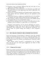
An analog voice signal is digitized in three steps: in the first step, the bandwidth of the
input signal is limited to 300–3400 Hz in order to be able to carry the signal with the limited
bandwidth of a 64 kbit/s timeslot. Afterwards, the signal is sampled at a rate of 8000 times
a second. The next processing step is the quantization of the samples, which means that the
analog samples are converted into eight-bit digital values that can each have a value from 0
to 255. See Figure 1.9.
The higher the volume of the input signal, the higher the amplitude of the sampled value
and its digital representation. In order to be able to also transmit low-volume conversations,
the quantization is not linear over the whole input range but only in certain areas. For small
amplitudes of the input signal a much higher range of digital values is used than for high
amplitude values. The resulting digital data stream is called a pulse code modulated (PCM)
signal. Which volume is represented by which digital eight-bit value is described in the
A-law standard for European networks and in the -law standard in North America.
The use of different standards unfortunately complicates voice calls between networks
that use different standards. Therefore, it is necessary for example to convert a voice signal
for a connection between France and the United States.
12 Communication Systems for the Mobile Information Society
Speech is converted by a
microphone into an
analog signal
Sample frequency: 8000 Hz300 Hz–3.4 kHz
Bandwidth limited
signal
Pulse-amplitude
modulated signal
every 125 µs
13 segment curve
256 values, 8 bits
Digitized
speech signal
at 64 kbit/s
Band-pass
filter
Sampler
Quantitizer
Figure 1.9 Digitization of an analog voice signal
As the MSC controls all connections, it is also responsible for billing. This is done by
creating a billing record for each call which is later transferred to a billing server. The billing
record contains information like the number of caller and calling party, cell ID of the cell
from which the call was originated, time of call origination, the duration of the call, etc.
Calls for prepaid subscribers are treated differently as the charging is already done while the
call is running. The prepaid billing service is usually implemented on an IN system and not
on the MSC as is further described in Section 1.11.
1.6.2 The Visitor Location Register (VLR)
Each MSC has an associated visitor location register (VLR), which holds a record of each
subscriber that is currently served by the MSC (Figure 1.10). These records are only a
copy of the original records, which are stored in the HLR (see Section 1.6.3). The VLR is
mainly used to reduce the signaling between the MSC and the HLR. If a subscriber roams
into the area of an MSC, the data is copied to the VLR of the MSC and is thus locally
available for every connection establishment. The verification of the subscriber’s record at
every connection establishment is necessary, as the record contains information about which
Switching center
MSC
application
with SSN = 8
VLR
application
with SSN = 7
MTP 1–3
SCCP
Incoming signaling messages
for VLR and MSC
Figure 1.10 Mobile switching center (MSC) with integrated visitor location register (VLR)
Global System for Mobile Communications (GSM) 13
services are active and from which services the subscriber is barred. Thus, it is possible, for
example, to bar outgoing calls while allowing incoming calls to prevent abuse of the system.
While the standards allow implementing the VLR as an independent hardware component,
all vendors have implemented the VLR simply as a software component in the MSC. This is
possible because MSC and VLR use different SCCP subsystem numbers (see Section 1.4.1)
and can thus run on a single physical node.
When a subscriber leaves the coverage area of an MSC, the subscriber’s record is copied
from the HLR to the VLR of the new MSC, and is then removed from the VLR of the previous
MSC. The communication with the HLR is standardized in the D-interface specification
which is shown together with other MSC interfaces in Figure 1.8.
1.6.3 The Home Location Register (HLR)
The HLR is the subscriber database of a GSM network. It contains a record for each
subscriber, which contains information about the individually available services.
The international mobile subscriber identity (IMSI) is an internationally unique number
that identifies a subscriber and used for most subscriber-related signaling in the network
(Figure 1.11). The IMSI is stored in the subscriber’s SIM card and in the HLR and is
thus the key to all information about the subscriber. The IMSI consists of the following
parts:
•
The mobile country code (MCC): the MCC identifies the subscriber’s home country.
Table 1.2 shows a number of MCC examples.
•
The mobile network code (MNC): this part of the IMSI is the national part of a subscriber’s
home network identification. A national identification is necessary because there are
usually several independent mobile networks in a single country. In the UK for example
the following MNCs are used: 10 for O2, 15 for Vodafone, 30 for T-Mobile, 33 for
Orange, 20 for Hutchison 3G, etc.
•
The mobile subscriber identification number (MSIN): the remaining digits of the IMSI
form the MSIN, which uniquely identifies a subscriber within the home network.
As an IMSI is internationally unique, it enables a subscriber to use his phone abroad if
a GSM network is available that has a roaming agreement with his home operator. When
the mobile phone is switched on, the IMSI is retrieved from the SIM card and sent to the
MSC. There, the MCC and MNC of the IMSI are analyzed and the MSC is able to request
the subscriber’s record from the HLR of the subscriber’s home network.
Figure 1.11 The international mobile subscriber identity (IMSI)
14 Communication Systems for the Mobile Information Society
Table 1.2 Mobile country codes
MCC Country
234 United Kingdom
310 United States
228 Switzerland
208 France
262 Germany
604 Morocco
505 Australia
Figure 1.12 A terminal program can be used to retrieve the IMSI from the SIM card
For information purposes, the IMSI can also be retrieved from the SIM card with a PC
and a serial cable that connects to the mobile phone. By using a terminal program such
as HyperTerminal, the mobile can be instructed to return the IMSI by using the ‘at +cimi’
command, which is standardized in 3GPP TS 27.007 [4]. Figure 1.12 shows how the IMSI
is returned by the mobile phone.
The phone number of the user, which is called the mobile subscriber ISDN number
(MSISDN) in the GSM standards, has a length of up to 15 digits and consists of the following
parts:
•
The country code is the international code of the subscriber’s home country. The country
code has one to three digits such as +44 for the UK, +1 for the US, +353 for Ireland.
•
The national destination code (NDC) usually represents the code with which the network
operator can be reached. It is normally three digits in length. It should to be noted that
mobile networks in the US use the same NDCs as fixed-line networks. Thus, it is not
possible for a user to distinguish if he is calling a fixed line or a mobile phone. This
Global System for Mobile Communications (GSM) 15
impacts both billing and routing, as the originating network cannot deduct which tariff to
apply from the NDC.
•
The remainder of the MSISDN is the subscriber number, which is unique in the network.
There is usually a 1:1 or 1:N relationship in the HLR between the IMSI and the MSISDN.
Furthermore, a mobile subscriber is normally assigned only a single MSISDN. However, as
the IMSI is the unique identifier of a subscriber in the mobile network, it is also possible to
assign several numbers to a single subscriber.
Another advantage of using the IMSI as the key to all subscriber information instead of
the MSISDN is that the phone number of the subscriber can be changed without replacing
the user’s SIM card or changing any information on it. In order to change the MSISDN,
only the HLR record of the subscriber needs to be changed. In effect, this means that the
mobile station is not aware of its own phone number. This is not necessary because the
MSC automatically adds the user’s MSISDN to the message flow for a mobile-originated
call establishment so it can be presented to the called party.
Many countries have introduced a functionality called mobile number portability (MNP),
which allows a subscriber to keep his MSISDN if he wants to change his mobile network
operator. This is a great advantage for the subscribers and for competition between the mobile
operators, but also implies that it is no longer possible to discern the mobile network to which
the call will be routed from the NDC. Furthermore, the introduction of MNP also increased
the complexity of call routing and billing in both fixed-line and mobile networks, because
it is no longer possible to use the NDC to decide which tariff to apply to a call. Instead of
a simple call-routing scheme based on the NDC, the networks now have to query a mobile
number portability database for every call to a mobile subscriber to find out if the call can
be routed inside the network or if it has to be forwarded to a different national mobile network.
Apart from the IMSI and MSISDN, the HLR contains a variety of information about each
subscriber, such as which services he is allowed to use. Table 1.3 shows a number of ‘basic
services’ that can be activated on a per subscriber basis:
In addition to the basic services described above, the GSM network offers a number of
other services that can also be activated on a per subscriber basis. These services are called
supplementary services and are shown in Table 1.4.
Table 1.3 Basic services of a GSM network
Basic service Description
Telephony If this basic service is activated, a subscriber can use
the voice telephony services of the network. This can
be partly restricted by other supplementary services
which are described below
Short messaging service (SMS) If activated, a subscriber is allowed to use the SMS
Data service Different circuit-switched data services can be
activated for a subscriber with speeds of 2.4, 4.8, 9.6,
and 14.4 kbit/s data calls
FAX Allows or denies a subscriber the use of the FAX
service that can be used to exchange FAX messages
with fixed-line or mobile terminals
16 Communication Systems for the Mobile Information Society
Table 1.4 Supplementary services of a GSM network
Supplementary service Description
Call forward
unconditional (CFU)
If this service is configured, a number can be configured to which all
incoming calls are forwarded immediately [5]. This means that the mobile
phone will not even be notified of the incoming call even if it is
switched on
Call forward busy
(CFB)
This service allows a subscriber to define a number to which calls are
forwarded if he is already engaged in a call when a second call comes in
Call forward no reply
(CFNRY)
If this service is activated, it is possible to forward the call to a
user-defined number if the subscriber does not answer the call within a
certain time. The subscriber can change the number to which to forward
the call to as well as the timeout value (e.g. 25 seconds)
Call forward not
reachable (CFNR)
This service forwards the call if the mobile phone is attached to the
network but is not reachable momentarily (e.g. temporary loss of network
coverage)
Barring of all
outgoing calls
(BAOC)
This functionality can be activated by the network operator if, for example,
the subscriber has not paid his monthly invoice in time. It is also possible
for the network operator to allow the subscriber to change the state of this
feature together with a PIN (personal identification number) so the
subscriber can lend the phone to another person for incoming calls only [6]
Barring of all
incoming calls
(BAIC)
Same functionality as provided by BAOC for incoming calls [6]
Call waiting (CW) This feature allows signaling an incoming call to a subscriber while he is
already engaged on another call [7]. The first call can then be put on hold
to accept the incoming call. The feature can be activated or barred by the
operator and switched on or off by the subscriber
Call hold (HOLD) This functionality is used to accept an incoming call during an already
active call or to start a second call [7]
Calling line
identification
presentation (CLIP)
If activated by the operator for a subscriber, the functionality allows the
switching center to forward the number of the caller
Calling line
identification
restriction (CLIR)
If allowed by the network, the caller can instruct the network not to show
his phone number to the called party
Connected line
presentation (COLP)
Shows the calling party the MSISDN to which a call is forwarded, if call
forwarding is active at the called party side
Connected line
presentation
restriction (COLR)
If COLR is activated at the called party, the calling party will not be
notified of the MSISDN the call is forwarded to
Multi party (MPTY) Allows subscribes to establish conference bridges with up to six
subscribers [8]
Global System for Mobile Communications (GSM) 17
Most supplementary services can be activated by the network operator on a per subscriber
basis and allow the operator to charge an additional monthly fee for some services if desired.
Other services, like multi party, can be charged on a per use basis. Most services can be
configured by the subscriber via a menu on the mobile phone. The menu, however, is just
a graphical front end for the user and the mobile phone translates the user’s commands into
numerical strings which start with a ‘
∗
’ character. These strings are then sent to the network
by using an unstructured supplementary service data (USSD) message. The codes are stan-
dardized in 3GPP TS 22.030 [9] and are thus identical in all networks. As the menu is only
a front end for the USSD service, the user can also input the USSD strings himself via the
keypad. After pressing the ‘send’ button, which is usually the button that is also used to start
a phone call after typing in a phone number, the mobile phone sends the string to the HLR via
the MSC, where the string is analyzed and the requested operation is performed. For example,
call forwarding to another phone (e.g. 0782 192 8355), while a user is already engaged in
another call (CFB), is activated with the following string:
∗∗
67
∗
07821928355# + call button.
1.6.4 The Authentication Center
Another important part of the HLR is the authentication center (AC). The AC contains an
individual key per subscriber (Ki) which is a copy of the Ki in the SIM card of the subscriber.
As the Ki is secret, it is stored in the AC and especially on the SIM card in a way that
prevents it being read directly.
For many operations in the network, for instance during the establishment of a call, the
subscriber is identified by using this key. Thus it can be ensured that the subscriber’s identity
is not misused by a third party. Figures 1.13 and 1.14 show how the authentication process
is performed.
The authentication process is initiated when a subscriber establishes a signaling connection
with the network before the actual request (e.g. call establishment request) is sent. In the first
step of the process, the MSC requests an authentication triplet from the HLR/authentication
center. The AC retrieves the Ki of the subscriber and the authentication algorithm (A3
algorithm) based on the IMSI of the subscriber that is part of the message from the MSC.
The Ki is then used together with the A3 algorithm and a random number to generate the
authentication triplet which contains the following values:
•
RAND: a 128-bit random number.
•
SRES: the signed response (SRES) is generated by using Ki, RAND, and the authentication
A3 algorithm, and has a length of 32 bits.
•
Kc: the ciphering key, Kc, is also generated by using Ki and RAND. It is used for
the ciphering of the connection once the authentication has been performed successfully.
Further information on this topic can be found in Section 1.7.5.
Figure 1.13 Creation of a signed response (SRES)
18 Communication Systems for the Mobile Information Society
t
SIM/Mobile station MSC HLR/AC
Connection establishment
(e.g. location update or call establishment)
MAP: Send authentication triplets
(IMSI)
Send authentication triplets ack.
(RAND, SRES, Kc)
DTAP: Authentication request
(RAND)
DTAP: Authentication response
(SRES*)
SRES* = SRES?
Connection is maintained,
activation of ciphering
Figure 1.14 Message flow during the authentication of a subscriber
RAND, SRES, and Kc are then returned to the MSC, which then performs the authen-
tication of the subscriber. It is important to note that the secret Ki key never leaves the
authentication center.
In order to speed up subsequent connection establishments the AC usually returns several
authentication triplets per request. These are buffered by the MSC/VLR and are used during
the next connection establishments.
In the next step, the MSC sends the RAND inside an authentication request message to
the mobile station. The terminal forwards the RAND to the SIM card which then uses the
Ki and the authentication A3 algorithm to generate a signed response (SRES
∗
). The SRES
∗
is returned to the mobile station and then sent back to the MSC inside an authentication
response message. The MSC then compares SRES and SRES
∗
and if they are equal the
subscriber is authenticated and allowed to proceed with the communication.
As the secret key, Ki, is not transmitted over any interface that could be eavesdropped
on, it is not possible for a third party to correctly calculate an SRES. As a fresh random
number is used for the next authentication, it is also pointless to intercept the SRES
∗
and use it for another authentication. A detailed description of the authentication proce-
dure and many other procedures between the mobile station and the core network can be
found in [10].
Figure 1.15 shows some parts of an authentication request and an authentication response
message. Apart from the format of RAND and SRES, it is also interesting to note the
different protocols which are used to encapsulate the message (see Section 1.4.2).
Global System for Mobile Communications (GSM) 19
Extract of a decoded Authentication Request message
SCCP MSG: Data Form 1
DEST. REF ID: 0B 02 00
DTAP MSG LENGTH: 19
PROTOCOL DISC.: Mobility Management
DTAP MM MSG: Auth. Request
Ciphering Key Seq.: 0
RAND in hex: 12 27 33 49 11 00 98 45
87 49 12 51 22 89 18 81 (16 byte = 128 bit)
Extract of a decoded Authentication Response message
SCCP MSG: Data Form 1
DEST. REF ID: 00 25 FE
DTAP MSG LENGTH: 6
PROTOCOL DISC.: Mobility Management
DTAP MM MSG: Auth. Response
SRES in hex: 37 21 77 61 (4 byte = 32 bit)
Figure 1.15 Authentication between network and mobile station
1.6.5 The Short Messaging Service Center (SMSC)
Another important network element is the short message service center (SMSC) which is
used to store and forward short messages. The short messaging service was only introduced
about four years after the first GSM networks went into operation as add on and has been
specified in 3GPP TS 23.040 [11]. Most industry observers were quite skeptical at the time
as the general opinion was that if it is needed to convey some information, it is done by
calling someone rather than to cumbersomely type in a text message on the small keypad.
However, they were proven wrong and today most GSM operators generate over 15% of
their revenue from the short messaging service alone with a total number of over 25 billion
SMS messages exchanged annually in the United Kingdom.
The short messaging service can be used for person-to-person messaging as well as for
notification purposes of received email messages or a new call forwarded to the voice mail
system. The transfer method for both cases is identical.
The sender of an SMS prepares the text for the message and then sends the SMS via a
signaling channel to the MSC. As a signaling channel is used, an SMS is just an ordinary
DTAP SS-7 message and thus, apart from the content, very similar to other DTAP messages,
such as a location update message or a setup message to establish a voice call. Apart from the
text, the SMS message also contains the MSISDN of the destination party and the address
of the SMSC which the mobile station has retrieved from the SIM card. When the MSC
receives an SMS from a subscriber it transparently forwards the SMS to the SMSC. As the
message from the mobile station contains the address of the subscriber’s SMSC, international
roaming is possible and the foreign MSC can forward the SMS to the home SMSC without
the need for an international SMSC database. See Figure 1.16.
In order to deliver a message, the SMSC analyses the MSISDN of the recipient and
retrieves its current location (the responsible MSC) from the HLR. The SMS is then forwarded
to the responsible MSC. If the subscriber is currently attached, the MSC tries to contact the
mobile station and if an answer is received, the SMS is forwarded. Once the mobile station
20 Communication Systems for the Mobile Information Society
Figure 1.16 SMS delivery principle
has confirmed the proper reception of the SMS, the MSC notifies the SMSC as well and the
SMS is deleted from the SMSC’s data storage.
If the subscriber is not reachable because the battery of the mobile station is empty, the
network coverage has been lost temporarily, or if the device is simply switched off, it is not
possible to deliver the SMS. In this case, the message waiting flag is set in the VLR and the
SMSC is stored in the SMSC. Once the subscriber communicates with the MSC, the MSC
notifies the SMSC to reattempt delivery.
As the message waiting flag is also set in the HLR, the SMS also reaches a subscriber
that has switched off the mobile station in London for example and switches it on again
after a flight to Los Angeles. When the mobile station is switched on in Los Angeles, the
visited MSC reports the location to the subscriber’s home HLR (location update). The HLR
then sends a copy of the user’s subscription information to the MSC/VLR in Los Angeles
including the message waiting flag and thus the SMSC can also be notified that the user is
reachable again.
The SMS delivery mechanism does not unfortunately include a delivery reporting func-
tionality for the sender of the SMS. The sender is only notified that the SMS has been
correctly received by the SMSC. If and when the SMS is also correctly delivered to the
recipient, however, is not signalled to the originator of the message. Most SMSC vendors
have therefore implemented their own proprietary solutions. Some vendors use a code for this
purpose that the user has to include in the text message. With some operators for example,
‘
∗
N#’ or ‘
∗
T#’ can be put into the text message at the beginning to indicate to the SMSC
that the sender wishes a delivery notification. The SMSC then removes the three-character
code and returns an SMS to the originator once the SMS was successfully delivered to the
recipient.
1.7 The Base Station Subsystem (BSS)
While most functionality required in the NSS for GSM could be added via additional
software, the BSS had to be developed from scratch. This was mainly necessary because
earlier generation systems were based on analog transmission over the air interface and thus
had not much in common with the GSM BSS.
Global System for Mobile Communications (GSM) 21
1.7.1 Frequency Bands
In Europe, GSM was initially only specified for operation in the 900 MHz band between
890–915 MHz in the uplink direction and between 935–960 MHz in the downlink direction
(Figure 1.17). ‘Uplink’ refers to the transmission from the mobile station to the network and
‘downlink’ to the transmission from the network to the mobile station. The bandwidth of
25 MHz is split into 125 channels with a bandwidth of 200 kHz each.
It soon became apparent that the number of available channels was not sufficient to cope
with the growing demand in many European countries. Therefore, the regulating bodies
assigned an additional frequency range for GSM which uses the frequency band from
1710–1785 MHz for the uplink and 1805–1880 for the downlink. Instead of a total bandwidth
of 25 MHz as in the 900 MHz range, the 1800 MHz band offers 75 MHz of bandwidth
which corresponds to 375 additional channels. The functionality of GSM is identical on both
frequency bands, with the channel numbers, also referred to as the absolute radio frequency
channel numbers (ARFCNs), being the only difference. See Table 1.5.
While GSM was originally intended only as a European standard, the system soon spread to
countries in other parts of the globe. In countries outside Europe, GSM sometimes competes
with other technologies, such as CDMA. Today, only a few countries, like Japan and South
Korea, are not covered by GSM systems. However, some of the operators in these countries
operate W-CDMA UMTS networks (see Chapter 3). Therefore, GSM/UMTS subscribers
with dual-mode phones can also roam in these countries.
In North America, analog mobile networks continued to be used for some time before
second-generation networks, with GSM being one of the technologies used, were introduced.
Unfortunately, however, the 900 MHz as well as the 1800 MHz band were already in use
by other systems and thus the North American regulating body chose to open frequency
bands for the new systems in the 1900 MHz band and later on in the 850 MHz band. The
disadvantage of this approach is that many US GSM mobile phones cannot be used in Europe
Figure 1.17 GSM uplink and downlink in the 900 MHz frequency band
Table 1.5 GSM frequency bands
Band ARFCN Uplink (MHz) Downlink (MHz)
GSM 900 (Primary) 0–124 890–915 935–960
GSM 900 (Extended) 975–1023, 0–124 880–915 925–960
GSM 1800 512–885 1710–1785 1805–1880
GSM 1900 (North America) 512–810 1850–1910 1930–1990
GSM 850 (North America) 128–251 824–849 869–894
GSM-R 0–124, 955–1023 876–915 921–960
22 Communication Systems for the Mobile Information Society
and vice versa. Fortunately, many new GSM and UMTS phones support the US frequency
bands as well as the European frequency bands, which are also used in most countries in
other parts of the world. These tri-band or quad-band phones thus enable a user to truly
roam globally.
The GSM standard is also used by railway communication networks in Europe and other
parts of the world. For this purpose, GSM was enhanced to support a number of private
mobile radio and railway specific functionalities and is known as GSM-R. The additional
functionalities include:
•
The voice group call service (VGCS): this service offers a circuit-switched walkie-talkie
functionality to allow subscribers that have registered to a VGCS group to communicate
with all other subscribers in the area who have also subscribed to the group. In order to
talk, the user has to press a push to talk button. If no other subscriber holds the uplink, the
network grants the request and blocks the uplink for all other subscribers while the push to
talk button is pressed. The VGCS service is very efficient especially if many subscribers
participate in a group call, as all mobile stations that participate in the group call listen
to the same timeslot in downlink direction. Further information about this service can be
found in 3GPP TS 43.068 [12].
•
The voice broadcast service (VBS): same as VGCS with the restriction that only the
originator of the call is allowed to speak. Further information about this service can be
found in 3GPP TS 43.069 [13].
•
Enhanced multi level precedence and preemption (eMLPP): this functionality, which is
specified in 3GPP TS 23.067 [14], is used to attach a priority to a point-to-point, VBS,
or VGCS call. This enables the network and the mobile stations to automatically preempt
ongoing calls for higher priority calls to ensure that emergency calls (e.g. a person
has fallen on the track) is not blocked by lower priority calls and a lack of resources
(e.g. because no timeslots are available).
As GSM-R networks are private networks, it has been decided to assign a private frequency
band in Europe for this purpose which is just below the public 900 MHz GSM band. To
use GSM-R, mobile phones need to be slightly modified to be able to send and receive
in this frequency range. This requires only minor software and hardware modifications. In
order to be also able to use the additional functionalities described above, further exten-
sions of the mobile station software are necessary. More about GSM-R can be found at
[15].
1.7.2 The Base Transceiver Station (BTS)
Base stations, which are also called base transceiver stations (BTSs), are the most visible
network elements of a GSM system (Figure 1.18). Compared to fixed-line networks, the base
stations replace the wired connection to the subscriber with a wireless connection which is
also referred to as the air interface. The base stations are also the most numerous components
of a mobile network as according to press reports each wireless operator in the UK for
example has well over 10,000 base stations.
In theory, a base station can cover an area with a radius of up to 35 km. This area is
also called a cell. As a base station can only serve a limited number of simultaneous users,
Global System for Mobile Communications (GSM) 23
Figure 1.18 A typical antenna of a GSM base station. The optional microwave directional antenna
(round antenna at the bottom of the mast) connects the base station with the GSM network
cells are much smaller in practice especially in dense urban environments. There, cells cover
areas with a radius between 3 and 4 km in residential and business areas, and down to only
several 100 m and minimal transmission power in heavily frequented areas like shopping
centers and downtown streets. Even in rural areas, a cell’s coverage area is usually less then
15 km as the transmission power of the mobile station of one or two watts is the limiting
factor in this case.
As the emissions of different base stations of the network must not interfere with each other,
all neighboring cells have to send on different frequencies. As can be seen in Figure 1.19, a
singe base station usually has quite a number of neighboring sites. Therefore, only a limited
number of different frequencies can be used per base station in order to increase capacity.
To increase the capacity of a base station, the coverage area is usually split into two or
three sectors which are then covered on different frequencies by a dedicated transmitter.
Adjacent cells which
have to send on a differen
t
frequency
Neighbor cells
which are further
away
Figure 1.19 Cellular structure of a GSM network
24 Communication Systems for the Mobile Information Society
Figure 1.20 Sectorized cell configurations
This allows the reuse of frequencies in two-dimensional space better than if only a single
frequency was used for the whole base station. Each sector of the base station therefore
forms its own independent cell (Figure 1.20).
1.7.3 The GSM Air Interface
The transmission path between the BTS and the mobile terminal is referred to in the
GSM specifications as the air interface or the Um interface. To allow the base station
to communicate with several subscribers simultaneously, two methods are used. The first
method is frequency division multiple access (FDMA) which means that users communicate
with the base station on different frequencies. The second method used is time division
multiple access (TDMA). See Figure 1.21. GSM uses carrier frequencies with a bandwidth
of 200 kHz over which up to eight subscribers can communicate with the base station
simultaneously.
Subscribers are time multiplexed by dividing the carrier into frames with durations of
4.615 ms. Each frame contains eight physically independent timeslots, each for communica-
tion with a different subscriber. The timeframe of a timeslot is called a burst and the burst
duration is 577 microseconds. If a mobile station is allocated timeslot number two for a voice
call for example, the mobile station will send and receive only during this burst. Afterwards,
it has to wait until the next frame before it is allowed to send again.
By combining the two multiple access schemes it is possible to approximately calculate
the total capacity of a base station. For the following example it is assumed that the base
station is split into three sectors and each sector is covered by an independent cell. Each
cell is equipped with two transmitters and receivers, a configuration that is used quite often.
In each sector, 2 × 8 = 16 timeslots are thus available. Two timeslots are usually assigned
for signaling purposes which leaves 14 timeslots per sector for user channels. Let us further
assume that four timeslots or more are used for the packet-switched GPRS service (see
Chapter 2). Therefore, 10 timeslots are left for voice calls per sector, which amounts to 30
Figure 1.21 A GSM TDMA frame
Global System for Mobile Communications (GSM) 25
channels for all sectors of the base station. In other words this means that 30 subscribers can
communicate simultaneously per base station.
A single BTS, however, provides service for a much higher number of subscribers, as they
do not all communicate at the same time. Mobile operators, therefore, base their network
dimensioning on a theoretical call profile model in which the number of minutes a subscriber
statistically uses the system per hour is one of the most important parameters. A commonly
used value for the number of minutes a subscriber uses the system per hour is one minute.
This means that a base station is able to provide service for 60 times the number of active
subscribers. In this example a base station with 30 channels is therefore able to provide
service for about 1800 subscribers.
This number is quite realistic as the following calculation shows: Vodafone Germany had
a subscriber base of about 25 million in 2005. If this value is divided by the number of
subscribers per cell, the total number of base stations required to serve such a large subscriber
base can be determined. With our estimation above, the number of base stations required for
the network would be about 14,000. This value is quite accurate and in line with numbers
published by the operator.
Each burst of a TDMA frame is divided into a number of different sections as shown
in Figure 1.22. Each burst is encapsulated by a guard time in which no data is sent. This
is necessary because the distance of the different subscribers relative to the base station
can change while they are active. As airwaves ‘only’ propagate through space at the speed
of light, the signal of a far away subscriber takes a longer time to reach the base station
compared to a subscriber that is closer to the base station. In order to prevent any overlap,
guard times were introduced. These parts of the burst are very short, as the network actively
controls the timing advance of the mobile station. More about this topic can be found below.
The training sequence in the middle of the burst always contains the same bit pattern.
It is used to compensate for interference caused for example by reflection, absorption, and
multi-path propagation. On the receiver side these effects are countered by comparing the
received signal to the training sequence and thus adapting the analog filter parameters for
the signal. The filter parameters calculated this way can then be used to modify the rest of
the signal and thus to better recreate the original signal.
At the beginning and end of each burst, another well-known bit pattern is sent to enable
the receiver to detect the beginning and end of a burst correctly. These fields are called
‘tails’. The actual user data of the burst, i.e. the digitized voice signal, is sent in the two
user data fields with a length of 57 bits each. This means, that a 577-microsecond burst
transports 114 bits of user data. Finally, each frame contains two bits to the left and right of
the training sequence which are called ‘stealing bits’. These bits indicate if the data fields
Figure 1.22 A GSM burst
26 Communication Systems for the Mobile Information Society
contain user data or are used (‘stolen’) for urgent signaling information. User data of bursts
which carry urgent signaling information, however, is lost. As shown below, the speech
decoder is able to cope with short interruptions of the data stream quite well and thus are
not normally audible to the user.
For the transmission of user or signaling data, the timeslots are arranged into logical
channels. A user data channel for the transmission of digitized voice data for example is a
logical channel. On the first carrier frequency of a cell the first two timeslots are usually
used for common logical signaling channels while the remaining six independent timeslots
are used for user data channels or GPRS. As there are more logical channels then physical
channels (timeslots) for signaling, 3GPP TS 45.002 [16] describes how 51 frames are grouped
into a multiframe to be able to carry a number of different signaling channels over the same
timeslot. In such a multiframe, which is infinitely repeated, it is specified in which bursts
on timeslots 0 and 1 which logical channels are transmitted. For user data timeslots (e.g.
voice) the same principle is used. Instead of 51 frames, these timeslots are grouped into
a 26-multiframe pattern. In order to visualize this principle, Figure 1.23 shows how the
eight timeslots of a frame are grouped into a two-dimensional table. Figure 1.24 then uses
this principle to show how the logical channels are assigned to physical timeslots in the
multiframe.
Logical channels are arranged into two groups. If data on a logical channel is dedicated
to a single user, the channel is called a dedicated channel. If the channel is used for data
that needs to be distributed to several users, the channel is called a common channel.
Let us take a look at the dedicated channels first:
•
The traffic channel (TCH) is a user data channel. It can be used to transmit a digitized
voice signal or circuit-switched data services of up to 14.4 kbit/s.
•
The fast associated control channel (FACCH) is transmitted on the same timeslot as a
TCH. It is used to send urgent signaling messages like a handover command. As these
messages do not have to be sent very often, no dedicated physical bursts are allocated
to the FACCH. Instead, user data is removed from a TCH burst. In order to inform the
Figure 1.23 Arrangement of bursts of a frame for the visualization of logical channels in Figure 1.24
Global System for Mobile Communications (GSM) 27
FN TS-0 TS-1 FN TS-2 TS-7
0 FCCH SDCCH/0 0 TCH TCH
1 SCH SDCCH/0 1 TCH TCH
2 BCCH SDCCH/0 2 TCH TCH
3 BCCH SDCCH/0 3 TCH TCH
4 BCCH SDCCH/1 4 TCH TCH
5 BCCH SDCCH/1 5 TCH TCH
6 AGCH/PCH SDCCH/1 6 TCH TCH
7 AGCH/PCH SDCCH/1 7 TCH TCH
8 AGCH/PCH SDCCH/2 8 TCH TCH
9 AGCH/PCH SDCCH/2 9 TCH TCH
10 FCCH SDCCH/2 10 TCH TCH
11 SCH SDCCH/2 11 TCH TCH
12 AGCH/PCH SDCCH/3 12 SACCH SACCH
13 AGCH/PCH SDCCH/3 13 TCH TCH
14 AGCH/PCH SDCCH/3 14 TCH TCH
15 AGCH/PCH SDCCH/3 15 TCH TCH
16 AGCH/PCH SDCCH/4 16 TCH TCH
17 AGCH/PCH SDCCH/4 17 TCH TCH
18 AGCH/PCH SDCCH/4 18 TCH TCH
19 AGCH/PCH SDCCH/4 19 TCH TCH
20 FCCH SDCCH/5 20 TCH TCH
21 SCH SDCCH/5 21 TCH TCH
22 SDCCH/0 SDCCH/5 22 TCH TCH
23 SDCCH/0 SDCCH/5 23 TCH TCH
24 SDCCH/0 SDCCH/6 24 TCH TCH
25 SDCCH/0 SDCCH/6 25 free free
26 SDCCH/1 SDCCH/6 0 TCH TCH
27 SDCCH/1 SDCCH/6 1 TCH TCH
28 SDCCH/1 SDCCH/7 2 TCH TCH
29 SDCCH/1 SDCCH/7 3 TCH TCH
30 FCCH SDCCH/7 4 TCH TCH
31 SCH SDCCH/7 5 TCH TCH
32 SDCCH/2 SACCH/0 6 TCH TCH
33 SDCCH/2 SACCH/0 7 TCH TCH
34 SDCCH/2 SACCH/0 8 TCH TCH
35 SDCCH/2 SACCH/0 9 TCH TCH
36 SDCCH/3 SACCH/1 10 TCH TCH
37 SDCCH/3 SACCH/1 11 TCH TCH
38 SDCCH/3 SACCH/1 12 SACCH SACCH
39 SDCCH/3
SACCH/1 13 TCH TCH
40 FCCH SACCH/2 14 TCH TCH
41 SCH SACCH/2 15 TCH TCH
42 SACCH/0 SACCH/2 16 TCH TCH
43
SACCH/0 SACCH/2 17 TCH TCH
44 SACCH/0 SACCH/3 18 TCH TCH
45 SACCH/0 SACCH/3 19 TCH TCH
46
SACCH/1 SACCH/3 20 TCH TCH
47 SACCH/1 SACCH/3 21 TCH TCH
48
SACCH/1 free 22 TCH TCH
49 SACCH/1 free 23 TCH TCH
50 free free 24 TCH TCH
25 free
free
Figure 1.24 Use of timeslots in downlink direction as per 3GPP TS 45.002 [16]
28 Communication Systems for the Mobile Information Society
mobile station, the stealing bits to the left and right of the training sequence, as shown in
Figure 1.22, are used. This is the reason why the FACCH is not shown in Figure 1.24.
•
The slow associated control channel (SACCH) is also assigned to a dedicated connection.
It is used in the uplink direction to report signal quality measurements of the serving cell
and neighboring cells to the network. The network then uses these values for handover
decisions and power control. In the downlink direction, the SACCH is used to send power
control commands to the mobile station. Furthermore, the SACCH is used for timing
advance control which is described in Section 1.7.4 and Figure 1.29. As these messages
are only of low priority and the necessary bandwidth is very small, only a few bursts are
used on a 26 multiframe at fixed intervals.
•
The standalone dedicated control channel (SDCCH) is a pure signaling channel which
is used during call establishment when a subscriber has not yet been assigned a traffic
channel. Furthermore, the channel is used for signaling which is not related to call
establishment such as for the location update procedure or for sending or receiving a text
message (SMS).
Besides the dedicated channels, which are always assigned to a single user, there are a
number of common channels that are monitored by all subscribers in a cell:
•
The synchronization channel (SCH) is used by mobile stations during network and cell
searches.
•
The frequency correction channel (FCCH) is used by the mobile stations to calibrate their
transceiver units und is also used to detect the beginning of a multiframe.
•
The broadcast common control channel (BCCH) is the main information channel of a
cell and broadcasts SYS_INFO messages that contain a variety of information about the
network. The channel is monitored by all mobile stations, which are switched on but
currently not engaged in a call or signaling connection (idle mode), and broadcasts among
many other things the following information:
– the MCC and MNC of the cell;
– the identification of the cell which consists of the location area code (LAC) and the
cell ID;
– to simplify the search for neighboring cells for a mobile station, the BCCH also contains
information about the frequencies used by neighboring cells. Thus, the mobile station
does not have to search the complete frequency band for neighboring cells.
•
The paging channel (PCH) is used to inform idle subscribers of incoming calls or SMS
messages. As the network is only aware of the location area the subscriber is roaming
in, the paging message is broadcast in all cells belonging to the location area. The most
important information element of the message is the IMSI of the subscriber or a temporary
identification called the temporary mobile subscriber identity (TMSI). A TMSI is assigned
to a mobile station during the network attach procedure and can be changed by the network
every time the mobile station contacts the network once encryption has been activated.
Thus, the subscriber has to be identified with the IMSI only once and is then addressed
with a constantly changing temporary number when encryption is not yet activated for
the communication. This increases anonymity in the network and prevents eavesdroppers
from creating movement profiles of subscribers.
Global System for Mobile Communications (GSM) 29
•
The random access channel (RACH) is the only common channel in the uplink direction.
If the mobile station receives a message via the PCH that the network is requesting a
connection establishment or if the user wants to establish a call or send an SMS, the
RACH is used for the initial communication with the network. This is done by sending
a channel request message. Requesting a channel has to be done via a ‘random’ channel
because subscribers in a cell are not synchronized with each other. Thus, it cannot be
ensured that two devices do not try to establish a connection at the same time. Only once
a dedicated channel (SDCCH) has been assigned to the mobile station by the network can
there no longer be any collision between different subscribers of a cell. If a collision occurs
during the first network access, the colliding messages are lost and the mobile stations do
not receive an answer from the network. Thus, they have to repeat their channel request
messages after expiry of a timer which is set to an initial random value. This way, it is
not very likely that the mobile stations will interfere with each other again during their
next connection establishment attempts because they are performed at different times.
•
The access grant channel (AGCH): if a subscriber sends a channel request message on the
RACH, the network allocates an SDCCH or in exceptional cases a TCH and notifies the
subscriber on the AGCH via an immediate assignment message. The message contains
information about which SDCCH or TCH the subscriber is allowed to use.
Figure 1.25 shows how PCH, AGCH, and SDCCH are used during the establishment of a
signaling link between the mobile station and the network. The BSC, which is responsible for
assigning SDCCH and TCH channels of a base station, is further described in Section 1.7.4.
As can also be seen in Figure 1.24, not all bursts on timeslots 2 to 7 are used for traffic
channels. Every twelfth burst of a timeslot it used for the SACCH. Furthermore, the 25th
Figure 1.25 Establishment of a signaling connection
30 Communication Systems for the Mobile Information Society
burst is also not used for carrying user data. This gap is used to enable the mobile station
to perform signal strength measurements of neighboring cells on other frequencies. This is
necessary so that the network can redirect the connection into a different cell (handover) to
maintain the call while the user is moving.
The GSM standard offers two possibilities to use the available frequencies. The simplest
case, which has been described so far, is the use of a constant carrier frequency (ARFCN) for
each channel. In order to improve the transmission quality it is also possible to use alternating
frequencies for a single channel of a cell. This concept is known as frequency hopping
and changes the carrier frequency for every burst during a transmission. This increases the
probability that only few bits are lost if one carrier frequency experiences a lot of interference
from other sources like neighboring cells. In the worst case only a single burst is affected
because the next burst is already sent on a different frequency. Up to 64 different frequencies
can be used per base station for frequency hopping. In order to inform the mobile of the
use of frequency hopping, the immediate assignment message used during the establishment
of a signaling link contains all the information about which frequencies are used and which
hopping pattern is applied to the connection.
For carriers that transport the SCH, FCCH, and BCCH channels, frequency hopping must
not be used. This restriction is necessary because it would be very difficult for mobile
stations to find neighboring cells.
In practice, network operators use static frequencies as well as frequency hopping in their
networks.
The interface which connects the base station to the network and which is used to carry
the information for all logical channels is called the A-bis interface. An E-1 connection is
usually used for the A-bis interface and due to its 64 kbit/s timeslot architecture the logical
channels are transmitted in a different way than on the air interface. All common channels
as well as the information sent and received on the SDCCH and SACCH channels are sent
over one or more common 64 kbit/s E-1 timeslots. This is possible because these channels
are only used for signaling data which is not time critical. On the A-bis interface these
signaling messages are sent by using the link access protocol (LAPD). This protocol was
initially designed for the ISDN D-channel of fixed-line networks and has been reused for
GSM with only minor modifications.
For traffic channels that use a bandwidth of 13 kbit/s on the A-bis interface, only one-
quarter of an E-1 timeslot is used. This means that all eight timeslots of an air interface frame
can be carried on only two timeslots of the E-1 interface. A base station composed of three
sectors which uses two carriers each thus requires 12 timeslots on the A-bis interface plus an
additional timeslot for the LAPD signaling. The remaining timeslots of the E-1 connection
can be used for the communication between the network and other base stations. For this
purpose, several cells are usually daisy chained via a single E-1 connection. See Figure 1.26.
1.7.4 The Base Station Controller (BSC)
While the base station is the interface element that connects the mobile stations with the
network, the base station controller (BSC) is responsible for the establishment, release, and
maintenance of all connections of cells which are connected to it.
If a subscriber wants to establish a voice call, send an SMS, etc., the mobile station sends
a channel request message to the BSC as shown in Figure 1.25. The BSC then checks if
Global System for Mobile Communications (GSM) 31
Figure 1.26 Mapping of E-1 timeslots to air interface timeslots
an SDCCH is available and activates the channel in the BTS. Afterwards, the BSC sends
an immediate assignment message to the mobile station on the AGCH which includes the
number of the assigned SDCCH. The mobile station then uses the SDCCH to send DTAP
messages which the BSC forwards to the MSC.
The BSC is also responsible for establishing signaling channels for incoming calls or SMS
messages. In this case, the BSC receives a paging message from the MSC which contains
the IMSI and TMSI of the subscriber, as well as the location area ID in which the subscriber
is currently located. The BSC in turn has a location area database which it uses to identify
all cells in which the subscriber needs to be paged. When the mobile station receives the
paging message, it responds to the network in the same way as in the example above by
sending a channel request message.
The establishment of a traffic channel for voice calls is always requested by the MSC
for both mobile-originated and mobile-terminated calls. Once the mobile station and the
MSC have exchanged all necessary information for the establishment of a voice call via an
SDCCH, the MSC sends an assignment request for a voice channel to the BSC as shown in
Figure 1.27.
The BSC then verifies if a TCH is available in the requested cell and if so, activates the
channel in the BTS. Afterwards, the mobile station is informed via the SDCCH that a TCH
is now available for the call. The mobile station then changes to the TCH and FACCH. To
inform the BTS that it has switched to the new channel, the mobile station sends a message
to the BTS on the FACCH which is acknowledged by the BTS. In this way, the mobile also
has a confirmation that its signal can be decoded correctly by the BTS. Finally, the mobile
station sends an assignment complete message to the BSC which in turn informs the MSC
of the successful establishment of the traffic channel.
Apart from the establishment and release of a connection, another important task of the
BSC is the maintenance of the connection. As subscribers can roam freely through the
network while a call is ongoing it can happen that the subscriber roams out of the coverage
area of the cell in which the call was initially established. In this case, the BSC has to
redirect the call to the appropriate cell. This procedure is called handover. In order to be able
to perform a handover into another cell, the BSC requires signal quality measurements for
the air interface. The results of the downlink signal quality measurements are reported to the
32 Communication Systems for the Mobile Information Society
Figure 1.27 Establishment of a traffic channel (TCH)
BSC by the mobile station, which continuously performs signal quality measurements which
it reports via the SACCH to the network. The uplink signal quality is constantly measured
by the BTS and also reported to the BSC. Apart from the signal quality of the user’s current
cell, it is also important that the mobile station reports the quality of signals it receives from
other cells. To enable the mobile station to perform these measurements, the network sends
the frequencies of neighbouring cells via the SACCH during an ongoing call. The mobile
station then uses this information to perform the neighbouring cell measurements while the
network communicates with other subscribers and reports the result via measurement report
messages in the uplink SACCH.
The network receives these measurement values and is thus able to periodically evaluate
if a handover of an ongoing call to a different cell is necessary. Once the BSC decides to
perform a handover, a TCH is activated in the new cell as shown in Figure 1.28. Afterwards,
the BSC informs the mobile station via the old cell with a handover command message that is
sent over the FACCH. Important information elements of the message are the new frequency
and timeslot number of the new TCH. The mobile station then changes its transmit and
receive frequency, synchronizes to the new cell if necessary, and sends a handover access
message in four consecutive bursts. In the fifth burst, an SABM message is sent which is
acknowledged by the BTS to signal to the mobile station that the signal can be received. At
the same time, the BTS informs the BSC of the successful reception of the mobile station’s
signal with an establish indication message. The BSC then immediately redirects the speech
path into the new cell.
From the mobile’s point of view the handover is now finished. The BSC, however, has
to release the TCH in the old cell and has to inform the MSC of the performed handover
Global System for Mobile Communications (GSM) 33
Figure 1.28 Message flow during a handover procedure
before the handover is finished from the network’s point of view. The message to the MSC
is only informative and has no impact on the continuation of the call.
In order to reduce interference, the BSC is also in charge of controlling the transmission
power for every air interface connection. For the mobile station an active power control
has the advantage that the transmission power can be reduced under favorable reception
conditions. The control of the mobile station’s transmission power is done using the signal
quality measurements of the BTS for the connection. If the mobile station’s transmission
power has to be increased or decreased, the BSC sends a power control message to the
BTS. The BTS in turn forwards the message to the mobile station and repeats the message
on the SACCH in every frame. In practice, it can be observed that power control and
adaptation is performed every one to two seconds. During call establishment, the mobile
station always uses the highest allowed power output level which is then reduced or increased
again by the network step by step. Table 1.6 gives an overview of the mobile station power
classes. A distinction is made for the 900 MHz versus the 1800 MHz band. While mobile
stations operating on the 900 MHz band are allowed to use up to 2 watts, connections on
the 1800 MHz band are limited to 1 watt. For stationary devices or car phones with external
antennas, power values for up to 8 watts are allowed. The power values in the table represent
the power output when the transmitter is active in the assigned timeslot. As the mobile
station only sends on one of the eight timeslots of a frame, the average power output of the
mobile station is only one-eighth of this value. The average power output of a mobile station
which sends with a power output of 2 watts is thus only 250 milliwatts.
The BSC is also able to control the power output of the base station. This is done by
evaluating the signal measurements of the mobile stations in the current cell. It is important to
note that power control can only be performed for downlink carriers which do not broadcast
the common channels like FCH, SCH, and BCCH of a cell. On such carriers the power
output has to be constant in order to allow mobile stations, which are currently located in
other cells of the network, to perform their neighbouring cell measurements. This would not
34 Communication Systems for the Mobile Information Society
Table 1.6 GSM power levels and corresponding power output
GSM 900
Power level
GSM 900
Power output
GSM 1800
Power level
GSM 1800
Power output
(0–2) (8 W)
52W 01W
6 1.26 W 1 631 mW
7 794 mW 2 398 mW
8 501 mW 3 251 mW
9 316 mW 4 158 mW
10 200 mW 5 100 mW
11 126 mW 6 63 mW
12 79 mW 7 40 mW
13 50 mW 8 25 mW
14 32 mW 9 16 mW
15 20 mW 10 10 mW
16 13 mW 11 6.3 mW
17 8 mW 12 4 mW
18 5 mW 13 2.5 mW
19 3.2 mW 14 1.6 mW
15 1.0 mW
be possible if the signal amplitude would varies over time as the mobile stations can only
listen to the carrier signal of neighbouring cells for a short time.
Due to the limited speed of radio waves, a time shift of the arrival of the signal can be
observed when a subscriber moves away from a base station during an ongoing call. If no
countermeasures are taken, this would mean that at some point the signal of a subscriber
would overlap with the next timeslot despite the guard time of each burst which is shown in
Figure 1.22. Thus, the signal of each subscriber has to be carefully monitored and the timing
of the transmission of the subscriber has to be adapted. This procedure is called timing
advance control (Figure 1.29).
The timing advance can be controlled in 64 steps (0 to 63) of 550 m. The maximum
distance between a base station and a mobile subscriber is in theory 64 × 550 m = 352km.
In practice, such a distance is not reached very often as base stations usually cover a much
smaller area due to capacity reasons. Furthermore, the transmission power of the terminal is
also not sufficient to bridge such a distance under non-line-of-sight conditions to the base
Figure 1.29 Time shift of bursts of distant subscribers without timing advance control
Global System for Mobile Communications (GSM) 35
station. Therefore, one of the few scenarios where such a distance has to be overcome is in
costal areas from ships at sea.
The control of the timing advance already starts with the first network access on the RACH
with a channel request message. This message is encoded into a very short burst that can only
transport a few bits in exchange for large guard periods at the beginning and end of the burst.
This is necessary because the mobile phone is unaware of the distance between itself and
the base station when it attempts to contact the network. Thus, the mobile station is unable
to select an appropriate timing advance value. When the base station receives the burst it
measures the delay and forwards the request including a timing advance value required for
this mobile station to the BSC. As has been shown in Figure 1.25, the BSC reacts to the
connection request by returning an immediate assignment message to the mobile station on
the AGCH. Apart from the number of the assigned SDCCH, the message also contains a first
timing advance value to be used for the subsequent communication on the SDCCH. Once
the connection has been successfully established, the BTS continually monitors the delay
experienced for this channel and reports any changes to the BSC. The BSC in turn instructs
the mobile station to change its timing advance by sending a message on the SACCH.
For special applications, like coastal communication, the GSM standard offers an additional
timeslot configuration in order to increase the maximum distance to the base station to up
to 120 km. This is achieved by only using every second timeslot per carrier which allows a
burst to overlap into the following (empty) timeslot. While this dramatically increases the
range of a cell, the number of available communication channels is cut in half. Another issue
is that mobile phones that are limited to a transmission power of 1 watt (1800 MHz band) or
2 watts (900 MHz band) may be able to receive the BCCH of such a cell at a great distance
but are unable to communicate with the cell in the uplink. Thus, such an extended range
configuration mostly makes sense with permanently installed mobile phones with external
antennas that can transmit with a power level of up to 8 watts.
1.7.5 The TRAU for Voice Data Transmission
For the transmission of voice data, a TCH is used in GSM as described in Section 1.7.3.
A TCH uses all but two bursts of a 26-burst multiframe with one being reserved for the
SACCH as shown in Figure 1.24, and one which remains empty to allow the mobile station
to perform neighbouring cell measurements. As has been shown in the preceding section, a
burst which is sent to or from the mobile every 4.615 ms can carry exactly 114 bits of user
data. When taking the two bursts into account, which are not used for user data of a 26-burst
multiframe, this results in a raw data rate of 22.8 kbit/s. As will be shown in the remainder
of this section, a substantial part of the bandwidth of a burst is required for error detection
and correction bits. The resulting data rate for the actual user data is thus around 13 kbit/s.
The narrow bandwidth of a TCH stands in contrast to how a voice signal is transported
in the core network. Here, the PCM algorithm is used (see Section 1.6.1) to digitize the
voice signal, which makes full use of the available 64 kbit/s bandwidth of an E-1 timeslot to
encode the voice signal. See Figure 1.30
A simple solution for the air interface would have been to define air interface channels
that can also carry 64 kbit/s PCM-coded voice channels. This has not been done because the
scarce resources on the air interface have to be used as efficiently as possible. The decision
to compress the speech signal was taken during the first standardization phase in the 1980s