Communication Systems for the Mobile Information Society phần 5 pps
Bạn đang xem bản rút gọn của tài liệu. Xem và tải ngay bản đầy đủ của tài liệu tại đây (421.01 KB, 39 trang )
128 Communication Systems for the Mobile Information Society
between the end-user devices. A media gateway control function (MGCF) is only necessary
if one of the users still uses a circuit-switched phone.
With the UMTS radio access network it is possible for the first time to implement an
IP-based mobile voice and video telephony architecture. This is not only due to the fact
that UMTS offers enough bandwidth on the air interface for such applications but also due
to a new way of handling cell changes for packet connections. With GPRS in the GSM
access network, the roaming from one cell to another (mobility management) for packet-
switched connections is controlled by the mobile station. This results in an interruption
of packet traffic of 2–3 seconds at every cell change. For voice or video calls this is
not acceptable. With UMTS, the mobility management for packet-switched connections
can now also be controlled by the network. This ensures uninterrupted packet traffic even
while the user is roaming from one cell to another. The overhead of an IP connection for
voice telephony, however, remains a problem for the wireless world. As the delay must
be as short as possible, only a few bytes of voice data are put into a single IP packet.
This means that the overhead for the header part of the IP packet is about 50%. Circuit-
switched voice connections on the other hand do not need any header information and
are transported very efficiently over the UMTS network today. While the IP overhead in
a fixed-line network is still important it does not prevent the use of IP for voice calls
over ADSL or cable due to the high bandwidth available on these services. However,
on the UMTS air interface with its limited bandwidth, a connection which requires twice
as much resource is not desirable as it de facto cuts the number of simultaneous calls
per cell in half. It should be noted at this point that video telephony which is currently
offered in UMTS Release 99 networks is not based on IP but on a 64 kbit/s circuit-switched
channel established between two users via the MSC. This has only become possible with
UMTS as the GSM access network was limited to 9.6 or 14.4 kbit/s channels on the air
interface.
Despite the evolution of voice telephony towards IP it has to be ensured that every
user can talk to every other user regardless of which kind of telephony architecture they
use. As can be seen in Figures 3.4 and 3.5 this is achieved by using media gateways
which convert between IMS voice over IP (VoIP), BICN and the classic circuit-switched
approach. As optimizing and improving mobile networks for IMS VoIP calls is an evolu-
tionary process, the different architectures will coexist in operational networks for many years
to come.
As the IMS has been designed to serve as a universal communication platform, the
architecture offers a far greater variety of services then just voice and video calls, which
are undoubtedly the most important applications for the IMS in the long term. Due to the
complexity involved to compete against wireless circuit-switched voice and video calls, a
number of other services will drive the first introduction of the IMS in public networks
in 2006. Push to talk (PTT), which is already very popular in the United States, is one
of those applications. By using the IMS as a platform for a standardized PTT application
it is possible to include people in talk groups who have subscriptions with different oper-
ators. Other interesting IMS services include mobile presence and messaging capabilities
like the Yahoo or Microsoft Messenger offer today for PCs, standardized access to video
content or mobile TV as well as enabling multimedia multi-user applications such as giving
presentations to several remote persons or multi-player games across networks and country
boundaries.
Universal Mobile Telecommunications System (UMTS) 129
3.1.4 UMTS Release 5: High Speed Downlink Packet Access (HSDPA)
Equally important in UMTS Release 5 is the introduction of a new data transmission scheme
called high speed downlink packet access (HSDPA) which increases data transmission speeds
from the network to the user. While 384 kbit/s is the maximum speed offered by a Release 99
UTRAN, HSDPA enables speeds of 1.4 to 3.6 Mbit/s per user, depending on the capability
of the user equipment and up to 14.4 Mbit/s with evolved terminals. Even under less ideal
radio conditions and under heavy load of a cell, speeds of 800 kbit/s can still be reached
per user. By further increasing the overall data rate available per cell, HSDPA allows for
new bandwidth-hungry services, and so as the total bandwidth requirements of the network
dramatically increases, the number of cell sites can remain the same. As the main cost for
HSDPA is to increase the capacity of the backhaul connection of the cells to the network,
the transmission cost per bit will further decrease due to the fact that the same number
of base stations are able to support a much higher overall bandwidth. The introduction of
HSDPA in 2006 therefore enables UMTS network operators to compete directly with DSL,
cable and WIMAX Internet access for home and office use. For example, some operators
in Austria, Switzerland, Italy and Germany are already positioning UMTS Release 99 as an
alternative to DSL or cable Internet access and surely welcome HSDPA as it will improve
their competitive position, allow higher data speeds per user and increase the total number
of high-speed connections the network can support simultaneously.
3.1.5 UMTS Release 6: High Speed Uplink Packet Access (HSUPA)
The IMS and HSDPA continue to be evolved in UMTS Release 6. However, this revision of
the specification is best known for the introduction of yet another enhancement of the radio
access network. While HSDPA substantially increases the overall bandwidth available per
cell and per user in the downlink direction, uplink speeds have not increased since Release 99.
Thus the uplink is still limited to 64–128 kbit/s and to 384 kbit/s in some networks under ideal
conditions. The emergence of the IMS, however, triggers the widespread use of a number
of direct user-to-user applications such as multimedia conferencing. These applications send
as much data as they receive and therefore the uplink will become the bottleneck of the
system over time. Therefore, UMTS Release 6 introduces an uplink transmission speed
enhancement called high speed uplink packet access (HSUPA). In theory HSUPA allows
data rates of several Mbit/s for a single user under ideal conditions. Taking realistic signal
conditions, the number of users per cell and terminal capabilities into consideration, HSUPA
will still be able to deliver speeds of around 800 kbit/s. Furthermore, HSUPA also increases
the maximum number of users that can simultaneously send data via the same cell and thus
further reduces the overall cost of the network. Other non-IMS applications like sending
email messages with very large file attachments and MMS messages with large video content
also benefit from HSUPA.
3.1.6 UMTS Release 7 and Beyond: Even Higher Data Rates
While HSDPA already increases data rates far beyond initial UMTS speeds the race for more
bandwidth and user data speeds continues. Ever more sophisticated transmission techniques
like OFDM (orthogonal frequency division multiplexing) and MIMO (multiple input and
130 Communication Systems for the Mobile Information Society
multiple output) are discussed in the 3GPP working groups for UMTS Release 7. The aim
is to again increase the data rate by a factor of 10 compared to HSDPA to enable UMTS
networks to be able to compete against other wireless and fixed-line technologies of the future.
3.2 Important New Concepts of UMTS
As shown in the previous paragraphs, UMTS on the one hand introduces a number of new
functionalities compared to GSM and GPRS. On the other hand many properties, procedures
and methods of GSM and GPRS, which are described in Chapters 1 and 2, have been kept.
Therefore, this chapter focuses mainly on the new functionalities and changes UMTS has intro-
duced compared to its predecessors. In order not to lose the end-to-end overview, references
are made to Chapters 1 and 2 for methods and procedures that UMTS continues to use.
3.2.1 The Radio Access Bearer (RAB)
An important new concept that has been introduced with UMTS is the radio access bearer
(RAB), which is a description of the transmission channel between the network and a user.
The RAB is divided into the radio bearer on the air interface and the Iu bearer in the radio
network (UTRAN). Before data can be exchanged between a user and the network it is
necessary to establish an RAB between them. This channel is then used for both user and
signaling data. A RAB is always established by request of the MSC or SGSN. In contrast to
the establishment of a channel in GSM, the MSC and SGSN do not specify exactly how the
channel has to look. Instead the RAB establishment requests only contain a description of the
required channel properties. How these properties are then mapped to a physical connection
is up to the UTRAN. The following properties are specified for an RAB:
•
service class (conversational, streaming, interactive or background);
•
maximum speed;
•
guaranteed speed;
•
delay;
•
error probability.
The UTRAN is then responsible for establishing an RAB that fits the description. The
properties not only have an impact on the bandwidth of the established RAB but also on
parameters like coding scheme, selection of a logical and physical transmission channel as
well as on the behavior of the network in the event of erroneous or missing frames on
different layers of the protocol stack. The UTRAN is free to set these parameters as it sees
fit; the standards merely contain examples. As an example, for a voice call (service class
conversational) it does not make much sense to repeat lost frames. For other services like
web browsing, such behavior is beneficial as delay times are shorter if lost packets are only
retransmitted in the radio network instead of end to end.
3.2.2 The Access Stratum and Non-Access Stratum
UMTS strives to separate functionalities of the core network from the access network as
much as possible in order to be able to independently evolve the two parts of the network
Universal Mobile Telecommunications System (UMTS) 131
Non-Access Stratum (NAS)
(Mobility Management, Session Management, GMM/SM)
Access Stratum (AS) Access Stratum (AS)
Protocols for the establishment
of a radio channel
Protocols for the establishment
of a radio channel
SAP SAP
Network Radio Network (UTRAN) Terminal
Figure 3.6 Separation of protocols between the core and radio network into access stratum (AS) and
non-access stratum (NAS)
in the future. Therefore, UMTS strictly differentiates between functionalities of the access
stratum (AS) and the non-access stratum (NAS) as shown in Figure 3.6.
The access stratum contains all functionalities that are associated with the radio network
(‘the access’) and the control of active connections between a user and the radio network.
The handover control, for example, for which the RNC is responsible in the UTRAN is part
of the access stratum.
The non-access stratum contains all functionalities and protocols which are used directly
between the mobile device (user equipment or UE) and the core network. These have no direct
influence on the properties of the established RAB and its maintenance. Furthermore, NAS
protocols are transparent to the access network. Functionalities like call control, mobility
and session management as well as supplementary services (e.g. SMS), which are controlled
via the MSC and SGSN, are considered NAS functionalities.
While the NAS protocols have no direct influence on an existing RAB, it is nevertheless
necessary for NAS protocols like call control or session management to request the estab-
lishment, modification, or termination of a bearer. To enable this, three different service
access points (SAPs) have been defined between NAS and AS:
•
notification SAP (Nt, e.g. for paging);
•
dedicated control SAP (DC, e.g. for RAB setup);
•
general control SAP (GC, e.g. for modification of broadcast messages, optional).
3.2.3 Common Transport Protocols for CS and PS
In GSM networks, data is transferred between the different nodes of the radio network with
three different protocols. The most important task of these protocols is to split incoming data
into smaller frames, which can be transferred over the air interface. While these protocols
are described in more detail in Chapters 1 (GSM) and 2 (GPRS) here is a short overview.
132 Communication Systems for the Mobile Information Society
•
Circuit-switched data (e.g. voice calls): the TRAU converts the PCM-coded voice data
which it receives from the MSC into optimized codecs such as enhanced full rate, half
rate, or adaptive multi rate (AMR). These codecs are more suitable for transmission over
the air interface as they compress voice data much better then PCM. This data is then
sent transparently through the radio network to the BTS. Before the data is sent over the
air interface, the BTS only has to perform some additional channel coding (e.g. increase
of redundancy by adding error detection and correction bits).
•
Signaling data (circuit-switched signaling as well as partly GPRS channel request
messaging and paging): this data is transferred via the LAPD protocol, which is already
known from the ISDN world and which has been extended for GSM.
•
Packet-switched user and signaling data for GPRS: while user and signaling data are
separated in GSM, GPRS combines the two data streams into a single lower layer protocol
called RLC/MAC.
In UMTS, these different kinds of data streams are combined into a single lower layer
protocol called the radio link control/medium access control (RLC/MAC) protocol. Giving
this protocol the same name as a protocol in the GPRS network was quite intentional. Both
protocols work quite similarly in areas, e.g. breaking up large data packets from higher
layers into smaller chunks for transmission over the air interface. Due to the completely
different transmission methods of the UMTS air interface compared to GSM/GPRS, there
are, however, also big differences as will be shown in the next section.
3.3 Code Division Multiple Access (CDMA)
To be able to better comprehend the differences between the UMTS radio access network
and its predecessors, the next paragraph gives a short overview about the basic principles of
the GSM/GPRS network and its limitations.
In GSM, data for different users is simultaneously transferred by multiplexing them on
different frequencies and timeslots (frequency and time division multiple access, FTDMA).
A user is assigned one of eight timeslots on a specific frequency. To increase the number of
users that can simultaneously communicate with a base station the number of simultaneously
used frequencies can be increased. However, it must be ensured that two neighboring base
stations do not use the same frequencies as they would otherwise interfere with each other.
As the achievable speed with only a single timeslot is limited, GPRS introduced the concept
of timeslot bundling on the same carrier frequency. While this concept enables the network
to transfer data to a user much faster then before, there are still a number of shortcomings
that have been solved by UMTS.
With GPRS, it is only possible to bundle timeslots on a single carrier frequency. Therefore,
it is theoretically possible to bundle up to eight timeslots. In an operational network, however,
it is rare that a mobile station can bundle more than four timeslots, as some of them are
also necessary for voice calls of other users. Furthermore, on the terminal side today, most
phones can only handle four timeslots at a time in the downlink direction. This is because
bundling more timeslots would require more complex hardware in the mobile station.
A GSM base station was initially designed for voice traffic, which only requires a modest
amount of transmission capacity. This is why GSM base stations are usually connected to the
BSC via a single 2 Mbit/s E-1 connection. Depending on the number of carrier frequencies
Universal Mobile Telecommunications System (UMTS) 133
and sectors of the base station, only a fraction of the capacity of the E-1 connection is used.
The remaining 64 kbit/s timeslots are therefore used for other base stations. Furthermore,
the processing capacity of GSM base stations was only designed to support the modest
requirements for voice processing compared to the computing intensive high-speed data
transmission capabilities required today.
With GPRS, a user is only assigned resources (i.e. timeslots) in the uplink and downlink
directions for the time they are required. In order for uplink resources to be assigned, the
mobile station has to send a request to the network. A consequence of this is unwanted
delays ranging from 500 to 700 milliseconds when data needs to be sent.
Likewise, resources are only assigned in the downlink direction if data has to be sent from
the core network to a user. Therefore, it is necessary to assign resources before they can be
used by a specific user, which takes another 200 ms.
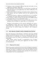
These delays, which are compared in Figure 3.7 to the delays experienced with ADSL
and UMTS, are tolerable if a large chunk of data has to be transferred. For short and bursty
data transmissions as in a web-browsing session, however, the delay is noticeable.
UMTS solves these shortcomings as follows. In order to increase the data transmission
speed per user, UMTS increases the bandwidth per carrier frequency from 200 kHz to 5 MHz.
This approach has advantages over just adding more carriers to a data transmission which
are dispersed over the frequency band, as mobiles can be manufactured much more cheaply
when only a single frequency is used for the data transfer.
The most important improvement of UMTS is the use of a new medium access scheme
on the air interface. Instead of using a frequency and time division multiple access scheme
as GSM, UMTS uses code multiplexing to allow a single base station to communicate with
many users at the same time. This method is called code division multiple access (CDMA).
Contrary to the frequency and time multiplexing of GSM, all users communicate on the
same carrier frequency and at the same time. Before transmission, the data of a user is
multiplied by a code, which can be distinguished from codes used by other users on the
receiver side. As the data of all users is sent at the same time, the signals add up on the
Figure 3.7 Round-trip delay time of UMTS (Release 99) compared to ADSL and GPRS
134 Communication Systems for the Mobile Information Society
transmission path to the base station. The base station can then use the inverse mathematical
approach that was used by the terminal as the base station knows the code of each user.
This principle can also be described within certain boundaries with the following analogies:
•
Communication during a lecture: usually there is only one person speaking at a time
while there are many persons in the room that are just listening. The bandwidth of the
‘transmission channel’ is high as it is only used by a single person. At the same time,
however, the whispering of the students is creating a slight background noise, which has
no impact on the transmission (of the speaker) due to its low volume.
•
Communication during a party: there are again many persons in a room but this time they
all talk with each other. Although the conversations add up in the air the human ear is
still able to distinguish the different conversations from each other. Other conversations
are filtered out by the ear as unwanted background noise. The more people speak at the
same time, the higher the perceived background noise for the listeners. In order to be
understood the speakers have to reduce their talking speed. Another method for talkers
could also be to increase their volume to be able to be heard over the background noise.
This, however means, that the background noise for others increases substantially.
•
Communication in a disco: in this scenario, the background noise, i.e. the music, is very
loud and communication is no longer possible.
These scenarios are analogous to a UMTS system as follows: if there are only few users
that communicate with the base station at the same time, each user will experience only low
interference on the transmission channel. Therefore, the transmission power can be quite
low and the base station is still able to distinguish the signal from other sources. This also
means that the available bandwidth per user is high and can be used if necessary to increase
the transmission speed. If data is sent faster, the signal power needs to be increased to get a
more favorable signal-to-noise ratio. As only few users are using the transmission channel
in this scenario, increasing the transmission speed is no problem as all others are able to
compensate.
If many users communicate with a base station at the same time, all users will experience
a high background noise. This means that all users have to send at a higher power in order
to overcome the background noise. As each user in this scenario can still increase the power
level the system remains stable. This means that the transmission speed is not only limited
by the 5 MHz bandwidth of the transmission channel but also by the noise generated by other
users of the cell. While the system is still stable, it might not be possible to increase the
data transmission speed for some users that are farther away from the base station as they
cannot further increase their transmission power and thus cannot reach the signal-to-noise
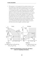
ratio required for a higher transmission speed. See Figure 3.8.
Transmission power cannot be increased indefinitely because UMTS terminals in Europe
are limited to a maximum transmission power of 0.25 watt. If the access network could not
continuously control and be aware of the power output of the mobile stations, a point would
be reached at which too many users communicate with the system. As the signals of other
users are perceived as noise from a single user’s point of view a situation could occur when
a mobile station can no longer increase its power level to get an acceptable signal-to-noise
ratio. On the contrary, if a user is close to a base station and increases its power above the
level commanded by the network, it could interfere with the signals of terminals, which are
further away and thus weaker.
Universal Mobile Telecommunications System (UMTS) 135
Figure 3.8 Simultaneous communication of several users with a base station in the uplink direction
(axis not to scale and number of users per base station is higher in a real system)
From a mathematical point of view, CDMA works as follows.
The user data bits of the individual users are not transferred directly over the air interface
but are first multiplied with a vector, which for example has a length of 128. The elements
of the resulting vector are called chips. A vector with a length of 128 has the same number
of chips. Instead of transmitting a single bit over the air interface, 128 chips are transmitted.
This is called ‘spreading’, as more information, in this example 128 times more, is sent over
the air interface compared to the transmission of the single bit. On the receiver side the
multiplication can be reversed and the 128 chips are used to deduce if the sent bit represents
a 0 or 1. Figure 3.9 shows the mathematical operations for two mobile stations that transmit
data to a single receiver (base station).
Figure 3.9 Simultaneous conversation of two users with a single base station and spreading of the
data stream
136 Communication Systems for the Mobile Information Society
The disadvantage of sending 128 chips instead of a single bit might seem quite severe
but on the other hand there are two important advantages: transmission errors that change
the values of some of the 128 chips while being sent over the air interface can easily be
detected and corrected. Even if several chips are changed due to interference the probability
of correctly identifying the original bit is still very high. As there are many 128-chip vectors,
each user can be assigned a unique vector that allows calculation of the original bit out of the
chips at the receiver side not only for a single user but also for multiple users at the same time.
3.3.1 Spreading Factor, Chip Rate, and Process Gain
The process of encoding a bit into several chips is called spreading. The spreading factor
for this operation defines how many chips are used to encode a single bit. The speed with
which the chips are transferred over the UMTS air interface is called the chip rate and is
3.84 MChips/s independent of the spreading factor.
As the chip rate is constant, increasing the spreading factor for a user means that his data
rate decreases. Besides a higher robustness against errors there are a number of other advan-
tages of a higher spreading factor: the longer the code, the more codes exist that are orthogonal
to each other. This means that more users can simultaneously use the transmission channel
than compared to a system in which only shorter spreading factors are used. As more users
generate more noise, it is likely that the error rate increases at the receiver side. However, as
more chips are used per bit, a higher error rate can be accepted than for a smaller spreading
factor. This in turn means that a lower signal-to-noise ratio is required for a proper recep-
tion and thus the transmission power can be reduced if the number of users in a cell is
low. As less power is required for a slower transmission, it can also be said that a higher
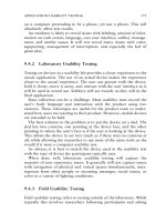
spreading factor increases the gain of the spreading process (processing gain). See Figure 3.10.
If shorter codes are used, i.e. fewer chips per bit, the transmission speed per user increases.
However, there are two disadvantages: due to the shorter codes, fewer people can communi-
cate with a single base station at the same time. With a code length of eight (spreading factor
8), which corresponds to a user data rate of 384 kbit/s in the downlink direction, only eight
users can communicate at this speed. With a code length of 256 on the other hand, 256 users
Figure 3.10 Relation between spreading factor, chip rate, processing gain, and available bandwidth
per user
Universal Mobile Telecommunications System (UMTS) 137
can communicate at the same time with the base station although the transmission speed
is a lot slower. Due to the shorter spreading code, the processing gain also decreases. This
means that the power level of each user has to increase in order to minimize transmission
errors.
3.3.2 The OVSF Code Tree
The UMTS air interface uses a constant chip rate of 3.84 MChips/s. If the spreading factor
is also constant, all users of a cell have to communicate with the network at the same speed.
This is not desired because a single cell has to support many users with many different
applications simultaneously. While some users may want to simply make voice calls, which
require only a small bandwidth, other users at the same time might want to place video calls,
watch some mobile TV (video streaming), or start a web-surfing session. All these services
require much higher bandwidths and thus using the same spreading factor for all connections
is not practical.
The solution to this problem is called orthogonal variable spreading factors (OVSF). While
in the previous mathematical representation the spreading factors of both users were of the
same length, it is possible to assign different code lengths to different users at the same time
with the following approach.
As the codes of different lengths also have to be orthogonal to each other, the codes need
to fulfill the following condition as shown in Figure 3.11: in the simplest case (C1,1), the
vector is one dimensional. On the next level with two chips, four vectors are possible of
C
1,1
=
(1)
C
2,1
= (1,1)
C
2,1
=
(1,–1)
C
4,1
=
(1,1,1,1) C
4,2
=
(1,1,–1,–1) C
4,3
=
(1,–1,1,–1) C
4,4
=
(1,–1,–1,1)
SF
= 2
SF
= 4
SF
= 8
SF
= 16
SF = 512
Sub-tree cannot be used if
the code above has been
allocated to a subscriber
C
8,2
= …
…
Figure 3.11 The OVSF code tree
138 Communication Systems for the Mobile Information Society
which two are orthogonal to each other (C2,1 and C2,2). On the third level with four chips,
there are 16 possible vector combinations and four that are orthogonal to each other. The
tree which continues to grow for SF 8, 16, 32, etc., shows that the higher the spreading
factor, the more subscribers can communicate with a cell at the same time.
If a terminal, for example, uses a spreading factor of eight, all longer codes of the same
branch can no longer be used. This is due to the fact that the codes below are not orthogonal
to the code on the higher level. As the tree offers seven other SF 8 spreading factors, it
is still possible for other users to code with higher spreading factors from one of the other
vertical branches of the code tree. It is up to the network to decide how many codes are
used from each level of the tree. Thus the network has the ability to react dynamically to
different usage scenarios.
Table 3.1 shows the spreading factors in the downlink direction (from the Node-B to the
terminal) as they are used in a real system. The raw data rate is the number of bits transferred
per second. The user data rate results from the raw data rate after removal of extra bits, which
are used for channel coding that is necessary for error detection and correction, signaling
data, and channel control.
3.3.3 Scrambling in the Uplink and Downlink Directions
By using OVSF codes, the data rate can be adapted for each user individually while still
being able to differentiate the data streams with different speeds. Some of the OVSF codes
are quite uniform. C(256,1) for example only comprises ‘1’ chips. This creates a problem
further down the processing chain because the modulation of long sequences that never
change their value would result into a very uneven spectral distribution. To counter this
effect the chip stream that results from the spreading process is scrambled. This is done by
multiplying the chip stream as shown in Figure 3.12 with a pseudo random code called the
scrambling code. The chip rate of 3.84 MChips/s is not changed by the process.
In the downlink direction the scrambling code is also used to enable the terminal to
differentiate between base stations. This is necessary as all base stations of a network transmit
on the same frequency. In some cases mobile operators have bought a license for more
than a single UMTS frequency. However, this was done to increase the capacity in densely
populated areas and not to make it easier for mobile stations to distinguish between different
base stations. The use of a unique scrambling code per base station is also necessary to
Table 3.1 Spreading factors and data rates
Spreading factor
(downlink)
Raw data rate
(kbit/s)
User data rate
(kbit/s)
Application
8 960 384 Packet data
16 480 128 Packet data
32 240 64 Packet data and video telephony
64 120 32 Packet data
128 60 122 Voice and packet data
256 30 515 Voice
512 15 17 Signaling, SMS, location update…
Universal Mobile Telecommunications System (UMTS) 139
Spreading e.g. with
OVSF SF = 8–512
Scrambling
RF-modulator
Chip rate:
3.84 MChips/s
Data rate:
e.g. 64 kbit/s
(+ Channel
coding)
Chip rate:
3.84 MChips/s
User data
Figure 3.12 Spreading and scrambling
allow a base station to use the complete code tree instead of sharing it with the neighboring
cells. This means that in the downlink direction, capacity is mainly limited by the number
of available codes from the code tree as well as the interference of other base stations as
experienced by the user equipment.
In the uplink direction each terminal is assigned its own scrambling code. Therefore, each
terminal could theoretically use all codes of the code tree. This means that in the uplink
direction the system is not limited by the number of codes but by the maximum transmitting
power of the user equipment and by the interference that is created by other terminals in the
current and neighboring cells.
Another reason for using a unique scrambling code per terminal in the uplink direction is
the signal propagation delays. As different users have different distances to a base station the
signals take different amounts of time to arrive. In the GSM radio network this was solved
by controlling the timing advance (see Section 1.7.4). The use of a timing advance, however,
is not possible in the UMTS radio network due to the soft handover state (see Section 3.7.1)
in which the user equipment communicates with several base stations at the same time.
As the user equipment is at a different distance to each base station it communicates with
simultaneously, it is not possible to synchronize the mobile station to all base stations due
to the different signal propagation delays. Therefore, if no scrambling code was used the
mathematical equation shown in Figure 3.9 would no longer work as the chips of the different
senders would be out of phase with each other and the result of the equation would change.
See Table 3.2.
3.3.4 UMTS Frequency and Cell Planning
As all cells in a UMTS radio network can use the same frequency, the frequency plan is
greatly simplified compared to a GSM radio access network. While it was of paramount
importance in a GSM system to ensure that neighboring cells use different frequencies, it
is quite the reverse in UMTS as all neighboring stations use the same frequency. This is
possible due to the CDMA characteristics, which were described in the previous sections.
While a thorough and dynamic frequency plan is indispensable for GSM, no frequency
adaptations are necessary for new UMTS cells. If a new cell is installed in an area that
140 Communication Systems for the Mobile Information Society
Table 3.2 Spreading and scrambling in the uplink and downlink directions
Downlink Uplink
Spreading Addressing of different users Controls the individual data rate
for each userControls the individual data rate
for each user
Scrambling Ensures consistent spectral
distribution
Ensures consistent spectral
distribution
Used by the mobile terminal to
differentiate base stations
Differentiates users
Removes the need for a timing
advance by preserving
orthogonal nature of the codes
Necessary for soft handover
is already covered by other cells in order to increase the bandwidth the most impor-
tant task in a UMTS network is to decrease the transmission power of the neighboring
cells.
In GSM and UMTS radio networks alike it is necessary to properly define and manage
the relationships between the neighboring cells. Incorrectly defined neighboring cells are
not immediately visible but create difficulties for handovers (see Section 3.7.1) and cell
reselections (see Section 3.7.2) of moving subscribers later on. Properly executed cell changes
and handovers also improve the overall capacity of the system as they minimize interference
of mobiles that stay in cells that are no longer suitable for them.
3.3.5 The Near-Far Effect and Cell Breathing
As all users transmit on the same frequency, interference is the most limiting factor for the
UMTS radio network. The following two phenomena are a direct result of the interference
problem.
In order to keep the interference at a minimum it is important to have a precise and fast
power control. Users that are further away from the base station have to send with more
power than those closer to the base station as the signal gets weaker the further it has to
travel. This is called the near-far effect. Even small changes of the position of the user like
moving from a free line of sight to a base station behind a wall or tree has a huge influence
on the necessary transmission power. The importance of efficient power control for UMTS
is also shown by the fact that the network can instruct each handset 1500 times per second
to adapt its transmission power. A beneficial side effect of this for the mobile station is an
increased operating time, which is very important for most devices as the battery capacity is
quite limited.
Note: GSM also controls the transmission power of the handsets. The control cycle,
however, is in the order of a second as interference in GSM is less critical then in UMTS.
Therefore, power control is mostly beneficial to increase the operating time of the user
equipment.
Universal Mobile Telecommunications System (UMTS) 141
The dependency on low interference for each user also creates another unwanted side
effect. Let us assume the following situation:
1. There is a high number of users in the coverage area of a base station and the users are
dispersed at various distances from the center of the cell.
2. Because of interference the most distant user needs to transmit at the highest possible
power.
3. An additional user who is located at a medium range from the center of the cell tries to
establish a connection to the network for a data transfer.
In this situation the following things can happen: if the network accepts the connection
request the interference level for all users will rise in the cell. All users thus have to increase
their transmission power accordingly. The user at the border of the cell, however, already
transmits at its maximum power and thus can no longer increase the power level. As a result
his signal cannot be correctly decoded and the connection is broken. Seen from outside the
system this means that the geographical area the cell can cover is reduced as the most distant
user cannot communicate with the cell. The phenomenon is called cell breathing due to the
fact that the cell expands and shrinks like a human lung, which increases and decreases its
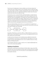
size while breathing. See Figure 3.13.
To avoid this effect the network constantly controls the signal-to-noise ratio of all active
users. By actively controlling the transmission power of each user the network is aware of
the impact an additional user would have on the overall situation of the cell. Therefore, the
network has the possibility of rejecting a new user to protect the ongoing sessions.
In order to preserve all ongoing connections and additionally allow a new user to enter
the system it is also possible to use a different strategy. The goal of this strategy is to
Two subscribers of a cell one of them
close to the cell edge sending with its
maximum possible power level
A third subscriber would like to
communicate in the cell. This poses
a problem for the second subscriber
as he can’t increase the power outpu
t
to counter the additional interference
Figure 3.13 Cell breathing
142 Communication Systems for the Mobile Information Society
reduce the interference to a level that allows all users including the prospective new one
to communicate. This can be done in a number of ways. One way is to assign longer
spreading codes to already established channels. As has been shown in Section 3.3.2, it is
possible for terminals to reduce their transmission power by using longer spreading codes.
This in turn reduces the interference for all other users. The disadvantage of using longer
spreading codes is of course a reduction in the maximum transmission speed for some users.
As not all connections might be impacted, there are again a number of possibilities for the
selection process. Users could for example be assigned to different user classes. Changing
spreading factors could then be done only for users of a lower user class who pay less
for their subscription than others. It can also be imagined that the network already starts
a congestion defense mechanism at a certain load threshold before the system gets into an
overload situation. Once the threshold is reached, the network could then for example only
assign short spreading factors to users with a higher priority subscription while the system
load is above the threshold.
Besides cell breathing there are further interference scenarios. As already mentioned, it is
necessary to increase the transmission power if the spreading factor is decreased in order to
ensure a proper reception. Therefore, the maximum distance a user can be from the center of
the cell also depends on the spreading factor. If a user roams between two cells it is possible
that the current spreading factor would not allow data to be transferred as reliably as before
due to the interference encountered at the cell edge. A lower spreading factor, however,
would still allow a reliable data transfer. How this and similar scenarios at cell edges are
resolved depends on the vendor’s equipment and the parameter settings of the operator.
As in other areas, the UMTS standard does not dictate a specific solution to these issues.
Therefore, network vendors that have implemented clever solutions can gain a competitive
advantage.
3.3.6 Advantages of the UMTS Radio Network Compared to GSM
While in the previous paragraphs the basic properties and methods of the UMTS W-CDMA
air interface have been introduced, the following paragraph describes how this new air
interface overcomes the limitations of GSM/GPRS.
One of the main reasons for the long delay times of GPRS are the constant reassignments
of resources for bursty data traffic. UMTS solves this issue by assigning a dedicated channel
not only for voice calls but also for packet data connections. The channel remains dedicated
to the user even if there is no data transferred for some time. A downside of this approach,
however, is that the spreading code is not available to other users. Due to the fact that
only control information is sent over the established channel during times of inactivity, the
interference level for other users decreases. As a result, only a little of the overall capacity
of a cell is lost by keeping the spreading code assigned to a dormant user for some time. In
a well-implemented network, from a subscriber’s point of view, the spreading code should
only be freed up for use by someone else if the session remains dormant for a prolonged
amount of time. Once the system decides to reassign the code to someone else, it can assign
a higher spreading factor to the dormant user of which a greater number exists per cell.
If the user resumes data transmission, there is no delay as a dedicated channel still exists.
If required, the bandwidth for the user can be increased again quite quickly by assigning
a code with a shorter spreading factor. The subscriber, however, does not have to wait
Universal Mobile Telecommunications System (UMTS) 143
for this as in the meantime data transfer is possible over the existing channel. If the user
remains dormant for an even longer time, the network might then go ahead and remove
all resources on the air interface without cutting the logical connection. This saves further
resources and also has a positive effect on the overall operating time of a terminal as it
consumes less energy if the channel is released. The disadvantage of this approach is a longer
reaction time once the user wants to resume the data transfer. In the uplink direction, the
same methods are applied. It should be noted though that while the user is assigned a code,
the mobile station will be constantly transmitting in the uplink direction. The transmission
power will be lower while no user data is sent but the mobile station keeps sending power
control and signal quality measurement results to the network. This is why it is beneficial
to move the user into the Cell-FACH (forward access channel) state after a longer period
of inactivity. In this state, no control information is sent from the user equipment to the
network and no dedicated channel is assigned to the connection. The different connection
states are described in more detail in Section 3.5.4. Furthermore, an analysis of how oper-
ational networks handle the code and state management of a packet call can be found in
Section 3.9.2.
The assignment of dedicated channels for both circuit- and packet-switched connections
in UMTS has a big advantage for mobile users compared to GPRS. In the GPRS network,
the mobile station is solely responsible for performing a cell change. Once the cell has
been changed, the mobile first needs to listen to the broadcast channel before the connec-
tion to the network can be re-established. In a practical environment, a cell change thus
interrupts an ongoing data transmission for about one to three seconds. A handover, which
is controlled by the network and thus results in no or only a minimal interruption of the
data transmission, has not been foreseen for GPRS. Thus, GPRS users frequently experience
interruptions of the data transmission during cell changes while traveling in cars or trains.
With UMTS, however, there are no interruptions of an ongoing data transfer when changing
cells due to a process called ‘soft handover’, which makes data transfers while on the
move much more efficient. Furthermore, applications like voice over IP or video telephony
on the move are thus also possible as they no longer experience interruptions during cell
changes.
Another problem of GSM is the historical dimensioning of the transmission channel for
narrow band voice telephony. This limitation was overcome for GPRS by combining several
timeslots for the time of the data transfer. The maximum possible data rate, however, is
still limited by the overall capacity of the 200 kHz carrier. For UMTS, high bandwidth
applications were taken into consideration for the overall system design from the beginning.
Due to this, a maximum data transfer rate of 384 kbit/s can be achieved with spreading
factor eight in the downlink direction. In the uplink direction, data rates of 64 and 128 kbit/s
can be reached, which are not as fast as in the downlink direction mainly due to the lower
transmission power and omni-directional antenna design. These speeds are suitable for fast
web surfing as well as for applications like voice over IP and video telephony.
UMTS also enables circuit-switched 64 kbit/s data connections in the up- and downlink
directions. This speed is equal to an ISDN connection in the fixed-line network and is mostly
used for video telephony between UMTS users.
UMTS can also react very flexibly to the current signal quality of the user. If the user
moves away from the center of the cell, the network can react by increasing the spreading
factor of the connection. This reduces the maximum transmission speed of the channel,
which is usually preferred compared to losing the connection entirely.
144 Communication Systems for the Mobile Information Society
The UMTS network is also able to react very flexibly to changing load conditions on
the air interface. If the overall interference reaches an upper limit, or if a cell runs out of
available codes due to a high number of users in the cell, the network can react and assign
longer spreading factors to new or ongoing connections.
3.4 UMTS Channel Structure on the Air Interface
3.4.1 User Plane and Control Plane
GSM, UMTS, and other modern fixed and wireless communication systems differentiate
between two kinds of data flows. In UMTS, these are also separated into two different planes.
Data flowing in the user plane is data that is directly and transparently exchanged between
the users of a connection like voice data or IP packets. The control plane is responsible for
all signaling data that is exchanged between the users and the network. The control plane is
thus used for signaling data to exchange messages for call establishment or messages, e.g.
for a location update. Figure 3.14 shows the separation of user and control plane as well as
some examples for protocols that are used in the different planes.
3.4.2 Common and Dedicated Channels
Both user plane data and control plane data are transferred over the UMTS air interface in
so-called ‘channels’. Three different kinds of channels exist.
Dedicated channels: these channels transfer data for a single user. A dedicated channel is
used for example for a voice connection, for IP packets between the user and the network
or a location update message.
The counterpart to a dedicated channel is a common channel. Data transferred in common
channels is destined for all users of a cell. An example of this type of channel is the broadcast
Core network
Radio network
(UTRAN)
Terminal
User planeControl plane
RRC messages
End-to-end beare
r
Voice or
IP packets
CC, MM
GMM/SM
Figure 3.14 User and control planes
Universal Mobile Telecommunications System (UMTS) 145
channel which transmits general information about the network for all users of a cell such
as to which network the cell belongs to, current state of the network, etc. Common channels
can also be used by several devices for the transfer of user data. In such a case, each device
filters out its packets from the stream broadcast over the common channel and only forwards
these to higher layers of the protocol stack.
Very similar to common channels are shared channels. These channels are not monitored
by all devices but only by those which have been instructed by the network to do so. An
example of such a channel is the high speed downlink shared channel of HSDPA (see
Section 3.10).
3.4.3 Logical, Transport, and Physical Channels
In order to separate the physical properties of the air interface from the logical data trans-
mission, the UMTS design introduces three different channel layers. Figure 3.15 shows the
channels on different layers in the downlink direction while Figure 3.16 does the same for
the uplink channels.
Logical Channels
The topmost channel layer is formed by the logical channels. Logical channels are used
to separate different kinds of data flows that have to be transferred over the air interface.
Figure 3.15 Logical, transport, and physical channels in the downlink direction
Figure 3.16 Logical, transport, and physical channels in the uplink direction
146 Communication Systems for the Mobile Information Society
The channels contain no information on how the data is later transmitted over the air. The
UMTS standards define the following logical channels:
•
The BCCH (broadcast control channel): this channel is monitored by all terminals in idle
state to receive general system information from the network. Information distributed via
this channel for example includes how the network can be accessed, which codes are used
by the neighboring cells, the LAC, the cell ID, and many other parameters. The parameters
are further grouped into system information block (SIB) messages to help the terminal
decode the information and to save air interface bandwidth. A detailed description of the
messages and parameters can be found in 3GPP 25.331, chapter 10.2.48.8 [1].
•
The PCCH (paging control channel): this channel is used to inform users of incoming calls
or SMS messages. Paging messages are also used for packet-switched calls if new data
arrives from the network once all physical resources (channels) for a subscriber have been
released due to a long period of inactivity. If the terminal receives a paging message it has
to first report its current serving cell to the network. The network will then re-establish
a logical RRC connection with the terminal and the data waiting in the network is then
delivered to the terminal.
•
The CCCH (common control channel): this channel is used for all messages from and
to individual terminals (bi-directional) that want to establish a new connection with the
network. This is necessary for example if a user wants to make a phone call, send an
SMS, or to establish a channel for packet-switched data transmission.
•
The DCCH (dedicated control channel): while the three channels described above are
common channels observed by many terminals in the cell, a DCCH only transports data
for a single subscriber. A DCCH is used for example to transport messages for the
mobility management (MM) and call control (CC) protocols for circuit-switched services,
packet mobility management (PMM) and session management (SM) messages for packet-
switched services from and to the MSC and SGSN. These protocols are described in more
detail in Sections 3.6 and 3.7.
•
The DTCH (dedicated traffic channel): this channel is used for user data transfer between
the network and a single user. User data can for example be a digitized voice signal or
IP packets of a packet-switched connection. If a dedicated logical channel carries a voice
call, it is mandatory to map this channel to a dedicated physical channel. If the dedicated
logical channel carries data of a packet-switched connection, however, it is also possible
to map the dedicated logical connection onto a common or shared physical channel. As
can be seen in Figure 3.15 it is thus possible to map a DTCH not only on a dedicated
transport and physical channel but also on a common/shared channel.
Note: In UMTS Release 99 most IP packet-switched connections will always be carried
over a dedicated physical channel. By using this approach individual user speeds of up to
384 kbit/s in the downlink direction are possible. Common/shared physical channels (e.g.
the FACH which is introduced below) are only used if the user has been inactive for a
long time or if the user only sends or receives small amounts of data infrequently.
•
The CTCH (common traffic channel): this channel is used for cell broadcast information.
In GSM, the same mechanism is used, for example, by Vodafone in Germany to inform
subscribers of fixed-line phone network area codes which are used around the current cell
that can be called from the mobile phone for a cheaper tariff.
Universal Mobile Telecommunications System (UMTS) 147
Transport Channels
Transport channels prepare downlink data frames for transmission over the air interface by
splitting them into smaller parts, which are encapsulated into RLC/MAC frames that are
more suitable for the transmission over the air interface. The RLC/MAC header, which is
put in front of each frame, contains among other things the following information:
•
length of the frame (10, 20, 40, or 80 ms);
•
type of integrity checking mechanism (CRC checksum);
•
channel coding format for error detection and correction;
•
rate matching if the speed of the physical channel and the layers above do not match;
•
control information for detection of discontinuous transmission (DTX) if the other end
has no data to send at a particular time.
All of these properties are combined into a so-called transport format. The actual channel
coding, however, is only performed on the physical layer on the Node-B. This is very
important as channel coding includes the addition of error detection and correction bits to
the data stream, which can be a huge overhead. In Chapter 1, for example, the half-rate
convolutional decoder for channel coding was introduced, which practically doubles the
data rate. UMTS also makes use of this channel coder and further introduces a number of
additional ones.
Logical channels are mapped to the following transport channels:
•
The BCH (broadcast channel): transport channel variant of the logical BCCH.
•
The DCH (dedicated channel): this transport channel combines data from the logical DTCH
and the logical DCCH. The channel exists in both the uplink and downlink directions as
data is exchanged in both directions.
•
The PCH (paging channel): transport channel variant of the logical PCCH.
•
The RACH (random access channel): The bi-directional logical CCCH is called RACH
on the transport layer in the uplink direction. This channel is used by terminals to send
RRC connection request messages to the network if they wish to establish a dedicated
connection with the network (e.g. to establish a voice call). Furthermore, the channel is
used by terminals to send user packet data (in Cell-FACH state, see Section 3.5.4) if
no dedicated channel exists between the terminal and the network. It should be noted,
however, that this channel is only suitable for small amounts of data.
•
The FACH (forward access channel): this channel is used by the network to send RRC
connection setup messages to terminals which have indicated via the RACH that they
wish to establish a connection with the network. The message contains information for the
terminal on how to access the network. If the network has assigned a dedicated channel,
the message contains, for example, which spreading codes will be used in the uplink and
downlink directions. The FACH can also be used by the network to send user data to a
terminal if no dedicated channel has been allocated for a data transfer. The terminal is
then in the Cell-FACH state, which is further described in Section 3.5.4. In the uplink
direction data is transferred via the RACH.
148 Communication Systems for the Mobile Information Society
Physical Channels
Physical channels are responsible for offering a physical transmission medium for one or
more transport channels. They are also responsible for channel coding, i.e. the addition of
redundancy and error detection bits to the data stream.
The intermediate products between transport channels and physical channels are called
composite coded transport channels (CCTrCh) and are a combination of several transport
channels which are subsequently transmitted over one or more physical channels. This
intermediate step was introduced because it is not only possible to map several transport
channels onto a single physical channel (e.g. the PCH and FACH on the S-CCPCH) but it
is also possible to map several physical channels onto a single transport channel (e.g. the
DPDCH and DPCCH onto the DCH).
The following physical channels are used in a cell:
•
The P-CCPCH (primary common control physical channel): this channel is used for
distributing broadcast information in a cell.
•
The S-CCPCH (secondary common control physical channel): this channel is used to
broadcast the PCH and FACH. As the spreading factor for this channel is variable, data
rates from a few kbit/s up to several 100 kbit/s can be achieved by using spreading factors
between 4 and 256. This has been done as the FACH can not only transport channel
assignment messages to terminals, but it can also be used to transport user data for
terminals (Cell-FACH state). Due to the unpredictability of the amount of user traffic, the
operator thus has a tool to adjust the channel bandwidth depending on the traffic situation.
•
The PRACH (physical random access channel): the physical implementation of the random
access channel.
•
The AICH (acquisition indication channel): this channel is not shown in the channel
overview figures as there is no mapping of it to a transport channel. The channel is used
exclusively together with the PRACH during the connection establishment of a terminal
with the network. More about this channel and the process of establishing a connection
can be found in Section 3.4.5.
•
The DPDCH (dedicated physical data channel): this channel is the physical counterpart
of a dedicated channel to a single terminal. The channel combines user data and signaling
messages from (packet) mobility management, call control, and session management.
•
The DPCCH (dedicated physical control channel): this channel is used in addition to a
DPDCH in both the uplink and downlink directions. It contains layer 1 information such
as transmit power control (TPC) bits for adjusting the transmission power. Furthermore,
the channel is also used to transmit so-called pilot bits. These bits always have the same
value and can thus be used by the receiver to generate a channel estimation, which is used
to decode the remaining bits of the DPCCH and the DPDCH. More information about the
DPCCH can be found in 3GPP TS 25.211 chapter 5.2.1 [2].
While the separation of channels in GSM into logical and physical channels is still quite
easy to understand, the UMTS concept of logical, transport, and physical channels and the
Universal Mobile Telecommunications System (UMTS) 149
mappings between them is somewhat difficult to understand at first. Therefore, the following
list summarizes the different kinds of channels and their main tasks:
•
Logical channels: these channels describe different flows of information like user data
and signaling data. Logical channels contain no information about the characteristics of
the transmission channel.
•
Transport channels: these channels prepare data packets that are received from logical
channels for transmission over the air interface. Furthermore, this layer defines which
channel coding schemes (e.g. error correction methods) are to be applied on the physical
layer.
•
Physical channels: these channels describe how data from transport channels is sent over
the air interface and apply channel coding and decoding to the incoming data streams.
In order to get an impression of which way the different channels are used, the next
section shows how the channels are used for two different procedures:
3.4.4 Example: Network Search
When a terminal is switched on, one part of the start-up procedure is the search for available
networks. Once a suitable network has been found, the terminal performs an attach procedure.
Afterwards the terminal is known to the network and ready to accept incoming calls, short
messages, etc. When the users switches the terminal off, the current information about the
network (e.g. the frequency, scrambling code, and cell ID of the current cell) is saved to the
SIM card. This enables the terminal to skip most activities required for the network search
once it is powered on and thus substantially reduces the time it takes to find and attach to
the network again. In this example, it is assumed that the terminal has no or only invalid
information about the last used cell when it is powered on. This can be the case if the SIM
card is used for the first time or if the cell for which information was stored on the SIM
card is not found.
As in all communication systems it is also necessary in UMTS to synchronize the termi-
nals with the network. Without correct synchronization it is not possible to send an RRC
connection request message at the correct time or to detect the beginning of an incoming
data frame. Therefore, the terminal’s first task after power on is to synchronize to the cells
of the networks around it. This is done by searching all frequency bands assigned to UMTS
for primary synchronization channels (P-SCH). As can be seen in Figure 3.17, a UMTS data
frame consists of 15 slots in which 2560 chips per slot are usually transported. On the P-SCH
only the first 256 chips per slot are sent and all base stations use the same code. If several
signals (originating from several base stations) are detected by the mobile at different times
due to the different distances of the terminal to the various cells, the terminal synchronizes
to the timing of the burst with the best signal quality.
Once a P-SCH is found the terminal is synchronized to the beginning of a slot. In the next
step the terminal then has to synchronize itself with the beginning of a frame. To do this
the terminal will search for the secondary synchronization channel (S-SCH). Again only 256
chips per slot are sent on this channel. However, on this channel each slot has a different
chip pattern. As the patterns and the order of the patterns are known, the terminal is able to
determine the slot that will contain the beginning of a frame.
150 Communication Systems for the Mobile Information Society
1. P-SCH
Unsynchronized start of the
network search procedure
2. S-SCH
Beginning of the frame found,
UE und UTRAN are synchronized
1 Slot = 2560 chips
15 slots = 1 frame = 10 ms
256 chips
2560 – 256 chips = 2304 chips,
SF 256 = 9 bits on the I and Q path.
Together: 18 bits per slot on the
P-CCPCH. Resulting data rate: 27 kbit/s.
4. P-CCPCH
3. CPICH
Primary scrambling code found
P-CCPCH can now be decoded
8 possible
codes
64 possible
combinations
Figure 3.17 Network search after the terminal is switched on
If an operator only has a license for a single channel, all cells of the network operator
send on the same frequency. The only way to distinguish them from each other is by using a
different scrambling code for each cell. The scrambling code is used to encode all downlink
channels of a cell including the P-CCPCH, which contains the system broadcast information.
The next step of the process is therefore to determine the primary scrambling code of the
selected cell. The first part of this process was already started with the correct identification
of the S-SCH and the chip pattern. Altogether, 64 different S-SCH chip patterns are specified
in the standard. This means that in theory the terminal could distinguish up to 64 individual
cells at its current location. In an operational network, however, it is very unlikely that
the terminal would receive more then a few cells at a time. In order to determine the
primary scrambling code the terminal then decodes the common pilot channel (CPICH),
which broadcasts another known chip pattern. Eight possible scrambling codes are assigned
to each of the 64 chip patterns, which can be found on the S-SCH. In order to find out which
code is used by the cell out of the eight scrambling codes for all other channels, the terminal
now applies each of the eight possible codes on the scrambled chip sequence and compares
the result to the chip pattern that is expected to be broadcast on the CPICH. As only one of
the scrambling codes will yield the correct chip pattern the terminal can stop the procedure
as soon as it has found the correct one.
Once the primary scrambling code has been found by using the CPICH the terminal can
now read the system information of the cell which is broadcast via the P-CCPCH. The
P-CCPCH is always encoded with spreading code C256,1 with a spreading factor of 256
which is easy to find by the mobile even under difficult radio conditions. Only after having
Universal Mobile Telecommunications System (UMTS) 151
deciphered the information which is broadcast on this channel is the mobile aware of which
network the cell belongs to. The following list shows some parameters that are broadcast on
the P-CCPCH:
•
The identity of the network the cell belongs to (MCC/MNC), location area (LAC) and
cell-ID.
•
Cell access restrictions, i.e. which groups of subscribers are allowed to communicate with
the cell. Usually all subscribers are allowed to communicate with a cell. Only under certain
conditions will the network operator choose to temporarily restrict access to parts of the
network for some subscribers. This can help during catastrophic events to allow important
users of the network like police, doctors, etc. to communicate with facilities such as hospitals
etc. Without access restrictions, cells quickly overload during such events as the number
of call attempts of normal users increase dramatically and can thus delay important calls.
•
Primary scrambling codes and frequencies of neighboring cells. As described above the
frequencies of the other cells in the area are usually the same as the frequency of the current
cell. Only in areas of very high usage might operators deploy cells in other frequency
bands to increase the overall available bandwidth. Both scrambling codes and frequencies
of neighboring cells are needed by the mobile to be able to easily find and measure the
reception quality of other cells while they are in idle mode for cell reselection purposes.
•
Frequency information of neighboring GSM cells. This information is used by the mobile
to be able to reselect a GSM cell if the signal quality of the current cell deteriorates and
no suitable neighboring UMTS cell can be received.
•
Parameters that influence the cell reselection algorithm. This way the network is able to
instruct the terminal to prefer some cells over others.
•
Maximum transmission power the mobile is allowed to use when sending a message on
the RACH.
•
Information about the configuration of the PRACH and S-CCPCH which transport the
RACH and FACH respectively. This is necessary because some parameters, such as the
spreading factor, are variable in order to allow the operator to control the bandwidth of
these channels. This is quite important as they do not only transport signaling information
but can also transport user data as will be further described below.
If the cell belongs to the network the terminal wants to attach to, the next step in the
process is to connect to the network by performing a circuit-switched location update, or
a GPRS attach, or both. These procedures use the higher protocol layers of the mobility
management and packet mobility management respectively which are also used in GSM and
GPRS. For UMTS both protocol stacks were only slightly adapted. Further information on
these procedures can be found in Sections 1.8.1 and 2.7.1.
3.4.5 Example: Initial Network Access Procedure
If the terminal is in idle state and wants to establish a connection with the network, it has to
perform an initial network access procedure. This may be done for the following reasons:
•
To perform a location update.
•
For a mobile originated call.
152 Communication Systems for the Mobile Information Society
•
To react to a paging message.
•
To start a data session (PDP context activation).
•
To access the network during an ongoing data session for which the physical air interface
connection was released by the network due to long inactivity.
For all the above scenarios, the terminal needs to access the network to request a connection
over which further signaling messages can be exchanged. As can be seen in Figure 3.18,
the terminal starts the initial network access procedure by sending several preambles with a
length of 4096 chips. The time required to transmit the 4096 chips is exactly one millisecond.
If the terminal receives no answer from the network it increases the transmission power and
repeats the request. The terminal keeps increasing the transmission power for the preambles
until a response is received or the maximum transmission power and number of retries have
been reached without a response. This is necessary as the terminal does not know which
transmission power level is sufficient to access the network. Thus the power level is very low
at the beginning which on the one hand creates only low interference for other subscribers in
Figure 3.18 Initial network access procedure (RRC connection setup) as described in 3GPP TS
25.931 [3]