MANAGING POWER ELECTRONICS VLSl and DSP-Driven Computer Systems phần 4 pot
Bạn đang xem bản rút gọn của tài liệu. Xem và tải ngay bản đầy đủ của tài liệu tại đây (2.36 MB, 41 trang )
102
Chapter
4
DC-DC Conversion Architectures
board level design. The digitalization of power is progressing in each of
these domains at different speeds, which causes much confusion.
Digital Power Chip Design
In recent years
a
number of startups have tried to crack the computing
market space at the chip level with digital implementations of the tradi-
tional analog PWM modulator design, without much success. These
implementations have found some space in high-end server blades appli-
cations that are low volume and tolerate higher cost.
In handsets, the increase in power levels is due to packing more ele-
mentary building blocks on-die. Such elementary building blocks have rel-
atively low power consumption by themselves, but in large numbers add
up to
a
considerable amount
of
power. The most complex power manage-
ment units (PMUs) built today clearly show that LDOs and switchers
remain primarily analog. On top of traditional analog,
a
good dose
of
digi-
tal is needed for communications and sequencing, and is implemented
with architectures ranging from state machines to microcontrollers.
Digital Power
IC
Processes
As far
as
integrated circuits are concerned, the leading edge of the analog
world long ago moved from pure analog to
mixed
analog and digital.
Every
VRM
chip marries an on-die Digital to Analog Converter (DAC) to
an
analog switching regulator; the same way every
PMU
mixes analog and
digital blocks. The move
to
mixed signal-the combination
of
analog and
digital
on
the die-is
a
revolution that began around 1980. It started tenta-
tively within the bipolar world with Integrated Injection Logic (I2L) logic
gates and then fully blossomed with bipolar, CMOS, and DMOS (BCD)
mono1
i
thic processes.
Today, the leading monolithic power companies have BCD mixed sig-
nal processes. These companies-as leaders often do-position them-
selves as solution-oriented, utilizing the most appropriate process,
components, and techniques for the task at hand.
BCD processes can use bipolar for precision, CMOS for signal den-
sity, and DMOS for power density. Leading BCD is today in its
7‘h
gener-
ation at 0.18 pm and soon it will be at 0.12 pm (BCD
VIII):
this is only
two nodes away from the CPU roadmap at 0.65 nm by the end of 2005.
Still, these companies understand the trade-off in terms of mask count and
cost and, therefore, keep alive simpler or “traditional” analog processes
that
in
specific applications-particularly single functional building
blocks-may result in more cost-effective designs.
Digital
Power
103
Board-Level Digital Power
Telecom and Datacom applications like
Point
Of
Loud
(POL) are the areas
where digital power may find the best niche. (Digital power in this case
refers to power regulation equipped with
a
communication bus that allows
for flexible set-output voltage, frequency compensation type, etc.) Leading
power supply companies are battling for dominance of this new market.
Conclusion
At the board level, digital power seems
to
have found
a
hot niche in POL
applications. Digital implementation of analog algorithms in silicon makes
sense is some cases, like providing silicon
in
support
of
digital POL
power, while in others it does not. The digitalization
of
power happened
twenty years ago with BCD processes; today it is happening
in
the high-
performance niches of computing power at the chip architecture level, and
it will probably happen
soon
at the board level with POLS. As the saying
goes, the next big thingdigital power
in
this instance-is already here. It
is just not uniformly distributed. Perhaps more importantly
for
IC compa-
nies,
a
good process portfolio, which includes processes like BCD, takes
us beyond the debate
of
digital versus analog and allows
us
to focus on
solutions.
Fast Switchmode Regulators and Digital Control
The bulk of the CPU power regulation volumes are in the PC motherboard
market,
a
fiercely competitive market dominated by the Taiwanese
motherboard manufacturers operating on a relatively short-term horizon
and driven by cost. Accordingly, these motherboards have the lowest pos-
sible bill of materials. It follows that the “sweet spot” for power is
a
volt-
age regulator built around some very resilient technologies based on the
buck converter, which continues to reinvent itself (from buck
to
sync buck
to
multiphase
to
.)
and thus far defies any new proposed architecture, and
the
electrolytic capacitor, which
in
its latest reincarnation, Aluminum-
Polymer, keeps the emergence of ceramic caps at bay.
More precisely, huge amounts (mF)
of
“bulk” capacitors are
employed in the design
of
buck converters to supply most
of
the energy
during transient (the time it takes the feedback loop to respond) while a
minimum number of ceramics are employed nearby the CPU socket for
quasi-instantaneous response.
Modern specifications
for
CPU regulators require operation inside
a
tight voltage band
(50
mV), while the source
of
degradation of the regulators
is the Equivalent Series Resistance (ESR, in mQ)
of
the output capacitors.
Consequently at
50
A, the tolerable
ESR
has to be
40
mV/50 A
=
1
mQ.
104
Chapter
4
DC-DC Conversion Architectures
Until now the $/mQ figure of “merit” for electrolytic remains unsur-
passed-namely the lowest-and this simple fact explains why any fast
converter technology thrown at this niche does
not
stick, despite the prom-
ise
to
eliminate the “bulky” electrolytics.
n
Discrete Duty
Ratio
t
,.
!,I
.
IN
fi
0
.
- -
-
=
DV,,
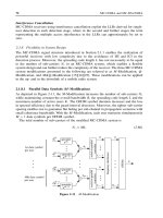
Figure
4-28
Digital power control loop.
Thanks
to
their requirement of desktop power packed inside thin form
factors, other applications that currently have less commanding volumes,
such as blade servers, offer
a
different value proposition and privilege size
over cost. This niche has become
a
playground allowing
a
few companies
to develop new and increasingly faster switchmode regulator architectures
based
on
the more expensive but slimmer ceramic capacitors. The ultimate
goal
is to break the $/mQ barrier by the design
of
switchmode controllers
and power train filters that are fast enough to respond at or above the speed
of the incoming current step di/dt (say
300
A/p).
Such
a
performance
would go beyond the elimination
of
electrolytics and would reduce drasti-
cally the number of ceramics needed on the basis of plain
ESR
calcula-
tions. The underlying architecture would then finally defeat the
established technology, with the entire regulation market being the prize.
Fairchild
is
actively researching this field.
Digital
Power
105
Digital switchmode control is a fledgling architecture testing itself
against the abatement of the $/mQ barrier. In the process, digital control is
regularly touted as an “inherently fast” technology. As conventional digital
algorithms are sequential
in
nature, requiring several clock cycles to exe-
cute an instruction, there is nothing inherently fast about them. PWM digi-
tal control is all about going beyond the CPU’s,
or
even the DSP’s
architectures, toward hard-wired logic that can respond at the speed of the
process technology. Analog techniques, which are at the same process
generation level, should be at least as fast.
Accordingly
it
is likely that at the core
of
future fast controllers, we
will find a fast analog cell, may it be a “fast clamp,” transient suppressor,
or something similar. Around this fast cell we may find all kinds of bells
and whistles, some digital and some analog.
What we need arefusr architectures that deal effectively with the CPU
voltage regulation-the rest is optional.
This Page Intentionally Left Blank
5.1
Offline Power Architectures
Introduction
System
On
u
Chip
(SOC) companies are claiming that the entire signal
path (digital
+
analog
+
memory) and even a full
GSM
system-includ-
ing power management-will be integrated in the next few years. How-
ever, the reality is that this up-integration march, fueled by nano-scale
lithography (minimum features less than
100
nm), ends up defining the
product’s own technology boundaries: the higher the number of transis-
tors on a chip, the lower their voltage and the more fragile their technol-
ogy. At the
0.13
pm juncture, for example, the SOC processes work at
voltages in the range of
1
V-2
V!
At the other end of the spectrum are the power chip companies cre-
ating technologies to deal with high voltages and high currents. Drawing
power from the AC line down to an intermediate bus voltage requires
robust devices capable of sustaining several hundred volts at several
amperes. At the same time, the conversion from bus voltage to final load
often requires low voltages at hundreds of amperes of current.
The way power conversion requirements are met in a
PC
applica-
tion, from line
Power Fuctor Correction
(PFC) to intermediate bus volt-
age out of the silver box, down to the popular low voltages on the
motherboard, nicely illustrates the new high-voltage and high-current
silicon technologies and architectures.
To
describe this evolving power
conversion technology, this chapter provides an application example of
107
108
Chapter
5
Offline (AC-DC) Architectures
Fairchild’s single chip controller, the ML4803 PFC/PWM combo, and
associated discrete transistors for the AC-DC conversion to intermediate
voltage bus. Additionally, DC-DC conversion from bus to low voltage is
demonstrated based on Fairchild’s FAN5092 buck converter. Future trends
in PFCPWM and DC-DC converters are also discussed.
Offline Control
Harmonic Limits and Power Factor Correction
Optimum conditions for power delivery from the AC line are achieved
when the electric load, a PC for example, draws current which
is
in phase
with the input voltage (AC line) and when such a current is undistorted
(sinusoidal).
To
this end, IEC 6100-2-3 is the European standard specify-
ing the harmonic limits of various equipment classes. For example, all per-
sonal computers drawing more than
75
W
must have harmonics at or
below the profile demonstrated in Figure
5-1.
With modern desktop
PSUs
drawing from 140 W
to
250 W, all PCs shipped to Europe must comply.
When it comes to compliance to IEC 6100-2-3, the rest of the world is fol-
lowing Europe’s lead at varying paces.
Figure
5-1
illustrates one aspect
of
the European specification.
Notice that the allowance grows stricter for the higher harmonics; how-
ever, these harmonics also have less energy content and are easier to filter.
According
to
the specification, the allowed harmonic current does max
out above 600 W, making it more challenging to achieve compliance at
higher power.
Power Factor (PF) is a global parameter speaking to the general qual-
ity of the power drawn from the line. It is related to the input current
Total
Harmonic Distortion
(THD) by the equation
cos
cp
PF
=
2
I/?
(1+THD)
Eq. 5-1
where
cp
is the phase shift between line voltage and drawn current. With
no
phase shift
(cp
=
0)
and
no
distortion
(THD
=
0)
it follows that
PF
=
1.
Since the numerator Icoscpl (bars indicate module or absolute value) is
bounded between zero and one and the denominator is always higher or
equal to one, it follows that
PF
5
1.
Since IEC
6
1000-3-2 specifies the harmonic components of
THD,
neither
THD
nor
PF
is a sufficient measure of performance. In reality, the
harmonic distortion parameter to measure and comply with (as per
Offline Power Architectures
109
Figure
5-1
IEC
61000-3-2 harmonic current limits.
Figure
5-1
),
and the techniques to achieve that compliance generally are
called
PFC.
It
is interesting to note that, in theory, the
COST
factor in the
PF
prod-
uct can take on negative
as
well
as
positive values. Keep in mind that
a
negative
COST
value corresponds to the situation in which the load circuit is
actually supplying real power to the line. In a rectifier circuit based on
a
diode bridge, this situation is impossible.
Harmonic Limits Compliance Constraints
The standard way to draw power from the
AC
line is via a diode bridge
rectifier directly applied across the load (Figure
5-2).
If the capacitor is not present, the voltage and current are both recti-
fied sinusoids with
no
distortion, no phase shift, and
PF
=
1
(see
Figure
5-3).
In this condition, the power delivered to the load consists of
a
waveform of double frequency, zero minimum (meaning in Figure
5-3
the
lowest part of the waveform touches the horizontal axis corresponding
to
zero power) and instantaneous value
of
P(t)=(V2/R)xsen2un=(1/2)x(V2IR)x(l
-cos2~)
Eq.5-2
110
Chapter
5
Offline (AC-DC) Architectures
"LO,
Figure
5-2
Diode bridge rectifier.
where
V
is the amplitude of the line voltage,
R
is the load, and wis the line
pulsation 2nJ withf=
SO
Hz
or
60 Hz. From Eq. 5-2 the real
or
average
power is
with a time-varying zero average pulsating power
of
PpULs
=
-(
1/2)
x
(
V2/R)
x
cos2u~ Eq.
5-4
This simple example provides a model of an ideal rectification scheme as
presented
to
the AC line. On the other hand, the scheme has no energy
storage function, and the power delivered at the output of this rectifier has
a double-line frequency component.
Continuing
in
this idealized framework, a typical load actually
requires constant (DC) power. Thus, an inherent requirement is a bulk
energy storage element, usually realized by an electrolytic capacitor, that
handles the difference in power between
P(t),
the input power, and
PAVE,
the DC output power.
Adding a small capacitor
C
(the dashed line
in
Figure
5-2)
to this
scheme will naturally smooth the voltage across the load, reducing the rip-
ple but also degrading the PFC, as the current waveform now drastically
deviates from a sinusoid (see Figure
54).
The scheme
of
Figure 5-2 (with capacitor) represents the conven-
tional, non-PFC architecture used
in
many commercial applications prior
PFC techniques are all about maintaining an input and output power
match
in
the presence of low input harmonic current content and tightly
regulated output voltage.
to IEC-6
1000-3-2.
Offline
Power
Architectures
111
"LINE, A
'LINE
0
,t
,t
PLINE
Figure
5-3
Power line
(PLINE
=
VLINE
x
ILINE)
has double frequency.
PFC
Architecture
The general architecture for PFC is shown
in
Figure
5-5.
As discussed in
the previous section,
a
PFC stage will provide a good match between line
voltage and current.
Assuming perfect balance
(PF
=
1
),
we find ourselves
in
the condition
of Figure
5-3(a)
on
the AC line side. On the rectified side, the capacitor
C
will provide a reactive power
where
VcDc
is the DC voltage across the capacitor,
VCRIppLE
is its ripple
peak, and
w
=
2#is the line voltage pulsation
cf=
50
or
60
Hz).
Notice that
PcR
is analogous to
PpuLs
in
the system from Figure 5-2 (no capacitor).
112
Chapter
5
Offline (AC-DC) Architectures
VLINE,
A
'LINE
0
,t
Figure
5-4
Capacitor
C
effect on voltage and current.
AC Line
-
Bridge
Rectified
AC
Line
-
PFC
PWM
Figure
5-5
Example
of
PFC architecture.
From Eq.
5-5,
we have
Eq.
5-6
This is
a
useful design formula showing the trade-offs between size
of
the capacitor
C
and its DC voltage and ripple values.
After the PFC stage has taken care of the line's harmonic content, the
ripple across
C
is smoothed out
by
means
of
a
DC-DC converter designed
to
have sufficient input ripple voltage rejection.
Offline Power Architectures
113
PFC and Pulse Width Modulation (PWM) Implementation
A high-level block diagram of the power conversion chain, from an AC
line to an intermediate voltage bus
Vsus
(for example, 12
V),
is shown
in
Figure
5-6.
GND
V,,
RC431A
*ENS
‘LIMIT
FAN4803
Figure
5-6
PFC and PWM chain based on FAN4803
In
Figure
5-6,
the control is based on
a
product called the FAN4803, a
very compact chip integrating two control loops
on
board. The inductor
LI,
switch
QI
(MOSFET), bulk capacitor
C,
and the diode D1 controlled
by
one half ofthe PFC/PWM controller FAN4803 (Figure
5-6),
make up
the PFC section. Next, the voltage across
C
is regulated down
to
the bus
voltage by means of
aforward
converter. The forward converter includes
switches Q2 and Q3, diodes D2-D5, passives L2 and C2, the second half
of FAN4803 for primary side control, and RC43
1
A for secondary side
control. This conversion requires electrical isolation between the high
input and the low output voltages. Isolation is accomplished via the utili-
zation of
a
transformer T
in
the forward conversion path and an opto-
coupler
H
1
1
A8 17A
in
the feedback path. Appendix
B
provides the data
sheet of FAN 4803 for more technical details.
The Controller Architecture
The FAN4803 is powered
(VCCPIN)
from the main transformer
T
via an
auxiliary secondary winding transformer (not shown) yielding a relatively
low voltage
(1
5
V).
Since every controller
I/O
pin sees voltages below
15
V,
the chip is built
in
a
low-voltage, dense BiCMOS process.
114
Chapter
5
Offline (AC-OC) Architectures
The top portion of Figure
5-7
shows the PFC control loop. The shap-
ing function is accomplished by the continuous current mode architecture,
which forces the current to follow the shape of the line voltage. In fact,
on
the small time period
(15
ps)
of
the relatively fast clock frequency
(67
kHz), when V,is roughly constant, the forced current is also constant.
However, with an input voltage
[VLINE,
Figure
5-3(a)]
crossing zero twice
per period
(100
Hz
or
120
Hz), the current in the inductor will collapse
down to zero
as
well around the rectified line voltage dips [Figure
5-3(b)],
yielding
a
current sufficiently close to the desired shape demonstrated by
the
lLoAD
waveform in Figure
5-3(b).
V,W
K'
Lc*
%EN=
Valleyileading Edge PFC Control
'
’PAM
'
RSENS
Peakrrrailing Edge PWM Control
a2
5id
m
-
-L
(
* ~~~*
RSENY
.
CLOCK
=
RESET
PWM
Figure
5-7
PFC and PWM control loops.
Offline Power Architectures
115
The very low bandwidth of the error amplifier assures control
of
the
output voltage
V,
according
to
Eq.
5-6.
The PFC and PWM functions can
be accomplished with minimum BOM when a synergistic mode
of
opera-
tion between the two sections is implemented.
As
illustrated in Figure
5-7,
the PFC section is controlled with leading edge modulation. The
MOS-
FET Q1 turns
off
on the clock edge, while turn-on, which corresponds to
the leading, or rising edge
of
the PFC square wave, is under loop control.
The PWM section is controlled with
trailing
edge
modulation. The
MOS-
FET 42 turns on the clock edge while turn-off, which corresponds to the
trailing, or falling edge
of
the PWM square wave, is under loop control.
Consequently, with synchronized clocks the two transistors never draw
currents concurrently; this further redistribution of the current results
in
minimum value of the high-voltage input capacitors.
Notice that while on the
50
Hz time scale, the waveforms look like the
ones in Figure
5-3,
on the
67
kHz (clock) scale the current will show rip-
ples due
to
the chopping effects
of
the switching regulator. In Figure
5-8,
I,
is the line current and
RAMP
is the modulator ramp voltage shown on the
67
kHz scale.
6
Near
V,"
Peak
@
120
V
RMS
Figure
5-8
Ripple
in
the line current.
Offline
Power
Silicon
All the diodes and DMOS switches between the line and the primary
of
the transformer are high voltage devices. IEC 61000-3-2 specifies
a
volt-
age limit up to 240
VRMs
for single-phase (415
VRMs
for tri-phase) power
line distribution. Accordingly, these components are able to withstand
voltages
in
the
400-
I000
V
range.
116
Chapter
5
Offline
(AC-DC)
Architectures
The boost diode
D
1
in
Figure 5-6 (RURP860) is a high-reverse volt-
age (600
V),
low-forward voltage drop
(1.5
V
at
8
A),
and ultra-fast
recovery rectifier
(fRR
<
60 ns). Its construction is shown in Figure
5-9.
The other high-voltage components in Figure 5-6 are the ultra-fast
UF4005 free-wheeling diodes, which are also able to stand
600
V,
and the
switches Q1-3 (FQP9N50). The three FQP9N50 transistors in Figure 5-6
are
500
V
N-channel enhancement MOSFETs built with planar stripe
DMOS
process, a process yielding high switching speed and very low
“on” resistance (0.73
R
at
10
V
of
Vcs).
Figure
5-10
shows a cross sec-
tion of the DMOS transistor. Finally, Figure
5-1
1
shows the picture of a
silver box.
Figure
5-9
RURP860 device cross section.
DC-DC Conversion Down to Low Voltage
The bus voltage
Vsus
(12
V
in
Figure 5-12) is distributed and reduced to
the popular 3.3
V,
2.5
V,
1.8
V,
or
VcPu
by means of switching regulators,
typically synchronous buck converters.
The FAN5092 step-down (buck) is a two-phase interleaved buck con-
verter switching up to
1
MHz
per phase, thanks to its leading edge valley
control architecture. This
IC
is able to directly drive the discrete
DMOS
transistors’ high side Q1-3 (FDB6035AL) and low side Q2-4
(FDB6676S), with integrated drivers exhibiting the lowest impedance
in
the industry (1
R).
Offline Power Architectures
117
Figure
5-1
0
Cross section
of
high voltage
DMOS
transistor.
Figure
5-1
1
Typical silver
box.
118
u1
1
I
FAN5092
R16
t12V
I
I
1
Figure
5-12
Buck converter: from
Vsus
(12
V)
down
to
3.3
V.
Future Trends
Active power correction allows us to meet easily
IEC
6100-3-2
power fac-
tor specifications but unquestionably requires a relatively heavy bill of
materials. The state-of-the-art FAN4803 helps reduce the silicon complex-
ity by integrating two controllers on the same die. These two controllers
each require a full set of passive components to do their part of the job.
Ideally, what is needed in the future
is
a true, single-stage PFCPWM con-
troller that will cut in half-or less-such complexity. Integration of the
PFCPWM function is in its infancy.
In
the future, slick new architectures
will be developed that will significantly cut the
BOM
of current
implementations.
As far as power distribution trends are concerned-DC-DC conver-
sion from
VsUs
to low voltage-the dominant architecture today is based
on the resilient, interleaved synchronous buck converter. The challenge
will be to reduce the bank of output capacitors by means of fast
architectures that can respond quickly to load changes. Advanced work in
these areas is intense, but the prize for such breakthroughs will be as big as
the entire power conversion market.
Power AC Adapter: Thermal
and
Electrical Design
119
5.2
Power
AC
Adapter: Thermal and Electrical
Design
Thermal and electrical design techniques satisfy new requirements for
AC
adapters.
Introduction: The Challenge
The power management industry makes a tremendous effort to reduce the
power dissipated by modern appliances, such as cell phones.
A
top priority
is
to
find ways
to
extend the battery life of such devices. This narrow focus
on extending untethered operation has generally limited the power man-
agement effort
to
the consumer side of the appliance, leaving the other
side-the one concerned with wall power (as in the case of a cell phone’s
AC
adapter)-relatively neglected.
Energy trends and regulations, however, such as the
EPA’s
Energy
Star@ initiative that focuses on single voltage external
AC-DC
power sup-
plies, are pushing for devices, including
AC
adapters, to meet or exceed
specific active and no-load mode requirements in order to claim compli-
ance to these initiatives and associated labels. Active mode refers to the
device-for example a charger-providing power to an active load.
A
bat-
tery under charge would be an example of active load.
A
charged battery,
even if connected to a charger, would not draw power and hence would
represent a case of no load.
In addition to being efficient in both light and full load operation, an
AC
adapter also should be as small as possible for ergonomic reasons.
Such minimum size (and maximum power density) is, in turn, defined by
the amount of heat that an
AC
adapter
cube
can dissipate while maintain-
ing reasonable temperatures.
AC Adapter Power Dissipation
The
AC
adapter brick transfers power from the line to the load with a cer-
tain efficiency such that
7
=
pOUdpIN
=
‘OUd(‘0UT
-I-
‘0)
Eq.
5-7
where
7=
efficiency
POUT
=
power delivered to the load
PIN
=
input power drawn from the
AC
line
120
Chapter
5
Offline (AC-DC) Architectures
P,
=
power dissipated inside the AC adapter
Inverting equation
Eq.
5-
I
yields the relation between dissipated
power and output power
From Eq. 5-2, we see that a switching regulator with an efficiency
of
80
percent inside the adapter will lose an amount
of
power equal to 25 per-
cent
of
the delivered power, while
a
linear regulator with
50
percent effi-
ciency will lose an amount
of
power equal
to
the one delivered
to
the load,
or half
of
the power drawn from the
line.
In this example, the linear regula-
tor dissipates four times
(1/0.25)
more power than the switching regulator
in
operation. Accordingly,
a
5
V/620 mA AC adapter delivering
a
peak
power
of
3
W
will leave, inside the adapter box, 750
mW
in switch-mode
and
3
W
in linear mode.
AC Adapter Case Temperature
AC adapters generally are required to have a max case temperature below
75°C. The heating of the case is proportional to the power dissipation and
to the ambient temperature (assume max 45°C). The amount of heat that
can be dissipated inside an enclosed box is governed by the thermodynam-
ics laws for heat convection and radiation. A simple model
of
a
plastic box
was analyzed with
ANSYS,
a
thermal simulator based
on
the finite element
method. The box had the following dimensions:
V=~XWXI=O.SX
1
x2=
I
in'
Eq.
5-9
where
h
=
height
1
=
length
w
=
width of the box, including a heat source
The box was heated with a power source and temperature profiles
were obtained for the box surface. This first-order simulation showed that
it
would take
1
W
of power dissipation inside the box to produce a peak
temperature
on
the box surface-in the spot closest to the heat source-of
roughly 74°C (45°C ambient).
Power
AC Adapter: Thermal and Electrical
Design
121
Accordingly, the switching regulator discussed previously could be
placed comfortably inside such
a
box without overheating it, while the linear
regulator would certainly exceed the maximum allowed temperature limits.
Active and No-load Operation
The ENERGY STAR specification for single voltage external AC-DC and
AC-AC power supplies took effect
on
January 1,2005.
To
meet Energy Star efficiency criteria for active mode, the 3
W
AC
adapter in our example will need to have efficiency above
60
percent. In
no-load mode the same device should consume less than 0.5
W.
State-of-
the-art designs can go as low
as
0.1
W
unloaded. However, such levels
of
performance cannot be met by traditional and generic solutions.
Development
of
a Solution
Fairchild's performance offerings for AC adapters are based on a solid,
high-voltage mixed BCD process. They offer
a
highly integrated, mono-
lithic flyback architecture that already has reduced the number of compo-
nents needed to build the AC adapter, making it a cost-effective solution
even when compared
to
dis-integrated solutions. The following will dis-
cuss what it takes to design an integrated circuit (FAN210 in Figure 5-13)
suitable to implement an AC adapter (the entire circuit in Figure 5-13 is
the
full
AC adapter) to meet light load and no-load operation.
85-265\1,,
SNUB
50
FSD210
sw
Figure
5-13
AC adapter simplified block diagram
122
Chapter
5
Offline (AC-DC) Architectures
Power dissipation at no-load has many contributors to losses, including:
IC power consumption
snub
network
transformer
bridge rectifier
All the losses associated with these elements have to be cut down sub-
stantially to stay within the allowed budget
of
0.3
W.
A flyback architecture is just fine for full load operation, but
it
would
not satisfy the no-load requirements. However, burst mode operation can
be implemented in silicon (FSD2IO)
to
achieve the no-load objective. By
virtue of gating the clock frequency and stopping
it
under light load condi-
tions, the AC adapter is able
to
operate at the nominal frequency only for
brief bursts and then “sleep” for the rest of the cycle-ffectively reducing
the frequency
of
operation down
to
a few kHz during no-load or light load
operation (Figure 5-14). As most
of
the losses listed above vary
proportionally to the frequency, burst mode reduces each substantially,
allowing the device to easily meet the desired no-load power budget.
Figure
5-14
shows the output variations around the reference voltage,
VFB
illustrates the mechanism
of
entering/exiting burst mode, and
IDS
and
VDs
illustrate the bursts of current and voltage, respectively, associated
with the DMOS integrated power transistor.
Implementation of the burst mode operation in both silicon and board
design can happen very quickly. To speed the process, Fairchild makes
available the “FPSTM Design Assistant,” a simple and effective software
design tool that is also available online
on
Fairchild’s website (see applica-
tion note AN41
37
online at
www.fairchildsemi.com
for details).
The result of the demand for better power dissipation is the Fairchild
Power Switch (FPSTM) FSD210, an off-line power switcher (see
Figure
5-1
3).
This device combines a SenseFET lateral DMOS transistor
(LDMOS) for current driving and sensing
(700
V
minimum breakdown
rating) with a voltage mode
PWM
IC-a combination that minimizes
external components, simplifies the design, and lowers power dissipation
and cost in targeted power saving or,
green mode
AC adapter applica-
tions. Figure
5-15
shows a compact traveler adapter with FSD210 cir-
cled. Appendix C provides the data sheet
of
FSD210 for more technical
details.
Power
AC
Adapter: Thermal and Electrical Design
123
Figure
5-14
Illustration
of
burst mode operation.
Figure
5-15
A
compact traveler adapter with
FDS210
circled.
124
Chapter
5
Offline (AC-DC) Architectures
Conclusion
Miniaturization trends of modern electronic appliances, and their market
diffusion by the billions, fuel
a
keen interest in more efficient designs. This
is evident by the many protocols and initiatives already in place. Power
requirements are pushing technology advancements beyond the tradi-
tional, cost-oriented model
of
minimizing the appliance’s
BOM.
To
meet
these demands,
AC
adapter performance can be adequately met with
proper thermal and electrical design techniques. Even with rising power
requirements of today’s smart phones-convergent devices that deliver all
the data voice and video features imaginable-it seems safe to predict that
the
AC
adapter will not be the bottleneck for power delivery when designs
are based on efficient switching architectures.
6.1
Power Management
of
Wireless Computing
and Communications Devices
Cellular telephone technology is one of the best success stones
of
recent
years for its ability to keep the user working untethered for the entire
day, with a single overnight recharge. The ultimate vision for this tech-
nology is the
smart
phone,
which would have the advanced functionality
of
a
handheld computing device, a digital still camera, a global position-
ing system,
a
music player,
a
portable television set,
a
mobile phone,
and more in a convergent device. Reaching such a level of functionality
without compromising the usage model will present enormous chal-
lenges as well as opportunities for the electronics industry and in partic-
ular for power management.
The Wireless Landscape
The wireless landscape is, and will remain for many years, very frag-
mented along both geographical and communications standards lines.
Three generations of digital cellular technologies-second (2G),
third (3G), and in-between (2SG)-already coexist (see Table 6-1).
Japan is ahead
of
the pack with 3G (W-CDMA and CDMA2000
flavors), while as
I
write the United States
is
building the infrastructure
to provide 2.5G technology. Europe and Asia are somewhere in
between.
125
126
Chapter
6
Power Management
of
Ultraportable Devices
Generation
Second
Twoanda
half
Table
6-1
Common Cellular Standards
Symbol
Type Description Speed
2G GSM Global System
14.4
Kbps
Mobile
Radio Service
2.5G
GPRS General Packet
25-40
KbpS
Third
Third
3G
EDGE Enhanced Data Rate
>144
Kbpsa
3G
CDMA, Wideband Code
>2
Mbps
GSM Evolution
W-CDMA Division Multiple
Access
The Japanese typically do not own home computers and rely increas-
ingly on their phones to exchange text messages as well as access email
and the Internet. If this behavior takes hold elsewhere, the future of smart
phones is assured.
The real possibility that smart phones will become the next disrupting
technology-meaning that the success of smart phones will threaten
almost every other established consumer technology, including
PCs
and
notebooks-seems to be confirmed by the recent entrance into the wireless
arena of powerful novices like Intel and Microsoft.
Power Management Technologies for Wireless
The majority of cellular and handheld devices are powered today by single
cell Lithium-Ion batteries. The wireless semiconductor smart
ICs
in
the
signal path, following an established industry-wide trend, are mostly
designed in sub-micron, low voltage, and high density processes. Conse-
quently the power management ICs are-with a few exceptions-low
voltage devices themselves, bridging the gap between the power source
voltage range
(2.7-4.2
V)
and the operational voltage of the signal
ICs
(1-3.5
V).
Such low operational voltages in conjunction with the necessity
of low quiescent currents for long standby times have established low volt-
age CMOS
(0.5
pm minimum feature at his juncture) as the process of
choice for wireless voltage regulators. Since in these applications the
space is premium, these voltage regulators come in very small packages
(see Figure 6-l), from leaded to lead-less to chip
scale
varieties.