Smart Card Handbook phần 5 pot
Bạn đang xem bản rút gọn của tài liệu. Xem và tải ngay bản đầy đủ của tài liệu tại đây (1.3 MB, 113 trang )
6.4 Data Transmission Protocols 419
Terminal
SELECT FILE [FID = '3F00']
response to SELECT FILE
Smart Card
NAD PCB LEN EDC
'00' '00'
'06í
'A2'''A4 00 00 02 3F 00
TPDU
APDU
NAD PCB LEN EDC
'00' '00' '02' 'B2''9 '0 00
TPDU
APDU
SELECT FILE [FID = '3F00']
response to SELECT FILE
NAD PCB LEN EDC
'00' '00'
'06'
'A2'''A4 00 00 02 3F 00
TPDU
APDU
NAD PCB LEN EDC
'00' '00' '02' 'B2''9 '0 00
TPDU
APDU
SELECT FILE [FID = '3F00']
response to SELECT FILE
NAD PCB LEN EDC
'00' '40'
'06'
'E2'''A4 00 00 02 3F 00
TPDU
APDU
NAD PCB LEN EDC
'00' '40' '02' 'F2''9 '0 00
TPDU
APDU
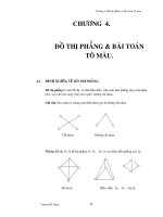
Figure 6.38 Successful transmission of a TPDU using the T = 1 transmission protocol. The XOR
option is used for the error detection code (EDC). A SELECT FILE command with a FID of
'3F00',
which selects the MF, is transmitted in the APDU. The incrementing of the send sequence count in the
PCB byte for each transaction, and the corresponding changes in the EDC, can be readily seen
used. The elaborate error correction mechanisms are a typical example. Although they may be
theoretically interesting, in many cases they are ineffective in dealing with actual transmission
errors. In practice, it is usually better to simply reinsert the card in the terminal and start a
new session, rather than using innumerable resynchronization requests to attempt to restabilize
communications. Consequently, the EMV specification imposes several restrictions relative to
the original ISO/IEC standard, as summarized in Table 6.40.
6.4.4 The T = 14 transmission protocol (Germany)
The ISO/IEC 7816-3 standard includes a tag in the ATR for designating a national transmis-
sion protocol. Such a transmission protocol is designated T = 14. With the introduction of
the C-Netz for mobile telephony and card phones in Germany, a protocol was needed for
communicating with the smart cards used in these systems. The character-oriented T = 0
protocol was considered undesirable, and at that time there was not yet a standardized block-
oriented protocol. Consequently, in 1987 Telekom decided to use a protocol developed by a
DIN working group. This protocol received the designation T = 14, which simply means that
it is a country-specific implementation. It had no significance outside of Germany, but it had
420 Smart Card Data Transmission
Table 6.40 Summary of the differences in the implementation of the T = 1 transmission protocol
between the ISO/IEC 7816-3 standard and the EMV specification
Mechanism or option ISO/IEC 7816-3 EMV
BWT expired Reset the card (for example) Deactivate the card
Smart card sends a request Allowed A maximum of three
to change the IFS successive requests is allowed
Smart card sends an S block Allowed Deactivate the card
with an abort request
Zero-length I block Allowed Prohibited
Terminal sends three Behavior according to Deactivate the card
successive blocks without specified error handling;
receiving a valid response usually a resync request
enormous influence on the development of the internationally standardized T = 1 protocol,
since the T = 14 protocol formed the principal foundation for this protocol.
The T = 14 protocol was used extremely widely in Germany, since it was employed in the
C-Netz mobile telecommunications network and public card phones. With the closing down of
the C-Netz at the end of 2000 and the change to the T = 1 protocol for public card phones, the
T = 14 protocol is no longer an important protocol in Germany, which is why it is described
here only briefly.
The T = 14 protocol has a block-oriented structure and works asynchronously using the
applied clock signal. The divider (clock rate conversion factor) has a value of 512, which yields
a data transmission rate of 9600 bit/s at a clock frequency of 4.9512 MHz. Data transmission
at layer 2 (the data link layer) always takes place using the direct convention. The size of the
buffers for transmitted and received blocks must be at least 50 bytes, with a maximum value
of 255 bytes. There is no block chaining mechanism.
6.4.5 The USB transmission protocol
A future amendment to the ISO/IEC 7816-3 standard will contain a specification for a new
transmission protocol for smart cards. This is the Universal Serial Bus (USB) protocol, which
has come to prevail over competing protocols, such as Firewire and the like, for use with smart
card applications.
The USB protocol requires a special hardware component in the smart card microcontroller,
but this component is already present in many chips, at least as an option. The major advantage
of USB with respectto currently used transmission protocols is that it is an established industrial
standard coming from the PC world. USB also offers a higher transmission rate than T = 0or
T = 1.
It presently appears that Version 1.1 of the USB specification will be used for smart cards,
with both the low-speed option (1.5 Mbit/s) and the full-speed option (12 Mbit/s) being sup-
ported, depending on the type of microcontroller. It should be noted that the effective trans-
mission rate is significantly lower than the stated values once the required protocol data have
been subtracted. USB Version 2.0, which has a data transmission rate of up to 480 Mbit/s (in
the high-speed mode), will not be used in the foreseeable future.
6.5 Message Structure: APDUs 421
Contacts C4 (AUX1) and C8 (AUX2), which up to now have been specified but not used,
will be used to implement the USB interface in smart cards. Further details will be specified
in the above-mentioned standard, but it can be expected that it will take several years until all
of the related standardization work is completed.
6.4.6 Comparison of asynchronous transmission protocols
With regard to comparing the various transmission protocols, a brief remark with regard to
achievable data transmission rates is in order. Attempts are often made to compare the T = 0 and
T = 1 protocols based on calculated effective transmission rates. However, such calculations
are only valid for specific commands in specific contexts. If they are generalized, they become
meaningless and invalid.
Both protocols have their strengths and weaknesses with regard to achievable transmission
rates. These are strongly dependent on very many individual factors, such as the transmission
error rate, the size of the I/O buffer in the card and the specific implementation of the protocol. In
short, it can be assumed that on average and with most applications, the effective transmission
rates of both protocols are nearly the same. If you want to increase the transmission rate,
changing the protocol will have little effect. It is more effective to reduce the divider value,
since this yields significantly better results.
Two international transmission protocols have been described in the previous sections. In
order to provide an overview, Table 6.41 summarizes the essential features of these protocols,
as well as their advantages and disadvantages.
Table 6.41 Comparison of internationally standardized asynchronous data transmission protocols
Criterion T = 0T= 1T= 2 (proposed)
Data transmission asynchronous, asynchronous, asynchronous,
half-duplex, half-duplex, full-duplex,
byte-oriented block-oriented block-oriented
Standard ISO/IEC 7816-3, ISO/IEC 7816-3, ISO/IEC 10536-4
GSM 11.11, EMV EMV
Divider freely definable, freely definable, freely definable,
usually 372 usually 372 usually 372
Block chaining not possible possible possible
Error detection parity bits parity bits, parity bits,
EDC at end of block EDC at end of block
Memory required ≈300 bytes ≈1100 bytes ≈1600 bytes
for implementation
6.5 MESSAGE STRUCTURE: APDUs
Applications protocol data units (APDUs) are used to exchange all data that passes between
the smart card and the terminal. The APDU is an internationally standardized data unit for the
application layer, which is layer 7 in the OSI model. In smart cards, this layer is located directly
422 Smart Card Data Transmission
above the transmission protocol layer. The protocol-dependent data units of the transmission
protocol layer are called ‘transmission protocol data units’ (TPDUs ).
A distinction is made between command APDUs (C-APDUs), which represent commands
to the card, and response APDUs (R-APDUs), which represent replies to these commands from
the card. In simple terms, an APDU is a sort of container that holds a complete command to
the card or a complete response from the card. APDUs are passed by the transmission protocol
transparently, which means without modification or interpretation.
APDUs that comply with the ISO/IEC 7816-4 standard are intended to be independent of
the transmission protocol. Consequently, the content and format of an APDU must not change
when a different transmission protocol is used. This applies above all to the two standard
protocols, T = 0 and T = 1. This demand for protocol independence affects the structure of the
APDUs, since it must be possible to transmit them transparently using both the byte-oriented
T = 0 protocol and the block-oriented T = 1 protocol.
6.5.1 Structure of the command APDU
A command APDU is composed of a header and a body. The body may have a variable length,
or it may be entirely absent if the associated data field is empty.
CLA INS P1
P2
Lc field Le fielddata field
header body
Figure 6.39 Structure of a command APDU
The header consists of four elements, which are the class byte (CLA), the instruction byte
(INS) and two parameter bytes (P1 and P2). The class byte is also used to identify applications
and their specific command sets. For instance, the class byte'A0' is used for GSM, while the
code '8X' is most commonly used for company-specific (private-use) commands. ISO-based
commands are coded by class byte '0X'. The standard additionally specifies the class bytes
to be used to indicate the use of secure messaging and logical channels. All of this is still
compatible with using the class byte as an application identifier.
The next byte in the command APDU is the instruction byte, which encodes the actual
command. Almost the entire address space of this byte can be exploited, with the sole restriction
that only even codes can be used. This is because the T = 0 protocol allows the programming
voltage to be activated by returning the instruction byte incremented by one in the procedure
byte. The instruction byte thus always has had an even value.
17
The two parameter bytes are primarily used to provide more information about the command
selected by the instruction byte.They thus serve mainly as switches that select various command
options. For example, they are used to choose various options for SELECT FILE or specify
the offset for READ BINARY.
17
See also Section 16.11.5, ‘The most important smart card commands’
6.5 Message Structure: APDUs 423
Table 6.42 The most important class byte (CLA) codes according to ISO/IEC 7816-4
b8–b5 b4 b3 b2 b1 Meaning
. . . . . . . . . X X Logical channel number
. . . 0 0 . . . . . . Secure messaging not used
. . . 0 1 . . . . . . Non-ISO secure messaging using a private method
. . . 1 0 . . . . . . ISO secure messaging, header not authentic
. . . 1 1 . . . . . . ISO secure messaging, header authentic
'0' . . . . . . . . . . Structure and coding compliant with ISO/IEC 7816-4/7/8
'8','9' . . . . . . . . . . . . Structure compliant with ISO/IEC 7816-4,
user-specific coding and meaning of commands
and responses (private use)
'A' . . . . . . . . . . . . Structure and codes compliant with ISO/IEC 7816-4,
specified in supplementary documents (e.g. GSM 11.11)
'F' 1111Reserved for PPS
Table 6.43 Summary of the assignment of class bytes to applications
Class Application
'0X' Standard commands compliant with ISO/IEC 7816-4/7/8
'80' Electronic purses compliant with EN 1546-3
'8X' Application-specific and company-specific commands (private use)
'8X' Credit cards with chips, compliant with EMV
'A0' GSM mobile telecommunication systems compliant with GSM 11.11
The section following the header is the body, which can be omitted except for a length
specification. The body serves a dual function. First, it specifies the length of the data section
sent to the card (in the Lc field)
18
and the length of the data section to be sent back from the card
(in the Le field).
19
Second, it contains the data for the commands that are sent to the card. If the
value of the Le field is'00', the terminal expects the card to return the maximum amount of data
available for the command. This is the only exception to the numerical description of the length.
The Le and Lc fields are usually one byte long, but they can be converted into fields that are
each three bytes long. Such fields can be used to represent lengths up to 65,536, since the first
byte contains the escape sequence'00'. The standard defines this three-byte length specification
for future applications. Due to the limitations of currently available memory sizes, it has not
yet been implemented.
The previously described parts of the command APDU can be combined to produce the
four general cases illustrated in Figure 6.41.
18
‘Lc’ stands for ‘length command’
19
‘Le’ stands for ‘length expected’
424 Smart Card Data Transmission
'00'
byte 1 byte 2 byte 3
Le/Lc (MSB) Le/Lc (LSB)
Figure 6.40 Structure of an extended Lc or Le field
header
header
header
header
case 1
case 2
case 3
case 4
Le field
Lc field
Lc field Le field
data field
data field
Figure 6.41 The four possible command APDU cases
6.5.2 Structure of the response APDU
The response APDU, which is sent by the card in reply to a command APDU, consists of an
optional body and a mandatory trailer, as shown in Figure 6.42. The body consists of the data
field, whose length is specified by the Le byte of the preceding command APDU. Regardless
of the value specified in the Le byte, the length of the data field can be zero if the smart card
terminates command processing due to an error or incorrect parameters. This is indicated in
the two single-byte status words SW1 and SW2 in the trailer.
SW1 SW2
data field
trailerbody
Figure 6.42 Structure of the response APDU
type 1
SW1 SW2
type 2
SW1 SW2data field
Figure 6.43 The two types of response APDUs
6.6 Securing Data Transmissions 425
The card must always send a trailer in response to a command. The two bytes SW1 and SW2,
which are also called the ‘return code’, encode the response to the command. For example, the
return code'9000' means that the command was executed completely and successfully. There
are more than 50 different codes. Their basic classification scheme is shown in Figure 6.44.
20
return code
(SW1 || SW2)
process completed process aborted
warning processing execution error checking errornormal processing
'61XX'
'9000'
'62XX' '63XX' '64XX' '65XX' '67XX' to
6FXX''
Figure 6.44 Return code classification scheme as defined by the ISO/IEC 7816-4 standard. The return
codes
'63XX'and'65XX' indicate that data in non-volatile memory (EEPROM) have been altered, while
the remaining
'6X' codes indicate that this has not occurred
If a '63XX' or '65XX' return code is received after a command has been executed, this
means that the card’s non-volatile memory (usually the EEPROM) has been modified. If
another code starting with '6X' is returned, command execution was terminated prematurely
without modifying the non-volatile memory.
It should be noted that although there is a standard for return codes, many applications use
non-standard codes. The only exception is the code'9000', which almost universally indicates
successful processing. With all other codes, it is always necessary to consult the relevant
specification in order to be sure of their meanings.
6.6 SECURING DATA TRANSMISSIONS
The entire data exchange between a terminal and a smart card uses digital electrical pulses on
the I/O line of the smart card. It is conceivable and not technically difficult to solder a wire
to the I/O contact, record all the communications for a session and later analyze them. In this
way, it is possible to gain knowledge of all the data transmitted in both directions.
A somewhat more difficult task is to electrically isolate the I/O contact, mount a dummy
contact on top of it, and then use thin wires to connect both of these contacts to a computer.
With this arrangement, it is easy to allow only certain commands to reach the card or insert
‘foreign’ commands into the communications sequence.
Both of these typical types of attack can succeed only if secret data passes unprotected over
the I/O line. Data transmission should thus basically be designed such that even if an attacker
20
See also Section 16.10.8, ‘Smart card return codes’
426 Smart Card Data Transmission
is able to eavesdrop on data transmissions and insert his own message blocks, he will not be
able to gain any advantage from doing so.
There are various mechanisms and methods that can be used to protect against these attacks
and against even more sophisticated types of attack. They are collectively referred to as ‘secure
messaging’. These mechanisms are not specific to smart cards, and they have been used for
a long time in data communications systems. What is special in the smart card domain is
that neither the processing capacity of the communicating parties nor the transmission rate is
particularly great. Consequently, commonly used standard methods have been scaled down
to match the capabilities of smart cards, without in any way reducing the security of these
methods.
The objective of secure messaging is to ensure the authenticity, and if necessary the con-
fidentiality, of part or all of the transmitted data. A variety of security mechanisms are used
to meet this objective. A security mechanism is defined as a function requiring the following
items: a cryptographic algorithm, a key, an argument and initial data as necessary. A general
condition must also be satisfied, which is that all security mechanisms must behave completely
transparently with regard to existing protocol layers, in order to ensure that existing, standard-
ized procedures are not adversely affected by secure messaging. This applies particularly to
the two transmission protocols T = 0 and T = 1, as well as to commonly used standard smart
card commands.
Before using a secure messaging method, both parties must agree on the cryptographic
algorithm to be used and a common secret key. According to Kerckhoff’s principle, the security
of the method relies entirely on this key. If it is revealed, secure messaging is reduced to a
generally known additional checksum that decreases the effective data transmission rate and
at best can be used to correct transmission errors.
Several different types of secure messaging methods have been known for many years. They
are all relatively rigid and tailored to specific applications. Most of them cannot be faulted as
far as security is concerned. However, none of them has become internationally predominant
or has proved to be sufficiently flexible to be included in current standards.
Security mechanism
key
cryptographic algorithm
initial data (optional)
argument
Figure 6.45 The data and functions required for a security mechanism
The requirements of transparency with respect to existing commands, use with two fun-
damentally different transmission protocols and maximum adaptability have led to the stan-
dardization of a very flexible (and correspondingly complex and elaborate) secure messaging
method in the ISO/IEC 7816-4 standard, with additional related functions defined in ISO/IEC
6.6 Securing Data Transmissions 427
7816–8.
21
This method is based on embedding all user data in TLV-coded data objects. Three
different types of data objects are defined:
r
data objects for plaintext: contains data in plaintext
(e.g., the data section of an APDU)
r
data objects for security mechanisms: contains the results of a security mechanism
(e.g., a MAC)
r
data objects for auxiliary functions: contains control data for secure messaging
(e.g., the padding method used)
The class byte indicates whether secure messaging is used for the command. The two
available bytes can encode whether the method specified in ISO/IEC 7816-4 is used and
whether the header is also included in the cryptographic checksum (CCS).
22
If the header is
included in the computation, it is authentic, as it cannot be changed during the transmission
without this being evident.
Data objects for plaintext
According to the standard, all data that are not BER-TLV coded must be encapsulated, which
means they must be embedded in data objects. Several different tags are used, as shown in
Table 6.44. Bit 1 of each tag indicates whether the data object is included in the computation
of the cryptographic checksum. If this bit is not set (e.g.,'B0'), the data object is not included
in the computation, while if it is set (e.g.,'B1'), the data object is included.
Table 6.44 Tags for plaintext data objects
Tag Meaning
'B0','B1' BER-TLV coded; contains data objects related to secure messaging
'B2','B3' BER-TLV coded; contains data objects not related to secure messaging
'80','81' No BER-TLV coded data
'99' State information for secure messaging
Data objects for security mechanisms
The data objects used for security mechanisms are divided into those used for authentication
and those used for confidentiality. The tags defined for this purpose are listed in Tables 6.45
and 6.46.
Here ‘authenticity’ refers to all data objects related to cryptographic checksums and digital
signatures. Data encryption, and marking such data as encrypted in the context of secure
21
Secure messaging is usually abbreviated to ‘SM’, which many programmers interpret as ‘sado-masochism’ on
account of the many degrees of freedom and room for interpretation provided by these two standards
22
For the coding of the class byte, see Section 6.5.1, ‘Structure of the Command APDU’
428 Smart Card Data Transmission
Table 6.45 Tags for authentication data objects
Tag Meaning
'8E' Cryptographic checksum
'9A','BA' Initial value for a digital signature
'9E' Digital signature
Table 6.46 Tags for confidential data objects
Tag Meaning
'82','83' Cryptogram; the plaintext is BER-TLV coded and includes data objects for secure
messaging
'84','85' Cryptogram; the plaintext is BER-TLV coded and does not include data objects
for secure messaging
'86','87' Indicates the padding method used:
'01' – padding with'80 00 . . .'
'
02' – no padding
messaging, fall under the heading of ‘confidentiality’. The tags listed shown in the above
tables must be used for secure messaging according to the type of method used.
Data objects for auxiliary functions
The data objects for auxiliary functions are used in secure messaging to coordinate the general
constraints. The two parties use these data objects to exchange information about the cryp-
tographic algorithms and keys used, initial data and similar basic information. In principle,
these items can be different for each transmitted APDU, or even between a command and
its response. In practice, though, auxiliary function data objects are rarely used, since all of
the general constraints for secure messaging are defined implicitly, so they do not have to be
specifically defined during communications.
Based on the options for secure messaging specified in ISO/IEC 7816-4, which have been
only briefly outlined above, we can describe two fundamental procedures. We have kept these
descriptions as simple as possible in order to make it easier to understand the complex mecha-
nisms involved. Due to the high degree of flexibility provided by the standard, there are many
other possible combinations of security mechanisms, some of which are even more complex.
The two procedures described here represent a compromise between simplicity and security.
The ‘authentic mode’ procedure uses a cryptographic checksum (CCS or MAC) to protect
the application data (APDU) against manipulation during transmission. The ‘combined mode’
procedure, by contrast, is used to completely encrypt the application data, so that an attacker
cannot draw any conclusions about the data content of the commands and responses that are
exchanged. A send sequence counter is only used with one of these two procedures. This
counter, whose initial value is a random number, is incremented for each command and each
6.6 Securing Data Transmissions 429
response. This allows both parties to determine whether a command or response has been
omitted or inserted. When a send sequence counter is used in combination with the ‘combined
mode’ procedure, identical APDUs appear to be different. This is called ‘diversity’.
6.6.1 The authentic mode procedure
The authentic mode procedure guarantees authentic transmission of APDUs, which means
that the APDUs are protected against manipulation during transmission. The recipient of an
APDU, which means a command or a response, can determine whether it has been altered
during transmission. This makes it impossible for an attacker to modify data within an APDU
without this being noticed by the recipient.
The fact that this procedure is being used is indicated by a bit in the class byte, so that the
recipient can act accordingly and check the received APDU for authenticity. The actual APDUs
are sent in plaintext and are not encrypted. The transmitted data are thus still public, and with
suitable manipulation of the transmission channel they could be intercepted and evaluated by
an attacker. This is not necessarily a disadvantage, since with respect to privacy legislation
it is better not to send confidential data via a public channel. In addition, the card user is at
least theoretically allowed the possibility of seeing what data are exchanged between his or
her smart card and the terminal.
In principle, any block encryption algorithm can be used to compute the cryptographic
checksum. For practical reasons, we assume that DES is used with a fixed 8-byte block length.
The individual data objects must therefore be ‘filled out’ to an integer multiple of eight bytes,
which is known as padding. In this process, data objects that are already an integer multiple of
eight bytes are nevertheless extended by one block. After padding, the cryptographic checksum
(CCS) of the entire APDU is computed using the DES algorithm in CBC mode. This 8-byte
checksum is appended directly to the APDU as a TLV-coded data object, with the four least
significant bytes omitted. All padding bytes are deleted after the checksum has been computed.
The modified APDU is then sent via the interface. This procedure extends the length of
the APDU by eight bytes, which only marginally reduces the transmission rate if normal
transmission block sizes are used.
The data objects for the control structures can also explicitly identify the algorithm and
padding method that are used. Here again we assume for the sake of simplicity that the smart
card and the terminal implicitly know all the parameters of the secure messaging system being
used.
When the protected APDU arrives at the recipient, the latter again pads it to an integer
multiple of eight bytes and then computes its own MAC for the APDU. By comparing the
MAC it has generated with the MAC generated by the sender, the recipient can determine
whether the APDU has been altered during the transmission.
A prerequisite for computing a cryptographic checksum is a secret DES key that is known to
both parties. If this key were not secret, an attacker would be able to break the authentic mode
communication procedure by intercepting an APDU, modifying it as desired and computing a
new ‘correct’ MAC. After this, he would only have to replace the original MAC with the new
one and send the newly created APDU on its way.
In order to better protect the keys used to generate the MAC against attacks based on known
plaintext–ciphertext pairs, dynamic keys are normally used. These are generated by encrypting
430 Smart Card Data Transmission
CLA'
CLA'
CLA
CLA' INS
INS
INS
INS
P1
P1
P1
P2
P2
P2
Lc
P1
P2
Lc
Lc'
Lc
data
data
data
data
CCS
CCS
PB PB
PBPB
T
DATA
T
DATA
T
DATA
T
CCS
L
DATA
L
DATA
L
DATA
L
CCS
key
(secret)
Step 1
Step 2
Step 3
Step 4
Figure 6.46 Generating a command APDU using the authentic mode procedure. This example uses
a case-3 command (e.g. UPDATE BINARY), with its header included in the cryptographic checksum
(CCS). A response APDU can be generated in a similar manner. ‘PB’ indicates the padding bytes
Step 1: The initial format of the APDU.
Step 2: The data section is converted into TLV-coded data, and the data
objects are padded to an integer multiple of eight bytes.
Step 3: The CCS is computed.
Step 4: A TLV-coded data object containing the CCS is added to the APDU.
a random number that has been previously exchanged between the terminal and the card. A
secret key known to both parties is used for this encryption.
The additional steps that are needed for the transmission and reception of an APDU that is
protected by the authentic mode procedure naturally reduce the effective data transmission rate.
On average, a good approximation is to assume that the rate will be half of that for unprotected
plaintext.
6.6.2 The combined mode procedure
Compared with the authentic mode procedure, the combined mode procedure represents the
next higher level of security. The data section of the APDU is no longer transmitted as plain-
text, but instead in an encrypted form. The procedure is an extension of the authentic mode
procedure.
In the combined mode procedure, as in the authentic mode procedure, the data objects to be
protected with a cryptographic checksum are first padded to an integer multiple of eight bytes
and then encrypted using the DES in CBC mode. The header is excluded from this process,
as required for compatibility with the T = 0 protocol. (If it is desired to encrypt the header
6.6 Securing Data Transmissions 431
as well, so that the command being sent the card is unrecognizable, the T = 0 ENVELOPE
command must be used.) One bit in the class byte indicates the use of secure messaging. The
data are transmitted across the interface after they have been encrypted. Since the recipient
knows the secret key that was used for encryption, it can decrypt the APDU. The recipient then
checks the correctness of decryption by recomputing the appended cryptographic checksum
in the same level of the transmission layer.
When this procedure is used, an attacker eavesdropping on the I/O line cannot discover
which data are exchanged between the card and the terminal in the command and response.
It is also not possible to replace one of the encrypted blocks within the APDU, since the
CLA'
CLA'
CLA'
CLA
CLA' INS
INS
INS
INS
INS
P1
P1
P1
P1
P2
P2
P2
P2
Lc
P1
P2
Lc
Lc
Lc'
Lc
DATA
DATA
DATA
DATA
DATA'
CCS
CCS
PB PB
PB
PBPB
PB
T
DATA
T
DATA
T
CCS
T
DATA
T'
DATA
L
DATA
L
DATA
L
CCS
L
DATA
L'
DATA
key
(secret)
key
(secret)
Step 1
Step 2
Step 3
Step 4
Step 5
Figure 6.47 Generating a command APDU using the combined mode procedure. This example uses
a Case 3 command (e.g. UPDATE BINARY), with its header included in the cryptographic checksum
(CCS). A response APDU is created in a similar manner. The padding bytes are indicated as ‘PB’.
Step 1: The initial format of the APDU.
Step 2: The data section is converted into TLV-coded data, and the data
objects are padded to an integer multiple of eight bytes.
Step 3: The CCS is computed.
Step 4: A TLV-coded data object containing the CCS is added to the APDU.
Step 5: The APDU data section is encrypted.
432 Smart Card Data Transmission
blocks are linked to each other by using the DES in CBC mode. Any replacement would be
immediately noticed by the recipient.
With regard to the cryptographic algorithm, the comments made in the description of the
authentic mode procedure apply here as well. In principle, any block encryption algorithm can
be used. The keys should be dynamic, as with the authentic mode procedure, which means that
session-specific derived key should be used for every session.
With regard to the security benefits, general usage of the combined mode procedure for all
APDUs can be recommended. However, increased security is accompanied by a considerable
reduction of the effective transmission rate. A good approximation for the difference in the
transmission rates for unprotected APDUs and those protected using the combined mode
procedure is a factor of four. The speed difference between the authentic mode and combined
mode procedures thus amounts to a factor of two. It is therefore necessary to carefully examine
each case, in order to determine which data should be transmitted in such a secure but time-
consuming fashion.
6.6.3 Send sequence counter
Using a send sequence counter mechanism for secure messaging does not by itself constitute
a security mechanism. It only makes sense to use a send sequence counter in combination
with the authentic mode or combined mode procedure, since otherwise any modification of
the count by an attacker would remain undetected.
The working principle of a send sequence counter is that each APDU contains a sequence
number that depends on when it is sent. This allows the deletion or insertion of an APDU in the
course of the procedure to be immediately noticed, so that appropriate measures (terminating
the communications) can be taken by the recipient.
This function is based on a counter that is initialized with a random number. This number
is sent to the terminal by the card at the start of the communications process, in response to a
request from the terminal. The counter is incremented each time an APDU is sent. The counter
should not be too short, but it should also not be too long, in order to avoid generating excessive
transmission overhead. The following description assumes the commonly used value of two
bytes, but longer counters may be used in practice.
There are two basic ways to incorporate a sequence count into command and response
APDUs. The counter value can be placed directly in the APDU as a numerical value in a data
object, or the counter value may be XOR-ed with a matching amount of data in the APDU,
following which a cryptographic checksum is computed and the modified data are restored
to the APDU. The recipient of this APDU knows the expected counter value, and can use
this value to modify the APDU in the same way as the sender. After this it can compute the
cryptographic checksum and check the correctness of the received APDU.
The following process takes place during communications. The terminal first requests an
initial counter value from the smart card. The smart card returns a two-byte random number to
the terminal. The terminal then sends the first secured command to the card, accompanied by
a send sequence count. Either the authentic mode or combined mode procedure can be used
to protect the counter and the body. The card receives the protected APDU and first checks
whether there is any sign of manipulation, based on the authentic mode or combined mode
6.6 Securing Data Transmissions 433
CLA
CLA
option 1
option 2
INS
INS
P1
P1
P2
P2
P3
P3
data
data
SSC
SSC
XOR
Figure 6.48 Two options for a send sequence count in a command APDU. In the first option, the send
sequence counter is a TLV-coded data object in the data section. In the second option, the send sequence
count is only coupled to the APDU data by an XOR operation used to compute the CCS
procedure. It then compares the counter value to the expected value. If these values match, no
APDU has been inserted or deleted during the transmission.
generate an
initial value x
for the SSC
communications
process using
the SSC
ASK RANDOM
APDU with SSC = x+4
random number as
initial value for the SSC
Smart Card
Terminal
APDU with SSC = x+3
APDU with SSC = x+2
APDU with SSC = x+1
Figure 6.49 Transmitting APDUs using a send sequence counter (SSC)
It is apparent that using a send sequence counter is attractive not only when several com-
mands have to be executed in a particular order, but also for individual commands, since each
session is made unique if a counter is used. Using a counter primarily provides protection
against ‘replaying’ previously sent APDUs and deleting APDUs.
If a send sequence counter is used together with the combined mode procedure, each
encrypted block is different, which creates a condition known as diversity. This is the result of
434 Smart Card Data Transmission
incrementing the counter for each APDU and the fact that with a good encryption algorithm,
changing a single bit in the plaintext affects the appearance of the entire ciphertext block.
6.7 LOGICAL CHANNELS
In smart cards containing several independent applications, it is optionally possible to address
these applications via logical channels. If logical channels are used, up to four applications
in a single card can concurrently exchange data with the terminal. The existing single serial
interface is still used, but the applications can be addressed individually at the logical level.
Two bits in the class byte (bit 1 and bit 2) are used to determine which command belongs
to which application.
23
This permits up to four logical channels,
24
so up to four sessions
with applications in the card can run in parallel. However, there is a limitation with regard
to communicating with the various applications in the smart card, which is that the external
processes that access the card must be mutually synchronized and are not allowed to interleave
their commands, since the response APDU from the card does not contain any information
about the logical channel of the originating command. This means that it is impossible to
externally determine which return code has been sent back in response to which command.
Due to the absence of channel identification, no new command can be sent until the response
to the previous command has been received.
The primary application for this very powerful mechanism is using several applications in
parallel. For example, suppose a cardholder is conducting a telephone conversation using the
GSM application in a multiapplication smart card. In order to confirm an appointment with the
other party, she needs to briefly consult her personal organizer, which is located in the same
card. Using a second logical channel, the terminal searches for a file in the personal organizer
application, in parallel with the GSM application, and then tells our highly stressed manager
whether she can agree to the proposed date. This is a typical use of logical channels. Another
conceivable example is securely transferring electronic funds between two electronic purses
in the same card.
The potential utility of logical channels for applications is matched by the difficulties that
their management entails for the smart card operating system. In principle, each logical channel
represents nothing less than a separate smart card, with all of its states and conditions. This
effectively means that the operating system must concurrently manage all the data for several
parallel sessions within its memory. The associated costs should not be underestimated, and in
particular this requires microcontrollers with large amounts of RAM. If secure messaging and
all possible types of authentication are also required for each logical channel, the amount of
memory needed very quickly rises to a level that can only be met by the highest-performance
types of currently available smart card microcontrollers.
23
See also Section 6.5.1, ‘Structure of the command APDU’
24
There is a proposal to revise and upgrade the ISO/IEC 7816-3 standard to increase the number of possible logical
channels to eight by using an additional RFU bit
7
Smart Card Commands
Communications procedures between a terminal and a smart card are always based on the
master–slave principle. This means that the terminal, acting as the master, sends a command
to the card, which as the slave immediately processes the command, generates a response and
returns its response to the terminal. The card thus never sends data without first having received
a corresponding command from the terminal. Even the ATR is no exception to this rule, since
it is a response to the reset signal, which is also a type of command to the card.
Actual communications always employ a transmission protocol, such as T = 0orT= 1.
These relatively uncomplicated protocols meet the special requirements of smart card applica-
tions and are optimized for this purpose. Deviations from these precisely specified protocols
within application procedures are not permitted. The transmission protocols allow data to be
sent to the card and received from the card in a manner that iscompletely transparent tothe trans-
port layer. The data are embedded in a sort of container called an application protocol data unit
(APDU). APDUs sent by the terminal to the card are the commands to the card. The terminal
also receives the responses to its commands in APDUs embedded in the transmission protocol.
There are a large number of commands based on this mechanism, and they initiate specific ac-
tivities within the card. The simplest examples are read and write commands for smart card files.
In smart card applications, the card is used as a data storage medium, an authorization
medium or both at the same time. This has led to the generation of command sets that are
optimized for these applications and transmission protocols and that are used only in the smart
card realm. Due to the severely limited memory capacity of smart cards, combined with market
pressure to allow only moderate increases in this capacity for cost reasons, command sets are
usually tailored to specific applications. All commands that arenot needed ina given application
are relentlessly removed during program optimization. Only a few operating systems exhibit
extensive command sets that have not been reduced to those needed for a particular application.
A diversification effect is also seen with smart card command sets, as is typical with new
technologies. Each company active in this area attempts to create its own commands that are
tailored to the needs of its operating system or anticipated application. This often arises from
necessity, since functionally equivalent commands may not exist in the standards. Companies
may also deliberately attempt to improve their positions relative to the competition, or to
deny their competitors access to a particular application area, by using commands that are
Smart Card Handbook, Third Edition. W. Rankl and W. Effing
C
2004 John Wiley & Sons, Ltd ISBN: 0-470-85668-8
436 Smart Card Commands
highly optimized with regard to card functions and memory usage. In any case, a decision
to use commands based on available standards always means choosing an open, more easily
expandable and proven system, which may later allow additional functions to be incorporated
into a single card. On the other hand, there are many examples of systems in which the use of
smart cards was only made possible by using highly optimized special commands.
There are currently 13 international standards and more or less stable draft versions of
standards that define typical smart card commands. They define considerably more than 100
commands, along with their associated procedures. To a large extent, the defined commands
are mutually compatible in terms of coding and functionality.
The majority of the commands currently used with smart cards are defined in the ISO/IEC
7816-4 standard, which is a general international standard. It is not dedicated to any particular
area, such as telecommunications or financial transactions, but instead attempts to address all
smart card applications. The commands in ISO/IEC 7816-4 are complemented by three sup-
plementary, specialized sections of this family of standards. ISO 7816-7 defines commands
for querying and managing smart card databases with structures based on structured query
language (SQL). ISO/IEC 7816-8 contains commands for executing and parameterizing cryp-
tographic functions, and Part 9 of the ISO/IEC 7816 family adds file management commands
to the basic command set.
There is no significant international standard in the area of financial transactions, but there
is an industry standard. This is the EMV specification, whose name comes from the initial
letters of Europay, MasterCard and Visa, the three initiators of this specification. Due to the
strong market position of the companies behind it, this specification has achieved the status of
a reference for all smart card operating systems, and it has the same degree of significance as
the ISO/IEC 7816 family of standards.
The GSM 11.11 specification, which was developed for use in the telecommunications
area, forms the normative basis for the SIM, while the TS 13.101, TS 31.111 and TS 102.222
standards specify the basic commands for the USIM. Due to the simple fact that a tremendous
number of smart cards are used in telecommunications applications, these standards represent
a de facto standard for commands for smart card operating systems.
In principle, special commands used only in a restricted area are not covered by these
standards and must therefore be specified individually. One example is the command set
specified for multisector electronic purse systems, which is defined in the CEN EN 1546
standard. This European standard defines all commands necessary for an electronic purse, along
with the associated procedures. A standard such as this, which is limited to a single application,
arises only in areas ofparticular interest togovernment agencies orspecific branches of industry,
due to the very high cost of generating such standards.
The commands in the standards and specifications described above can be classified ac-
cording to their functionalities. However, it must be remembered that only subsets of all these
commands are implemented in real-life smart card operating systems. Depending on the pro-
ducer of the operating system, more or less significant deviations from the functionality and
coding described in this chapter may be encountered. However, the basic functions described
here are in principle present in all operating systems. Of course, the functionality may be
severely restricted due to considerations of memory capacity or cost. Whenever a new applica-
tion is being planned, exact specifications of the coding and functions of all of the commands
must be requested from the producer(s) of the operating system(s) under consideration.
The following sections describe the most important and most widely used smart card com-
mands. The basis for this selection is formed by the following standards and specifications:
Smart Card Commands 437
Standards and specifications for smart card commands
general telecommunications
GSM 11.11
GSM 11.14
(SIM)
TS 31.102
TS 31.111
TS 102.222
(UICC, USIM)
ISO/IEC 7816-4
payment systems
EMV 2000
(credit & debit cards)
EN 1546
(electronic purses)
ISO/IEC 7816-7
(SCQL)
ISO/IEC 7816-8
(cryptographic functions)
ISO/IEC 7816-9
(file management)
CEPS
(electronic purses)
Open Platform
(application management)
Figure 7.1 The most important standards and specifications for smart card commands
ISO/IEC 7816-4/7/8/9, EMV 2000, GSM 11.11, TS 311.111, EN 726–3 and EN 1546–3. Ex-
tensive tables listing the coding of the most important smart card commands can be found in
Section 16.10.7, ‘Smart card command encoding’.
Naturally, it is impossible to buy a single smart card anywhere in the world that contains all
the commands described here. As a conservative estimate, the memory required for their full
implementation would be five to 10 times as large as the total amount of memory in the largest
currently available smart card microcontrollers. However, it is not at all necessary for a smart
card to be able to execute all of these commands. Depending on the intended application area
and operating system, certain classes of commands may be supported more comprehensively
than others.
For example, with a multiapplication card you would certainly want to make sure that
additional applications can be installed in the card after it has been personalized. A card for
cryptographic applications, assuming it has adequate memory capacity, will contain the full
spectrum of cryptographic commands, along with the various algorithms. Each application
area requires a different selection of commands from the various classes.
In each of the following descriptions, the standard or specification in which the command
is defined is identified in order to maintain an overview. If no source is given, the command
in question is used internally by smart card manufacturers and cannot be assigned to any of
the above-mentioned standards. Some of these commands are nonetheless very useful and will
probably be incorporated into a standard in the future.They thus are listed here with descriptions
of their basic functionality. In the interest of readability, we have omitted descriptions of the
coding of typical smart card commands in this chapter. This information can be found in
Section 16.10.7, ‘Smart card command encoding’.
Some commands are supported by nearly all smart card operating systems and have only a
limited number of options. For such commands, the command and response APDUs are fully
decoded in their descriptions. The internal processing sequences of seven typical commands
are also shown in psuedocode in Chapter 5 in the description of the ‘Small OS’ operating
system.
438 Smart Card Commands
For a given application, smart card commands can be classified into operational com-
mands, which are commands needed for normal use, and administrative commands, which are
commands needed for managing the smart cards and the application. For reasons related to
interoperability, operational commands are generally specified in complete detail in the stan-
dards. Administrative commands are often specific to particular operating systems and are not
necessarily specified by standards.
Command classes (part 1: card usage)
security
file operations
read
write
select
search
identification
authentication
cryptographic algorithms
numeric operations
database
application-specific
financial transactions
telecommunications
user management
database management
database query
health care
local public transport
Figure 7.2 Classification of smart card commands that are primarily used for operational functions
(while the card is in actual use)
For each command, the response shown in its description is the one received by the terminal
in the event of successful execution. Otherwise, if an operation is forbidden or an error occurs
in the card, the terminal receives only a 2-byte return code. Some of the described commands
also have parameters for selecting additional functions. These options often exist only in the
standard, rather than in actual operating systems, since they may be too complicated or have no
practical significance. Therefore, this chapter does not list or explain every option defined in the
standards, since our aim is to concentrate on practical functions. In describing the commands,
7.1 File Selection Commands 439
Command classes (part 2: others)
data transmission
production
operating system and
hardware tests
file management
unblock
block
create
delete
write data
completion
modify access conditions
test error-detection codes
write data patterns
test data patterns
Figure 7.3 Classification of smart card commands that are primarily used for administrative functions
(before and after the smart card is in actual use)
we have generally used the standard that has the largest number of functional options for the
command in question.
7.1 FILE SELECTION COMMANDS
Without exception, file management in all modern smart card operating systems is object-
oriented. Among other things, this means that before any action can be performed on an object
(which corresponds to a file), it must first be selected. Only then does the system know which
file is meant, and all subsequent file-specific commands apply to this file alone. Of course, the
access conditions for the file still must be checked within the operating system, in order to
determine whether the command in question is allowed or even possible.
The master file (MF) is always implicitly selected after the card has been reset, so it does not
have to be specifically selected. Other files are subsequently selected by executing the SELECT
FILE command. A file is addressed using its 2-byte file identifier (FID) or, in the case of a
directory file (DF), a 1-byte to 16-byte DF name. A DF name can contain an internationally
unique application identifier (AID) that is 5 to16 bytes long. It is possible to pass only a portion
of the AID, omitting the less significant bytes (those to the right). An additional parameter
causes the card to select the first, last, next or previous DF relative to the DF identified by the
abbreviated AID.
In connection with an older set of command definitions, the GSM 11.11 standard allows
only the 2-byte FID to be used for file selection. The ISO command set, by contrast, also
440 Smart Card Commands
supports a type of file selection using the path name of the file in question. The path name can
be either relative, in which case the file is selected starting from the currently selected DF, or
absolute, in which case the file is selected starting from the MF.
Only successful selection of a new file causes the previously selected file to be deselected.
If the selection cannot be completed, for instance because the requested file does not exist,
the previous selection remains in force. This ensures that a file is always selected, even in the
event of an error.
After successful file selection, the terminal may request information about the new current
file if necessary. This request, including the desired number of data items, is sent to the card
using the SELECT FILE command. The exact contents of these data items are defined in the
applicable standard. The data items returned by the card may include information about the
structure, size and amount of free memory of the newly selected file. The amount of data may
also depend on the file type.
Table 7.1 lists the explicit file selection options permitted by ISO/IEC 7816-4 for the
SELECT FILE command, and Figure 7.4 depicts the sequence of events in a typical file
selection process.
Table 7.1 The functionality of SELECT FILE according to ISO/IEC 7816-4
SELECT FILE
Command • FID (if EF, DF or MF)
or
DF name (if DF)
or
path to file from currently selected DF
or
path to file from MF
or
switch: select next higher-level DF
or
first, last, next, or previous DF (if a partial AID is transferred)
• switch: return information about the selected file
Response • information about the selected file (if selected via the switch)
• return code
In addition to explicit file selection using an FID, DF name or a path specification in a
SELECT FILE command, implicit file selection can be used. However, this is only possible
with standard read and write commands. A file can be selected before the command is actually
executed by specifying its 5-bit short FID as a supplementary parameter. However, in this case
the file must be an EF and it must be located within the current DF. The advantage of this
method lies in simplified command execution and increased processing speed, since it is not
necessary to send an explicit SELECT FILE command to the card.
1
1
See also Section 5.6.2, ‘File names’
7.1 File Selection Commands 441
Smart card Terminal
SELECT FILE
➔
Command [FID='3F 00';
no additional file information necessary]
Search for the file with FID =
'3F 00'
IF (file found)
THEN return code = OK
ELSE return code = file not found
Response [return code]
➔ IF (return code = OK)
THEN file selection successful
ELSE file could not be selected
Figure 7.4 Sample processing sequence for the SELECT FILE command
GSM 11.11 defines the STATUS command, which returns the same data to the terminal
as successful file selection using SELECT FILE. These data provide information about the
currently selected file: its type and structure, size, FID, access conditions and whether it is
blocked. This command is rarely used, and its main purpose is to allow the terminal to determine
which file is currently selected during a session and the currently valid access conditions.
Table 7.2 The functionality of STATUS according to GSM 11.11
STATUS
Command • —
Response • information about the currently selected file
• return code
EN 726–3 specifies the CLOSE APPLICATION command, which supplements SELECT
FILE and STATUS and is used to close applications. The FID of the application to be closed is
provided with the command, and the card responds by deleting the previously attained security
state. This command is mainly useful when a terminal needs to ensure resetting of the state
attained by the card. If the card’s operating system does not support such a command, this result
can only be achieved by a card reset. In the ISC/IEC 7816-4 definitions, selecting the MF is
sufficient to cause the security state of the previously selected file to be reset to its initial state.
Table 7.3 The functionality of CLOSE APPLICATION
according to EN 726-3
CLOSE APPLICATION
Command • FID (of the current DF)
Response • return code
442 Smart Card Commands
7.2 READ AND WRITE COMMANDS
Read and write commands primarily support using smart cards for secure data storage. These
commands can be used to write data to appropriate EFs and subsequently read these data. If
these EFs have specific access conditions, only authorized users are allowed to read them. The
data are thus stored in the card with protection against unauthorized access.
Since there are various types of EF data structures, there are also various types of read and
write commands for these files. Unfortunately, this does not fully correspond to an object-
oriented file management system. In a purely object-oriented system, the operating system
must be built such that an object can determine its own access mechanisms. This is not the case
for smart card file management. This non-compliance dates back to the historical emergence of
commands that were subsequently incorporated into current standards. The precursors of smart
cards, which are memory cards, have only one memory region that can be read and written
using offset and length parameters. Externally, this memory can be regarded as a single file with
a transparent structure. The first smart cards were built according to the same principle, and
the definitions of the commands for reading and writing transparent files date from this time.
Later, when other types of file structures were defined, new commands specifically adapted to
these structures were defined for use with such files. As a result, there are two different types
of file access.
Therefore this class of commands must be divided into commands for accessing EFs with
transparent structures and commands for accessing EFs with the other types of structures
(cyclic, linear fixed and linear variable). However, several standards (such as EN 1546 for
electronic purses) explicitly state that read commands for files with transparent structures may
also be used to read files with other types of structures. In any case, such commands can be
used to obtain additional data about the internal structure of the file.
An EF with a transparent logical structure is amorphous, which means that it does not
have any internal structure. It corresponds to a linearly addressable memory with byte access.
The READ BINARY command is used to read such a file, while the WRITE BINARY and
UPDATE BINARY commands are used for writing.
Table 7.4 The functionality of READ BINARY according to
ISO/IEC 7816-4
READ BINARY
Command • number of bytes to be read
• offset to the first byte to be read
• optional: short FID for implicit selection
Response • data read from the file
• return code
The fundamental difference between the WRITE BINARY and UPDATE BINARY com-
mands relates to the secure state of the card’s EEPROM. The secure EEPROM state is the
logical state of the EEPROM bits when the memory cells have taken on their minimum-energy
state. Since the memory cells are small capacitors, this means the state in which they contain