Visual Basic 2005 Design and Development - Chapter 4 pdf
Bạn đang xem bản rút gọn của tài liệu. Xem và tải ngay bản đầy đủ của tài liệu tại đây (954.11 KB, 28 trang )
Object-Oriented Design
This chapter discusses how to design the classes that make up the application. It explains the
major goals of object-oriented programming, and how they relate to the application’s classes.
This chapter also explains how you can use different views of the system to get a better under-
standing of the application as a whole. It introduces the Universal Modeling Language (UML),
which you can use to help specify and understand the application before you start building it, and
describes some UML design tools that you can use to model the application.
The Bug Hunter Example
The sections in this chapter explain different ways to characterize an application. They discuss the
program from the point of view of the users, architects, developers, and others.
To make the discussion easier, each section works with the same example: a hypothetical bug
tracking application named Bug Hunter. This application allows users to enter bug reports. A bug
manager reviews each report and assigns it to an appropriate developer. The developer reviews
the bug, tries to reproduce it, fixes the bug (hopefully), and clears the bug. A release coordinator
then performs regression testing, revises the application and user documentation, and then
releases a new version of the code.
In some cases, the bug can follow a different path, looping back to a previous state. For example,
if the assigned developer cannot reproduce the bug, it is sent back to the user for clarification. If
regression testing shows that the bug fix broke something, the bug is sent back to the developer for
reevaluation.
Throughout this process, users can view the status of a particular bug to see if it is new, under
review, assigned, under study, fixed, or released. The user can generate reports showing informa-
tion about bugs, selected and ordered in various ways, such as a particular bug, all bugs, bugs
08_053416 ch04.qxd 1/2/07 6:29 PM Page 69
with certain severity levels, bugs submitted during a particular time range, or bugs in various states
(new, assigned, fixed, and so forth).
The bug manager and release coordinator can also select reports that are not available to the users (such
as the code modules containing the bugs, the developers who wrote code containing bugs, and so forth).
Building an Object Model
Before you can start building an application, you must identify the classes that you will use. Once these
classes are defined, they will quickly become intertwined with the developers’ code. Changing, remov-
ing, or replacing them later becomes very difficult. You may be able to add new properties and methods
to a class. However, making large changes is time-consuming and likely to affect the existing code.
To avoid needless drudgery and frustration, you should spend extra time at the beginning of the project
identifying the major classes that you will use, spelling out their roles and responsibilities, and defining
(at least in general terms) their properties, methods, and events.
The following sections describe some methods you can use to pick classes for developers to use.
Picking Candidate Classes
One way of picking candidate classes is to take a close look at the project’s written specification or
description, and highlight all of the nouns in the text. For now, focus on nouns that are objects, such as
document, user, and report. Skip concepts and activities, such as testing and evaluation. The nouns you
have highlighted are the candidate classes.
The following text is the description of the Bug Hunter application with the candidate nouns in bold:
This application allows users to enter bug reports. A bug manager reviews each report and assigns
it to an appropriate developer. The developer reviews the bug, tries to reproduce it, fixes the bug
(hopefully), and clears the bug. A release coordinator then performs regression testing, revises the
application and user documentation, and then releases a new version of the code.
In some cases, the bug can follow a different path, looping back to a previous state. For example, if the
assigned developer cannot reproduce the bug, it is sent back to the user for clarification. If regression
testing shows that the bug fix broke something, the bug is sent back to the developer for reevaluation.
Throughout this process, users can view the status of a particular bug to see if it is new, under review,
assigned, under study, fixed, or released. The user can generate reports showing information about
bugs, selected and ordered in various ways, such as a particular bug, all bugs, bugs with certain
severity levels, bugs submitted during a particular time range, or bugs in various states (new,
assigned, fixed, and so forth).
The bug manager and release coordinator can also select reports that are not available to the users
(such as the code modules containing the bugs, the developers who wrote code containing bugs, and
so forth).
Next, combine any duplicates and make a list. Add comments, if necessary, to clarify a word’s meaning.
For example, the word “something” is too vague to be useful by itself. The following list shows the bold
nouns from the previous text:
70
Part I: Design
08_053416 ch04.qxd 1/2/07 6:29 PM Page 70
❑ all bugs (report)
❑ application
❑ bug
❑ bug manager
❑ bug report
❑ bugs in various states (report)
❑ bugs submitted during a particular time range (report)
❑ bugs with selected severity levels (report)
❑ code modules containing the bugs (report)
❑ developer
❑ new version of the code
❑ particular bug (report)
❑ path (a bug report’s path through the states/statuses)
❑ release coordinator
❑ something (a piece of code broken by a bug fix)
❑ state (of a bug report)
❑ status (of a bug report)
❑ the developers who wrote code containing bugs (report)
❑ user
❑ user documentation
Note that picking candidate classes in this way requires that you have a good specification. If the specifi-
cation is vague, it won’t include all of the nouns that you will need for the classes. The specification is the
starting point for building a list of candidate classes, not the final story. If something seems to be missing,
take another look at the specification and see if it completely describes what the program needs to do.
Converting Candidates into Classes
After you compile the initial candidate list, you must look over the items and decide which will make
good classes, and what interactions there are among them.
This list contains some items that represent the same concepts. The items “state” and “status” are really
the same concept, so you can remove one of them. Let’s remove “state.” Similarly, “bug” and “bug
report” represent the same idea, the data about a bug, so let’s remove “bug.”
Looking at the list, you can see a couple of general categories. There are several different kinds of reports.
There are also four kinds of people: user, bug manager, developer, and release coordinator. You should
pull these related objects out into groups. Such groups of objects often indicate a close relationship, and
may be a sign of inheritance, composition, or other close coupling.
71
Chapter 4: Object-Oriented Design
08_053416 ch04.qxd 1/2/07 6:29 PM Page 71
Think about the groups and decide whether these objects are the same type of thing at some level, or
whether they are just closely related. In this example, user, bug manager, developer, and release coordi-
nator are all the same sort of thing: people. It’s even easier to see that all of the reports are types of
reports.
Because the objects are the same sort of thing, it probably makes sense to combine them by making them
inherit from parent classes. Study these items further and see how much they have in common because
they are the same type of thing. The people items all have characteristics of people: name, address,
phone number, and so forth.
Different people will also have different permissions for using application features. For example, the bug
manager and release coordinator can make reports showing bugs by module or developer, whereas the
users cannot.
The report items are less well-defined at this point, so it’s a bit more difficult to know what they have in
common. Drawing on previous experience with other applications, however, you can guess that they
will all need methods for building the report, setting report parameters, saving the report into a file,
printing, exporting the report for analysis in a spreadsheet and possibly other file formats, and so forth.
Armed with this information, you can generalize the groups by pulling their common features into a
parent class, and making the items in the previous list child classes.
Now, consider the remaining items and think about the types of roles they will play in the application.
Decide whether the item represents a single piece of data, a more complex data structure with multiple
fields, something that performs an action (or on which important actions are performed), or a combina-
tion of these.
You can model a single piece of data by using normal variables such as strings, integers, or arrays of
similar simple data types.
You can implement a complex data structure in Visual Basic by using either a structure or a class. Both
structures and classes can provide methods, so you can use either to represent something that performs
actions.
The difference between a structure and a class in Visual Basic is mainly one of how the item is allocated.
A structure is allocated when it is declared, whereas a class is allocated when you use the
New keyword.
For example, if you declare an array of 1,000 structures, Visual Basic allocates memory for them when it
reaches the declaration. If you allocate 1,000 class objects, Visual Basic only allocates memory for refer-
ences to the objects, and doesn’t create the objects themselves until you initialize them individually by
using the
New statement. There are also a few additional differences (such as the fact that structures
don’t have constructors). I usually use classes, at least partly because they can have constructors.
The “bug report” item contains information about a bug, so it represents a piece of data. It is also a very
central concept to the system: a user creates it, the bug manager assigns it, a developer works it, and the
release coordinator releases it. It takes part in reports and requires user documentation. The fact that this
item plays a role in so many activities indicates that it is something special. Let’s make it a class.
In the earlier description of Bug Hunter, “application” refers to Bug Hunter in a fairly general way, and
it doesn’t really do anything specific. At most, you could use it to represent application properties such
72
Part I: Design
08_053416 ch04.qxd 1/2/07 6:29 PM Page 72
as the version number, release date, and so forth. Because this information changes rarely (only when
new versions are created) and because the “application” item doesn’t need to perform any action, let’s
tentatively remove it from the list. The program will store application information such as version num-
ber in the program’s properties and in the data describing a bug report.
I’ve seen many systems where object enthusiasts insist on creating objects for even small items such as
this. They would create an
ApplicationInformation class whose sole purpose is to load and save
these few data values. I prefer to initially keep these items simple and make them more elaborate later
only if it proves absolutely necessary.
Similarly “new version of the code” refers to a new program build to fix a bug. The new code itself is
stored outside of the program in some sort of source code control system. Though this is an important
part of the Bug Hunter system as a whole, it’s not properly part of the code.
The “user documentation” item also refers to something external to the program. Updating the docu-
mentation is an important activity, but it’s not part of Bug Hunter. Even if the program displays the
documentation online, it is the release coordinator, not the program, that updates the documentation.
You could add a property to the “bug report” object to record the version number of the documentation
produced in response to the bug, but even that may not be necessary. It’s more common for the docu-
mentation to include a revision history that will indicate that it was revised because of the bug.
The “path” item represents the path a bug report takes through the system as it is created, assigned,
worked, and released. Whether you need to keep this item depends on whether you really care about
the job’s path through the system or whether you just need to know that the job follows some path. In
some applications it is important to know an object’s complete history.
For example, if you are processing financial information, you may need to establish a chain of custody
so you know exactly who did what to the data and when. In that case, you might want to implement
an audit trail system where the application saves a record every time the data is modified (and possibly
viewed).
For Bug Hunter, let’s assume that you just want to know that a bug report flows through the system and
you don’t need to remember all of the steps, so let’s remove “path” from the list.
The “status” item represents a bug report’s current state in the system. This item takes specific values
such as
New, Assigned, and Released. The “status” item is a single enumerated value that applies to a
bug report, so let’s make it a property of the “bug report” object. In the Visual Basic code, let’s make the
list of possible values an enumerated type.
Finally, the “something (a piece of code broken by a bug fix)” item represents the code that was fixed.
This is another item that lies outside of Bug Hunter’s code. However, the program’s description says
that the bug manager should be able to generate reports showing bugs by module and bugs by devel-
oper. To provide those reports, the program must know where the bugs occurred and who created the
bugs. These are fairly simple data items, and the program won’t do anything with them other than
report them, so let’s make these properties of the “bug report” item. After fixing a bug, the developer
should enter this information in the “bug report” data.
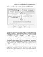
Figure 4-1 shows the initial object model.
73
Chapter 4: Object-Oriented Design
08_053416 ch04.qxd 1/2/07 6:29 PM Page 73
Figure 4-1: The initial object model contains objects extracted from the program’s description.
Adding Internal Classes
Sometimes an application’s object model needs additional classes that don’t correspond to the physical
objects mentioned in the project description. These classes provide features that the developers need to
build as parts of the system, but they are often hidden from the users.
Sometimes you may know that these classes are necessary from previous experience. In a similar appli-
cation, you may have used a
PriorityQueue class that you think will be useful for keeping bug reports
ordered by priority.
Other times you will discover that you need new classes as you develop the classes that you have already
defined. You may discover that the
Report object’s ExportToFile method would best be implemented
by a group of classes that can handle different export formats (such as tabbed text, comma-separated
value, Excel workbook, and others).
You may find additional classes when you apply design patterns to the application’s design. Model-
view-controller, facade, adapter, and other design patterns add new classes to the design.
It’s often useful to look at the places where the application interacts with the outside world to identify
new classes. That includes places that read or write files, such as the
ExportToFile method mentioned
earlier. It also includes places where the application must read or send email, upload or download files
from the Internet, print reports, send faxes, interact with Windows or other applications, and interact
with different components of your application.
BugReport
Status
FixedInVersion
BugInModule
BugWrittenBy
Description
ReportedBy
Etc.
Report
New()
Parameters
SaveToFile()
ExportToFile()
Print()
Etc.
Person
Name
Address
Phone
Privileges
Etc.
BugManager
Developer
ReleaseCoordinator
User
ReportBySeverity
ReportByModule
ReportByDeveloper
ReportSpecificBug
ReportAll
ReportByStatus
ReportByDate
74
Part I: Design
08_053416 ch04.qxd 1/2/07 6:29 PM Page 74
Adding Database Classes
A particularly common interaction is with a database. Many programs read and write data in a database,
and they can use classes to make that easier. Higher-level classes can act as factories for reading and
writing certain other kinds of objects. For example, a
DbPersonFactory class might have methods that
can build and save
Person objects in the database. A database-level class might provide methods for
inserting, updating, querying, and deleting data. Higher-level classes could use its methods instead of
accessing the database directly.
Separation between the day-to-day development classes and the database is important so that developers
don’t need to remember the details of the database’s structure and the particular database engine’s access
methods. For example, Access and Oracle databases delimit dates differently. The database classes
should hide this from higher-level classes.
However, I’ve worked on several applications where developers got carried away and added too many
extra layers of classes trying to increase the separation between the developers and the database. That
made tracing a piece of data through the system almost impossible. I’ve seen code that climbed through
30 or 35 layers of call stack involving dozens of objects to retrieve a relatively simple piece of data. This
is not only inefficient, but it’s also incredibly hard to debug.
Use classes for separation, but strive for broad, shallow object hierarchies, instead of very long inheritance
chains or deep stacks of method calls.
Often, the tables in a database map naturally to classes within the program. Perform a quick study of the
program’s data needs and design a preliminary database. Now see if any of the tables should correspond
to classes.
Tables that are related in the database often correspond to classes that are related in a similar way. Bug
Hunter will probably need a
BugReports table to store information about bugs and a People table to
store information about people.
There are two one-to-many relationships between the
BugReports table and the People table because
each
BugReports record will contain references to the User who created the report and the Developer
who is assigned to it. These are one-to-many relationships because each BugReports record refers to a
single creating user and assigned developer, while each user or developer can be associated with any
number of
BugReports records.
You will probably want to model this relationship by giving the
BugReport class references to the corre-
sponding
User and Developer objects.
Studying Different Design Views
It has been repeatedly shown that the longer it takes to find a bug in an application, the more difficult it
is to fix. Design decisions are particularly important, because you make them near the beginning of the
project and because they have such wide-ranging consequences. A big mistake in the initial design can
make the entire project fail.
One of the easiest ways to make big design mistakes is to not understand the application thoroughly. If
you don’t understand the customers’ needs, you can’t design classes to satisfy them. If you don’t under-
stand the application’s internal needs, you can’t design the classes that it needs to get the job done.
75
Chapter 4: Object-Oriented Design
08_053416 ch04.qxd 1/2/07 6:29 PM Page 75
To gain the best possible understanding of the system, you should look at the application from as many
points of view as possible. Some of the different views you should consider include the following:
❑ Object View —Perform an object-oriented analysis to define likely classes to represent the physi-
cal objects in the system. Group and combine objects, build an inheritance hierarchy, refine the
objects, and so forth.
❑ GUI View —Sketch out a rough user-interface design. Then think about the types of data the
program will need to support that interface. Often, the items displayed on the screen match
underlying classes. Chapter 5, “User-Interface Design,” has more to say about designing the
application’s user interface.
❑ Data View —Identify the data that the system needs. Decide where the data should reside: in
classes, global variables, or someplace else. Design the database if you need one and see if the
tables in the database naturally map to classes.
❑ Document View —In many applications, the users work on some sort of document. In Bug
Hunter, the central document is a bug report. Often these documents correspond to classes.
Mentally follow the documents through the system and identify the entities that interact with
them. In Bug Hunter, these are the different kinds of people and reports. Often, these entities
should also be implemented as classes.
❑ Case View —Step through the use cases that you and the users have defined for the application.
See if the classes you have defined contain all of the necessary ingredients to handle the use
cases. Look for new nouns in the use cases that might make good classes.
The Universal Modeling Language (UML), described later in this chapter, can help you characterize the
details of different aspects of the application’s design and behavior. It gives you a representation that
you and the other application designers can use to study the design meaningfully. Later, it can give
developers guidance so they share a common vision of how the system should work.
UML also gives you several new views from which to examine the system, so even if you are the sole
designer and developer on the project, you may get some benefit from using UML.
Improving the Classes
For years, object-oriented developers have focused on three important characteristics of object-oriented
languages: encapsulation, polymorphism, and inheritance. These three principles make classes more
powerful and easier to use with fewer chances for errors.
Unfortunately, many focus so tightly on those three principles that they forget the purpose behind the
dogma. By keeping in mind the reasons why those three concepts are useful, you can generalize them
and apply similar principles to higher-level design tasks. Most experienced developers understand that
a well-designed class should provide encapsulation, polymorphism, and inheritance. It’s less clear how
you can apply the underlying concepts to improve the design of higher-level entities such as application
systems and subsystems.
The following sections describe encapsulation, polymorphism, and inheritance. They also extract the
underlying ideas and explain how you can apply them to the application’s higher-level organization.
76
Part I: Design
08_053416 ch04.qxd 1/2/07 6:29 PM Page 76
Encapsulation
Encapsulation is the idea that a class should wrap up its implementation details in a tight little package.
The class provides an interface (properties, methods, and events) that lets other parts of the program
interact with the class’s objects, but it keeps the details about how it does its job a closely held secret.
Many programmers justify encapsulation by saying that it makes the rest of the program less dependent
on the class’s code. If you later need to change the way the class works, you will not need to modify the
rest of the program to work with the new code.
For example, suppose an
Invoice class looks up a customer’s data and the list of items that customer has
purchased, adds up the items’ prices, and prints an invoice. The main program can create an
Invoice
object and call its MakeInvoice method to make and print an invoice.
Now, suppose the company decides to create a new Preferred Customer program that gives any customer
a 10 percent across-the-board discount on every order after the customer has purchased $10,000 worth of
goods. You need to modify the
Invoice class so it checks the value of the customer’s previous orders. If
the customer has placed $10,000 worth of orders, the
Invoice class applies the 10 percent discount and
prints the invoice.
Because the
Invoice class encapsulates the invoice generation and printing process, you don’t need
to change the rest of the application. The main program still creates an
Invoice object and calls its
MakeInvoice method exactly as before. The details of how the MakeInvoice method works is safely
hidden from the main program.
You can also think of the ability to change one part of the application without messing up another part
as loose coupling. The different systems are related, but loosely enough that changes to one don’t neces-
sarily require changes to the others. Although developers think of encapsulation as a class-level concept,
loose coupling applies equally to all levels of the project. Keeping the user interface, report generation,
invoicing, inventory, and other major systems as loosely coupled as possible means changes to one are
less likely to require changes to the others.
A second part to encapsulation that is sometimes overlooked is the simple fact that it hides information
about the class’s internals. This is such an integral part of encapsulation that encapsulation is sometimes
called information hiding.
Even if hiding the class’s internals didn’t promote loose coupling, it would still have a large benefit for
developers because it allows them to use the class without worrying about what’s going on beneath the
surface, thus reducing the developer’s cognitive load. The developer can use the class and assume that
it works.
This may seem like the smaller of encapsulation’s two effects, but it can have a big impact, particularly
if you apply the idea to the higher levels of the application design. If the report generation system hides
its internal details from developers, those developers can work on their own pieces of code, calling the
report generation system as needed, without worrying about how it works.
On a large project where different teams implement the application’s various systems, keeping the sys-
tems as independent as possible is absolutely crucial. You must allow the teams to work separately to
get their pieces of the application done as quickly as possible. Information hiding allows members of
one system’s team do their jobs without needing to consult with the members of the other teams.
77
Chapter 4: Object-Oriented Design
08_053416 ch04.qxd 1/2/07 6:29 PM Page 77
One really strong way to promote loose coupling is to build parts of the application as dynamic link
libraries (DLLs), components, and controls. Most developers have the sense that classes in these kinds of
modules are separate entities. That makes them less likely to try to break the class’s encapsulation than
they might be if the class was simply another class in the same code base. Putting the class in a separate
code library adds a “barrier to messing around” with the code.
Of course, if it’s harder to modify the library’s code, then you’d better spend some extra time up front to
ensure that the library can handle all of the requests that the developers will need to make of it. The extra
work at the beginning will be more than repaid by the additional isolation you get between the applica-
tion’s systems.
To summarize, encapsulation really includes two concepts: loose coupling and information hiding. Both
of these are beneficial when you build a class, but they are also useful at the higher levels of application
design.
Hide as many of the details as possible within a class. Provide public access to the bare essentials that
other code needs to get the job done. If it later turns out that a piece of vital information that is hidden
within the class must be exposed, you can add it later. It’s better to start out too restrictive and loosen
access than it is to start too loose and create dependencies that will be hard to implement, debug, and
maintain.
Polymorphism and Inheritance
Encapsulation, polymorphism, and inheritance are the three main characteristics of object-oriented pro-
gramming. As the previous section explains, you can maximize encapsulation in your classes and system-
level design to make the application easier to build, debug, and maintain.
Polymorphism and inheritance, however, are more descriptions of objects, rather than advice on how to
use them.
Polymorphism means the ability to use one object as if it were another type of object. In particular, it means
that the code should be able to treat an object as if it had the type of its ancestor classes. You should be
able to treat a
User object as if it were a Person because User is a child class of Person. User is a type of
Person, so a User is actually also a Person. Note that the reverse is not true: a Person is not necessarily a
type of
User.
In practice, this means that you can pass a
User object into a routine that expects a Person. You can also
store a
User object in a variable that is a reference to a Person.
Inheritance means that derived classes inherit the properties, methods, and events of their parent classes.
A
User object has all of the features of a Person object, possibly with some additional features. The
User class may also modify some of the Person features (for example, overriding or shadowing them).
It’s hard to see how you would change a class’s definition to gain the most benefit from polymorphism
and inheritance, much less how to apply those principles at a higher design level. It helps to ask why
these capabilities are useful.
Both polymorphism and inheritance provide forms of code reuse. If a routine manipulates derived
classes as if they belonged to the parent class, you don’t need to write separate routines to handle each
derived class. If you write a routine to send email to a
Person object, you don’t need to write separate
routines to deal with
User, BugManager, Developer, and ReleaseCoordinator objects.
78
Part I: Design
08_053416 ch04.qxd 1/2/07 6:29 PM Page 78
Similarly, inheritance allows derived classes to reuse the code in their parent classes. If the Person class
defines
Name, Address, and Phone properties, you don’t need to define those properties in the User,
BugManager, Developer, and ReleaseCoordinator classes.
To take the greatest advantage of polymorphism, design and later program with the highest-level, most
abstract object types that you can. Suppose the application needs a piece of code that generates a report
listing bugs by date created and then prints the report. Rather than making the code work with a
ReportByDate object, write it to work with a variable from the parent class Report. Then you can reuse
the code to work with other kinds of reports. You may need to add some additional code to create the
different kinds of reports (or use a factory object to create the report without knowing what type it is),
but the rest of the routine should be the same for each report type.
To get the most out of inheritance, move functionality as high up the inheritance hierarchy as possible.
If the derived classes all have similar functionality, move the functionality into the parent class. Then the
benefits of inheritance follow automatically.
These ideas of looking for ways to make code more general sometimes contradict the agile philosophy of
implementing the simplest possible solution for the given situation without regard for code you will
need to write later.
For example, if you need to sort a list that could contain up to three integers, a simple series of
If Then
statements will suffice. There’s no need to waste extra time writing a powerful routine that uses the
bucketsort algorithm to sort huge numbers of values of arbitrary data types. That version will be harder
to write, debug, and maintain, and would provide no additional advantage over the simpler solution.
Though the keep-it-simple philosophy is important for agile development (and actually applies to non-
agile development, too), there’s no need to be intentionally stupid. If you see an opportunity to make the
code more flexible without a lot of extra effort, take it. This is particularly important during the early
stages of design where decisions will have far-reaching consequences.
When you write a subroutine or design a class, ask yourself if small changes would make it more general.
Can you make the routine work with more generic ancestor objects? Can you move common features into
a parent class? Both of these will promote code reuse.
UML
Universal Modeling Language (UML) is a design tool that developers can use to model a system’s behavior.
The idea is that a set of UML diagrams, use cases, and other depictions are to software engineers what
blueprints are to structural engineers and architects. Once you have a UML representation of an applica-
tion, you should be able to send that representation to all of the developers so that everyone has the same
view of how the system should behave. With this common vision, the developers can then start imple-
menting their separate pieces of the systems, confident that they are all working toward the same goal.
In addition to providing a consistent model of the application’s behavior for the developers, some projects
use UML to allow the users to help specify and understand the application. Unfortunately, UML is not
intuitively obvious. It takes some training and practice to use UML effectively. Few users have experience
with UML, and training them in its use can be difficult and time-consuming. Even after they understand
the ideas of UML, they may not have a good understanding of what the diagrams really mean. If you
have sophisticated users that either already understand UML or who pick it up quickly, you can use UML
79
Chapter 4: Object-Oriented Design
08_053416 ch04.qxd 1/2/07 6:29 PM Page 79
to help ensure that the design implemented by the developers matches the expectations of the users as
specified by the diagrams. If your users don’t have previous experience with UML, you might want to
focus only on the most intuitive diagrams: use case diagrams and activity diagrams.
In the projects I’ve worked on, we always tried to interact with the users in their own language. We
used simple tools that they use regularly and that are comfortable for them, such as word processing
applications, spreadsheets, email, telephones, and face-to-face conversations. We wanted them to focus
on their knowledge of the problem space and not get bogged down trying to learn UML or other devel-
opment tools. We wanted the users to concentrate on what they wanted to happen, and let the develop-
ers make software architecture decisions.
The following sections describe the most common types of diagrams defined by UML. The intent of
these sections is to give you an idea of what UML can do, not to be an exhaustive tutorial. They describe
only relatively simple versions of the diagrams. UML is a fairly complicated tool and includes many
detailed variations. To really learn UML, see a book about the subject such as Professional UML with
Visual Studio .NET by Andrew Filev et al. (Indianapolis: Wrox, 2002) or UML in Practice: The Art of
Modeling Software Systems Demonstrated thorough Worked Examples and Solutions by Pascal Roques
(Indianapolis: John Wiley & Sons, 2004).
Use Case Diagrams
A use case is a script for an action that the users will perform with the system. It describes the steps that a
user will follow to perform some specific task. When the application is finished, the users can run through
the use cases to verify that the application can handle them all.
The use cases for the bug reporting system describe how the users perform various actions. For example,
these would include the following:
❑ User enters a bug report.
❑ Bug manager reviews a bug and assigns it to a developer.
❑ Developer reproduces the bug, studies it, fixes it, and moves it into the “fixed” state.
❑ Developer fails to reproduce the bug and returns it to the user for more information.
❑ Developer reproduces the bug, studies it, discovers it should be better handled by another
developer, and returns it to the bug manager for reassignment.
❑ Release coordinator tests the fix and releases a new executable and user documentation.
❑ User generates a report giving a specific bug’s status.
❑ User generates a report listing all bugs with a specific state (for example, “open”).
❑ User generates a report listing all bugs with a specific priority (for example, “high”).
❑ Bug manager generates a report showing all bugs by code module.
❑ Bug manager generates a report showing total time spent clearing bugs in code by code module.
An application such as this one could easily have several dozen use cases. Depending on the number
and types of reports needed, it could have more than 100 use cases.
80
Part I: Design
08_053416 ch04.qxd 1/2/07 6:29 PM Page 80
I’ve worked on projects with a wide variety of use case needs. Some projects have only a couple of fairly
straightforward use cases. One of my most recent projects had only one use case, but it was extremely
complex, involving about two dozen steps and close to 1,000 data entry fields. Other projects I’ve
worked on had more than 100 use cases.
A project’s complexity and flexibility determines the number of use cases. In fact, the number of use
cases you and the users can come up with is a reasonable first measure of how complex an application
will be, although sometimes a fairly simple but powerful application can provide enough flexibility to
handle a large number of use cases.
Typically, a use case is a script that explains what each of the actors in the scenario need to do. It should
specify what needs to be done, but not how it should be done. The application’s design will determine
how the actors accomplish their tasks.
For example, the use case for entering a new bug report might look like the following:
The purpose of the UML use case diagrams is to help you visualize how the system’s actors interact with the
use cases. They also show how the use cases relate to each other by showing which actors perform the use
cases. For example, the “User enters a bug report” use case is related to the “User creates bug reports”
use cases because the same actor performs them: the user.
Use cases are drawn as ellipses. Actors are drawn as stick figures. Lines connect the actors to the use
cases that they perform.
To keep the use case diagrams simple, use cases are grouped into categories. Instead of listing every pos-
sible user report use case, the diagram contains a single object representing the “generate basic reports”
group of use cases.
The user enters data describing the bug including:
❑ Bug priority
❑ Date and time of bug
❑ Description of what the user was trying to do
❑ Description of actions the user took
❑ Description of what actually happened
❑ Error messages received
❑ Operating system and computer hardware
❑ Application version
The program should automatically display the user’s ID and include it in the bug
report.
After the user has entered the data, the application should save the bug report and
flag it so the bug manager can review and assign it.
81
Chapter 4: Object-Oriented Design
08_053416 ch04.qxd 1/2/07 6:29 PM Page 81
Figure 4-2 shows a use case diagram for the Bug Hunter application.
Figure 4-2: Use case diagrams show the relationships between actors and use cases.
The diagram also helps clarify who performs which actions for use cases that may not have been initially
spelled out in the requirements. In this example, the diagram shows that every actor can generate basic
reports (bugs by severity, bugs by status), but only the bug manager and release coordinator can gener-
ate advanced reports (bugs by module, bugs by developer).
From Figure 4-2, you can also see that some use cases are naturally grouped in a one-to-one mapping with
certain actors. For example, only the developer performs the “Fix bug,” “Return bug,” and “Reassign
bug” use cases, so you could group them into a larger category of “Developer cases.” Similarly you could
group the “Release fix” and “Reject fix” use cases into “Release coordinator cases.”
Use case diagrams can help the users understand the different roles the systems will define. This example
defines four roles: user, bug manager, developer, and release coordinator. The use case diagram shows
which activities these actors will perform. Often, you can use this as a basis for the application’s permis-
sion model.
User
Bug Manager
Developer
Release
Coordinator
Enter bug report
Assign bug
Fix bug
Return bug
Reassign bug
Release fix
Reject fix
Generate
basic reports
Generate
advanced reports
82
Part I: Design
08_053416 ch04.qxd 1/2/07 6:29 PM Page 82
Class Diagrams
Class diagrams show how the major entities in the system are related to each other. These form a static
view of the system showing relationships among objects in the system, and do not consider the system’s
dynamics (such as the flow of information or method call sequences).
Figure 4-3 shows the simplest diagram to represent a class. It is labeled at the top with the class’s name.
The next section lists the class’s properties. Below that are the class’s methods.
Figure 4-3: A simple class diagram shows
a class’s name, properties, and methods.
You can define much more complicated versions of the class diagram if you like to show details such as
property data types, method parameters and return types (for functions), and events. Some UML drawing
tools add icons to the left of the entries to indicate property or method. If you add every possible piece of
information, however, the class diagrams can become so cluttered that they are hard to use. Start with sim-
ple diagrams and add details only if you need them. Often, a very simple diagram such as the one shown in
Figure 4-3 is good enough to let you work on high-level design and study communications among classes.
A class diagram can show relationships among application domain objects. Those are the objects that the
users are familiar with, and include data objects such as the bug report, reports the user may generate,
and so forth.
You can use other class diagrams to study the classes that the program’s code will use. The objects in
that diagram might include queues, objects representing database tables, and so forth. Generally, these
diagrams are meaningful only to the developers, and not the users.
To indicate relationships among classes, you draw lines between them. Arrowheads and labels further
define the types of relationships.
To indicate that one class is inherited from another, use a hollow triangular arrowhead pointing to the
parent class. Figure 4-4 shows an inheritance diagram that indicates the
User, BugManager, Developer,
and
ReleaseCoordinator classes inherit from the Person class.
To indicate a non-inheritance relationship between two classes, use a solid line. If only one of the classes
is aware of the other, use an arrowhead to point to the class that is unaware of the other. You can add
labels to indicate the number of objects from each class in the relationship.
BugReport
ID
Status
Priority
ReportedBy
DateReported
DateObserved
DescriptionTryingToDo
DeveloperAssigned
:
AssignTo()
ReturnBug()
ReassignBug()
FlagAsFixed()
RejectFix()
:
83
Chapter 4: Object-Oriented Design
08_053416 ch04.qxd 1/2/07 6:29 PM Page 83
Figure 4-4: A class diagram can show an inheritance hierarchy.
In the relationship diagram shown in Figure 4-5, the
ReportSingleBug object represents a report about a
single bug. It is associated in a one-to-one relationship with the
BugReport object representing the
selected bug report. The
ReportSingleBug object knows about the BugReport, but the BugReport
object does not need to know about the ReportSingleBug, so the line connecting them has an arrow-
head pointing toward
BugReport. Each ReportSingleBug is associated with a single BugReport
object, so the right end of the relationship is labeled with a 1.
Figure 4-5: A class diagram can show relationships.
Each
BugReport object is related to the User who reported the bug and the Developer assigned to
the bug. Each
BugReport is associated with one User and Developer, but the Users and Developers
can be associated with any number of
BugReports, so the lines are labeled with a 1 by the User and
Developer and a * (meaning “any number”) by the BugReport.
Sometimes relationships are labeled to describe the relationship. The relationship diagram shown in
Figure 4-6 shows three relationships with the
BugReport class. Here User creates BugReports,
BugManager assigns BugReports, and Developer works BugReports.
Each of the diagrams shown in this section focuses on only a small part of the application. The goal is to
clarify part of the application’s behavior or design, not to model the entire application in a single mas-
sive diagram. It is frequently useful to make several diagrams that display different aspects of the sys-
tem such as an inheritance hierarchy, relationships, dependencies, and so forth. Often, it’s useful to focus
on the objects involved in a specific use case or transaction chain of events. For example, Figure 4-5
shows the objects that would be involved in printing a report about a specific bug.
These sorts of class diagrams don’t capture the step-by-step flow during a sequence of events, however.
For those, you can use sequence diagrams.
ReportSingleBug
BugReport
1
1*
1*
User
Developer
Person
DeveloperBugManagerUser
ReleaseCoordinator
84
Part I: Design
08_053416 ch04.qxd 1/2/07 6:29 PM Page 84
Figure 4-6: Labels can describe relationships.
Sequence Diagrams
Sequence diagrams use a timeline of events to describe a dynamic feature of the application. Across the
top of the diagram is a series of objects that will participate in the exchange. Below each object is a
dashed line called the object’s lifeline that indicates time progressing downward. A narrow rectangle
along the lifeline (called an activation) represents times when the object is performing some action.
As time moves on, objects send messages to each other to communicate and request actions. Usually, a
message in this context is simply a Visual Basic subroutine or function call. A sequence diagram repre-
sents messages as arrows from one object’s lifeline to another’s. Arrows for synchronous calls get solid
arrowheads and those for asynchronous calls get open arrowheads. Returns from messages (returns from
subroutine and function calls or raised events) are represented as backward-pointing dashed arrows.
Figure 4-7 shows a sequence diagram for a user generating a report of bugs with a particular status. The
names of the objects at the top are underlined to indicate that they are specific instances of classes, rather
than the classes themselves.
Figure 4-7: A sequence diagram shows a sequence of messages that
implement some action.
:User
:ReportedByStatus
New(status)
Print()
FetchRecords(query)
FormatReport(records : Collection)
records : Collection
report : ReportByStatus
:DataStore
BugReport
1
1
wor
ks
assigns
creates
*
*
User
BugManager
Developer
1
*
85
Chapter 4: Object-Oriented Design
08_053416 ch04.qxd 1/2/07 6:29 PM Page 85
The syntax for specific objects is the object’s name, followed by a colon, followed by the object’s class.
For example, the name
submitter:User means a User object named submitter. If you don’t need to
give a name to an object, you can omit the name as shown in Figure 4-7 to use unnamed objects.
The
User object creates a new ReportByStatus object. The diagram represents this by sending a New
message to the ReportByStatus object. The User passes a parameter named “status” in the New mes-
sage so the
ReportByStatus object knows what status to use when selecting bugs for the report.
Next the
ReportByStatus object sends a FetchRecords message to a DataStore object, passing it a
parameter named “query.” In this example, query might be a SQL statement that selects the desired bug
reports.
The
FetchRecord call to the DataStore object returns a value called “records” that has type Collection.
The
ReportByStatus object now sends itself a FormatReport message with a records collection as a
parameter.
After it has finished formatting the report, the original call to
New returns the new ReportByStatus
object. The User then calls the ReportByStatus object’s Print method asynchronously. At that point,
the
User object’s involvement ends and its activation stops. The ReportByStatus object handles the
Print request and then its activation stops as well.
Activity Diagrams
An activity diagram is a simplified representation of the steps that occur during an event sequence that is
less time-oriented than a sequence diagram. Figure 4-8 shows an activity diagram describing the tasks
shown in Figure 4-7.
Figure 4-8: An activity diagram shows a
sequence of events in an intuitive way.
Fetch records
Format report
Print report
86
Part I: Design
08_053416 ch04.qxd 1/2/07 6:29 PM Page 86
A dark circle represents the start of the activity that the diagram represents, and a dark circle with an
extra ring around it represents the end. This type of diagram is usually more intuitive than a sequence
diagram like the one in Figure 4-7, so it is more meaningful to users.
More-complicated activity diagrams can include
If-Then style branches, loops, and other more elaborate
structures. When you add all of the bells and whistles, an activity diagram looks a lot like an old-fashioned
flow chart.
Figure 4-9 shows an expanded and reformatted version of the activity diagram in Figure 4-8. This ver-
sion is called the swimlane version, because it shows the objects performing the actions in columns much
as lap swimmers move down the lanes in a swimming pool.
Figure 4-9: A swimlane activity diagram provides more detail about what object
performs each action.
In a sense, the swimlane diagram in Figure 4-9 is a combination of the activity diagram shown in
Figure 4-8 and the sequence diagram shown in Figure 4-7. It provides more detail than the activity dia-
gram, but is still intuitive enough that most users should be able to understand it. The sequence diagram
shows even more detail including method calls, return values, and asynchronous calls, but it’s intended
to help developers, and is usually too confusing for users.
State Chart Diagrams
A state chart diagram shows the states that an object is in over time. Figure 4-10 shows the state of a
BugReport object as it passes through the system.
Create ReportByStatus
Fetch records
Get records from
database
Print report
Format report
Send to printer
:ReportedByStatus :DataStore
:User
:User
87
Chapter 4: Object-Oriented Design
08_053416 ch04.qxd 1/2/07 6:29 PM Page 87
Figure 4-10: A state diagram shows an object’s states over time.
You can further break down some transitions to show sub-states. For example, you could break the
“developer fixes code” step into the sub-steps “study code,” “modify code,” “unit test,” “document
code,” “update manual,” and “flag as fixed.” You could then draw a state diagram for this sequence of
events, as shown in Figure 4-11.
Figure 4-11: You can break a state transition into sub-transitions and sub-states.
To aid tracking
BugReport objects through the system, the bug report data may actually include a
State or Status field to indicate its state in the system. This field would take the values New, Assigned,
Reproduced, Returned, Fixed, Tested, and Released. It might not need to include the sub-states Under
Study
, Code Modified, Unit Tested, Code Documented, and Manual Updated. Those are logical states
that the bug report passes through as the developer works on it. The developer might need to use different
tools while the report moves through these different states, so it may be important to include them in the
model of the system, but you probably don’t need to store them in the database.
Other objects might have states that are not ever explicitly recorded in the object’s fields. For example, a
Developer object has states corresponding to the BugReport states shown in Figure 4-11. Those states
study
code
modify
code
Reproduced
Developer fixes code
Under
Study
Unit
Tested
Code
Documented
unit
test
document
code
Manual
Updated
update
manual
Fixed
flag as
fixed
Code
Modified
New
User creates
bug report
Bug Manager
assigns
Developer
reproduces
Developer
fixes code
Return to
Developer
User adds
data
Assigned
Reproduced
Release
Coordinator
tests
Passes tests?
[No]
[Yes]
Reproducible?
[No]
[Yes]
Release
Coordinator
releases
Return
to user
User
cancels
Fixed
Returned
Tested
Released
88
Part I: Design
08_053416 ch04.qxd 1/2/07 6:29 PM Page 88
would be Studying Code, Modifying Code, Unit Testing, Documenting Code, and Updating
Manual
. A state diagram for the Developer object would include those states, although you may not
need to store the state in the
Developer class.
Component Diagrams
A component diagram shows interactions among the application’s self-contained, modular parts of the
system. These pieces of the application are often called systems, subsystems, or components. You can also
think of them as libraries or tools that support other parts of the application.
Components are drawn either as boxes with the text “<<component>>” at the top, or as boxes contain-
ing a box attached to two smaller boxes. UML 1.0 specifies a different notation with the box attached to
two smaller boxes containing the component. Figure 4-12 shows these three notations.
Figure 4-12: UML 2.0 allows the left and middle representations for a component,
whereas UML 1.0 specifies the representation on the right.
You can model dependencies between components with dashed arrows. If a component provides an
interface, you attach a small circle to the component with a line. If a component requires an interface,
you attach a semicircle to the component with a line. Together, an interface provided and required
makes a “ball and socket.”
Figure 4-13 shows a component diagram describing part of the Bug Hunter application’s report generation
code. The main Reporting Module is dependent on the Printer Services component, so a dashed arrow
points from Reporting Module to Printer Services. Reporting Module needs an interface to the Report
Generator and Report Generator provides the needed interface, so those components are connected with a
ball and socket link. Finally, the Report Generator needs an interface to the Data Store, and the Data Store
component provides the interface, so those components are also connected by a ball and socket link.
Figure 4-13: A component diagram represents dependencies and interfaces
among components.
<<component>>
Reporting
Module
<<component>>
Printer
Services
<<component>>
Report
Generator
<<component>>
Data
Store
<<component>>
Report
Generator
Report
Generator
Report
Generator
89
Chapter 4: Object-Oriented Design
08_053416 ch04.qxd 1/2/07 6:29 PM Page 89
Component diagrams represent interactions among high-level application design objects, so they are
purely for the benefit of the developers. They are usually meaningless to users, so there’s little point in
inflicting them on the users.
Deployment Diagrams
A deployment diagram shows the configuration of the physical hardware that will run the application.
Objects in the diagram are called nodes. UML 2.0 says that a device is a node that executes artifacts, where
an artifact is a piece of data that the system produces or uses, including executable files. Other types of
nodes include objects such as routers, modems, and printers that form part of the system but that don’t
hold artifacts. Lines between the nodes show their connections.
Figure 4-14 shows a deployment diagram for the Bug Hunter application. All of the application’s nodes
are connected to a router. The router also connects to the corporate LAN, so users of the application’s
computers can access the rest of the company’s online resources.
Figure 4-14: In this deployment diagram, nodes are connected by a simple network.
A Database Server computer stores the bug data in a SQL Server database. It also contains the Data Store
component responsible for managing the data.
<<artifact>>
Data
Store
<<artifact>>
SQL Server
Bug Database
Database Server
Router
Network
Printer
<<artifact>>
Bug Hunter
GUI
User
Computer
<<artifact>>
Bug Hunter
GUI
Bug Manager
Computer
<<artifact>>
Bug Hunter
GUI
Developer
Computer
<<artifact>>
Bug Hunter
GUI
Release Coordinator
Computer
Corporate
LAN
90
Part I: Design
08_053416 ch04.qxd 1/2/07 6:29 PM Page 90
The computers used by the users, bug manager, developers, and the release coordinator are all con-
nected to the router. Each of these computers runs the Bug Hunter’s graphical user interface.
Finally, the router is connected to a network printer, so all of the computers can print reports.
Because the deployment diagram deals with the system’s implementation, you might think it is for
developers only. Actually, users typically are very interested in the deployment configuration. They
either already own or must purchase the hardware that will run the application.
The users may need to restructure their environment to fit the deployment diagram. They may need to
move computers around, add routers, buy printers, re-cable buildings, and so forth. These sorts of
changes are usually very time-consuming, and the users might need to start planning months in
advance.
The users may also want to change the deployment diagram to represent a preferred scenario. For exam-
ple, they may want to move “heavier” artifacts onto new server machines so that the users can continue
using their existing computers with lighter loads. When you show the users the deployment diagram,
you may learn that they have remote users, so a local network won’t work. In that case, you may need to
adjust the diagram to allow for remote access over the Web.
Show the deployment diagram to the users early in the development cycle so that they can provide feed-
back before you make major architectural decisions.
UML Summary
UML defines diagramming functions that you can use to study an application’s behavior and design.
You can use it to make a large number of diagrams for modeling different aspects of the system. Not all
applications are the same, however, so some of the diagrams make little sense for some applications.
Use case diagrams help you understand which groups of users perform what actions. If you are building
a single-user application, this doesn’t make much sense. It would be a waste of time and energy to draw
a diagram with a single actor on the left connected to all of the use cases on the right.
Similarly, a sequence diagram is useful for studying calls between various objects as time passes. They
can be particularly helpful when several classes are involved, and when some of the calls are asyn-
chronous. They are not useful when one object synchronously calls a single method in another class.
I’ve seen several projects where developers believed (or were told) that it was necessary to provide
every possible UML diagram for reasons of completeness. Figure 4-15 shows a typical result. Sometimes
a picture is worth 1000 words. In this case, it’s only worth nine: “The User object calls the
BugReport
object’s Initialize method.” The diagram is correct, but hardly worth the effort.
If a UML diagram doesn’t make sense for your application, don’t bother to draw it. The goal is to specify
the system’s behavior and design precisely so that you can study it and develop a common understand-
ing with users, other designers, and developers. It’s not to create a bunch of diagrams with little to say.
91
Chapter 4: Object-Oriented Design
08_053416 ch04.qxd 1/2/07 6:29 PM Page 91
Figure 4-15: This UML diagram doesn’t say
anything that you can’t say in a few words.
UML Tools
You can draw UML diagrams on paper by hand, or with any drawing application. If you want extra sup-
port for UML-specific operations, you have plenty of tools to choose from.
The Objects by Design Web site has a table listing more than 100 UML tools at
ects
bydesign.com/tools/umltools_byCompany.html
. The tools range in price from free to more than
$11,000, work on a wide variety of platforms (including Windows, Linux, Unix, Java VM, and MacOS),
and are intended for use with an assortment of languages and development environments (such as Java,
Delphi, Smalltalk, Visual Studio, and Visual Basic).
Microsoft’s Visio Enterprise Architect product, which is available as part of Visual Studio 2005 Team
System or Visual Studio Professional with MSDN Premium, includes support for activity, collaboration,
component, deployment, sequence, statechart, static structure, and use case diagrams. It is also inte-
grated to an extent with Visual Studio.
To use Visio to “reverse-engineer” an application, load the application in Visual Studio. Open the Project
menu, open the Visio UML submenu, and select Reverse Engineer. Visio will open and gather informa-
tion about the application’s classes.
You can then use Visio to draw UML diagrams representing different aspects of the system. Figure 4-16
shows Visio editing a sequence diagram similar to the one shown in Figure 4-7.
To make a sequence diagram similar to the one shown in Figure 4-16, right-click the project in Model
Explorer in the lower-left part of the form. In the context menu, open the New submenu, and select
Sequence Diagram to create the new diagram.
From the UML Sequence tab in the toolbar (above the Model Explorer), drag three Object Lifeline tools
onto the diagram. Double-click an object to display the dialog shown in Figure 4-17. Enter the name you
want for the object, and use the Classifier drop-down list to select the object’s class. In this example, the
class is
SequenceDiagramTest (the project’s name) followed by User (the class).
:User
:BugReport
Initialize()
void
92
Part I: Design
08_053416 ch04.qxd 1/2/07 6:29 PM Page 92
Figure 4-16: You can use Visio to build UML diagrams such as this sequence diagram.
Figure 4-17: Use this dialog to set an object’s name and class.
93
Chapter 4: Object-Oriented Design
08_053416 ch04.qxd 1/2/07 6:29 PM Page 93