Aluminium Design and Construction - Chapter 4 pptx
Bạn đang xem bản rút gọn của tài liệu. Xem và tải ngay bản đầy đủ của tài liệu tại đây (462.3 KB, 28 trang )
CHAPTER 4
Aluminium alloys and their
properties
4.1 NUMBERING SYSTEM FOR WROUGHT ALLOYS
4.1.1 Basic system
The American system for designating wrought aluminium materials,
administered by the Aluminum Association (AA) in Washington, is by
now virtually standard worldwide [12]. For any given material, it employs
a two-part reference number, e.g. 3103–H14, 6082–T6 or 5083–0. The
four-figure number before the hyphen defines the alloy, and the symbols
after it the condition (or temper) in which that alloy is supplied.
Aluminium alloys can be either non-heat-treatable or heat-treatable.
The former are available in a range of work-hardened conditions, defined
by an H-number (as in the first example above), while the latter are
supplied in various conditions of heat treatment, specified in terms of
a T-number (second example).
4.1.2 Standardization of alloys
The four-figure number before the hyphen relates to a chemical
composition, i.e. an alloy. The AA supply a document (Registration Record
of International Alloy Designations) which lists the reference numbers of
all the alloys registered with them, together with their compositions.
The list runs to several hundred and is regularly updated. The new
European (EN) standards have adopted the same alloy numbers, but
prefixed by the letters AW (Aluminium Wrought). Thus, in the European
system, 6082 alloy is officially referred to as AW-6082, although in common
speech it is normal to omit the AW.
The following illustrates the way in which a composition is specified,
using the alloy 6082 as an example:
Si Mn Mg Fe Cu Cr Zn
0.7–1.3 0.4–1.0 0.6–1.2 0.5 0.1 0.25 0.2 %
Copyright 1999 by Taylor & Francis Group. All Rights Reserved.
Where a range is given, as for the first three elements, this denotes the
minimum and maximum permitted content of an intended ingredient.
Where a single figure is given (as for the last four) this refers to an
impurity, which must not exceed the value quoted. This is the official
way of specifying such an alloy. In everyday parlance, it is more convenient
to talk in terms of the nominal composition, quoting the mean percentages
of the intended elements only. The above 6082 alloy would be described
as containing a nominal:
Si 1.0 Mn 0.7 Mg 0.9%
Aluminium alloys are grouped into seven alloy series, depending on their
main alloying ingredient(s) (Table 4.1). The first digit of an alloy number
indicates the series to which that alloy belongs, while the other three usually
have no particular significance. An alloy series may be referred to collectively
by putting xxx after the first digit, i.e. the ‘5xxx series’.
Sometimes a slightly modified version of an existing alloy is registered,
in which case an ‘A’ may be added to distinguish it from the original
(e.g. 5154 and 5154A).
The AA also carry an 8xxx series, used for compositions that do not easily
fit into any of the first seven. One such type of alloy, containing a substantial
amount of lithium, has raised interest in the aircraft industry because of its
significantly lower density compared to other aluminium alloys.
4.1.3 Work hardening
Non-heat-treatable alloys are strengthened by means of cold work applied
during manufacture, as in the cold reduction of sheet or drawn tube.
The reduction per pass, and any heating, are controlled to produce the
required combination of strength and ductility. For a given degree of
cold work, the resulting increase in the proof stress (yield) is relatively
much greater than the increase in tensile strength (UTS), as compared
with the annealed condition.
The condition (or temper) of work-hardened sheet and drawn tube can
be crudely expressed in terms of its hardness, the standard tempers being
Table 4.1 The seven alloy series
Note. NHT=non-heat-treatable, HT=heat-treatable
Copyright 1999 by Taylor & Francis Group. All Rights Reserved.
quarter, half, three-quarter and fully-hard. The official system specifies
the temper by means of an H-number, such as H14, for example.
Table 4.2 lists the H-numbers in common use. The second digit after
the H is the important one, since this defines the actual hardness. Usually
this is an even number, the corresponding hardness being obtained by
dividing by 8 (e.g. H16=6÷8=3/4 hard). For special requirements, material
can be supplied to an intermediate level of hardness, in which case the
second digit is odd (e.g. H13).
The first digit after the H is of less direct interest, as it merely shows
the procedure used by the manufacturer to bring the material to its
final hardness. Possible procedures are:
• Temper-rolled (H1x). The material is cold reduced to the required
hardness, with no subsequent heating.
• Temper-annealed (H2x). The material is over-worked in the final pass,
and is then brought back to the required hardness by a partial anneal.
• Stabilized (H3x). The material is cold reduced to the right hardness,
and its properties are then stabilized by a relatively low temperature
application of heat. Such treatment may be necessary to prevent the
age-softening to which some work-hardened alloys are prone.
4.1.4 The O and F conditions
There are two other possible conditions in which material can be supplied,
defined as follows: O, annealed; F, ‘as-manufactured’. The O condition
defines material that has been fully annealed (i.e. softened) by heating.
The stronger F condition applies to products that are hot-formed to
their final shape, without any subsequent cold-work or heat-treatment.
It typically applies to hot rolled plate, or to sections in the as-extruded
condition.
The properties of F condition material cannot be controlled to the
degree that is possible with other conditions, and material specifications
only quote ‘typical’ strength values for such material, rather than
guaranteed minima. In the case of extrusions, the F condition strength
Table 4.2 Temper designations for non-heat-treatable material
Copyright 1999 by Taylor & Francis Group. All Rights Reserved.
will be only slightly above that for O. With plate, it is often considerably
higher, but not reliably so.
Often material ostensibly in the O condition gets very slightly cold
worked after annealing, as might occur in a straightening or flattening
operation. Such material is officially referred to as being in the H111,
rather than the O condition. However, the quoted properties are not
usually any different, and the use of the designation O for all such
material is unlikely to cause confusion.
4.1.5 Relation between temper and tensile strength
For work-hardened sheet material, there is a fairly consistent relation
between temper designation (H-number) and minimum tensile strength
(f
u
), as laid down in BSEN.515.
The fully-hard temper (H18, H28 or H38), referred to as Hx8, is
described as the ‘hardest temper normally produced’, and for any given
alloy it is defined in terms of a specific amount by which f
u
exceeds the
value f
uo
for the same alloy in the annealed (O) condition. The intermediate
tempers are then defined by taking equal steps in f
u
between the two
extreme conditions (O and Hx8). The resulting value for f
u
is effectively
given by the following expression (plotted in Figure 4.1):
f
u
=Pf
uo
+Q (4.1)
in which the coefficients P and Q are a function of the temper (Table 4.3).
This expression is based on the BSEN.515 rules and is valid for any
composition having an annealed tensile strength greater than about 90 N/
mm
2
(i.e. excluding pure aluminium). In practice the actual material standard
Figure 4.1 Relation between temper and minimum tensile strength (f
u
) for work-hardened
materials. f
uo
=minimum tensile strength in the O condition.
Copyright 1999 by Taylor & Francis Group. All Rights Reserved.
BSEN.485 for flat material lists values of f
u
that agree well, but not
precisely, with those predicted in the above manner.
For material of given hardness, the decision whether to use the H1x,
H2x or H3x condition is to some extent a matter of what the supplier
will provide. Only one of the three may be readily available (i.e. from
a stockist). Generally speaking, the H2x and H3x conditions have the
same tensile strength as the H1x, but with slightly lower proof stress
(f
o
) and higher elongation (el).
4.1.6 Availability of different tempers
In the new material standard (BSEN.485), non-heat-treatable alloys are
generally shown as being manufactured in the full range of possible
conditions. For each alloy (almost), strength data are provided for all
three types of temper (H1x, H2x and H3x), and also for the full range
of hardnesses in each type (Hx2, Hx4, Hx6, Hx8). But just because
every conceivable condition is covered in the standard, this does not
mean that they are all readily obtainable. For small orders, or with
material supplied by stockists, the availability will be much restricted.
The 1xxx and 3xxx-series materials are fairly readily available in the
temper-rolled conditions right up to fully-hard (H12 to H18). Some are
even offered as ‘super-hard’ sheet in an H19 temper, which is stronger
than H18 (but less ductile).
The temper availability of the 5xxx alloys is more restricted, because
the hardest tempers are difficult to produce and can only be offered in
large tonnages. The 5xxx-series sheet is normally produced to a maximum
hardness of Hx4 (or Hx2 in the case of the 5083 alloy), typically in a
temper-annealed condition (H2x). The harder tempers (Hx6, Hx8) have
attractive strength figures, comparable with those of 6xxx-series heat-
treated, but can only be considered if a large quantity is involved.
4.1.7 Heat-treated material
Wrought products in the heat-treatable alloys are strengthened by heat-
treatment after they have reached their final form. This comprises solution
treatment followed by ageing. The solution treatment consists of first
Table 4.3 Coefficients in equation (4.1)
Copyright 1999 by Taylor & Francis Group. All Rights Reserved.
heating the metal to a temperature of some 500°C, which causes the
alloying constituents to go into solid solution; and then quenching.
Immediately after the quench these constituents remain dissolved, but
with the passage of time they gradually precipitate out in the form of
small hard clusters, which impede the movement of dislocations under
stress, thereby raising the strength, a process known as age hardening.
Ideally, the solution treatment quench takes place in a tank from a
precisely controlled temperature, which depends on the alloy. However,
with the 6xxx series, the exact quenching temperature is less critical
and for extrusions in these alloys it is usually acceptable simply to
spray quench the metal as it comes out of the die, thus saving cost. With
some 6xxx extrusions, it is even possible to air quench with the spray
turned off, and still obtain useful properties.
After the solution treatment there are two options. Either the material
can be left to age naturally at room temperature over a period of days
(natural ageing), or it can be heated in an oven at a temperature of
about 150–180°C, this being known as artificial ageing or precipitation
treatment. The advantages of the latter are that the material ends up
stronger (but less ductile), and the final properties are achieved in
hours rather than days.
The condition (or temper) of heat-treated material is specified by
means of a T-number. Possible conditions range from T1 to T10, as
defined in BSEN.515. Three are of interest in structural design:
T4 solution treatment, followed by natural ageing;
T5 air quench, followed by artificial ageing (applicable only to some
6xxx-series extruded material);
T6 solution treatment, followed by artificial ageing.
T6 is the fully-heat-treated condition (maximum strength). T4 is more
ductile and is selected when formability is a factor. T5 may be chosen
for very thin extrusions, which would distort excessively if subjected to
a water quench.
Recent specifications distinguish between material that is not subjected
to a straightening process after quenching, and that which is. For plate
or sheet, the latter condition is indicated by adding the digits 51 to the
basic T4 or T6, while for extrusions and drawn tube the additional
digits are 510. In practice, this is a fairly academic distinction, since the
same properties are usually quoted for either condition. Therefore
designers will not go far wrong by simply writing T4 or T6.
4.2 CHARACTERISTICS OF THE DIFFERENT ALLOY TYPES
The general characteristics of the seven alloy series are summarized in
Table 4.4. Those most used in non-aeronautical construction are the
5xxx and 6xxx series.
Copyright 1999 by Taylor & Francis Group. All Rights Reserved.
4.2.1 Non-heat-treatable alloys
(a) 1xxx-series alloys
The materials in this series comprise commercially pure aluminium in
a range of purities. The third and fourth digits in the reference number
define the purity, by indicating the minimum percentage of aluminium
over and above 99.00. Thus ‘1050’ refers to a material having a purity
of at least 99.50%. Possible purities range from 99.00 to 99.99%.
Pure aluminium is weak, with a maximum possible tensile strength
of about 150 N/mm
2
. It is selected when corrosion resistance is critical,
as in chemical plant. The higher the purity the better the corrosion
resistance, but the lower the strength. In the O or F condition, pure
aluminium is relatively soft, and is used when high formability is needed.
The most ductile version is ‘super-purity’ (99.99% pure aluminium),
which is produced from lower purity metal by a further ‘zone-refining’
process.
(b) 3xxx-series alloys
The relatively low manganese content of these alloys, sometimes with
added magnesium, makes them half as strong again as pure aluminium,
while retaining a very high resistance to corrosion. Tensile strengths go
up to 200 N/mm
2
or more. In construction, the main application (in the
fully-hard temper) is for profiled sheeting, as used in the cladding of
buildings and other structures. 3xxx-series strip is also employed for
making welded tube (irrigation pipe, for example).
(c) 4xxx-series alloys
These Al-Si alloys are omitted from Table 4.4 because they seldom appear
in the form of actual members. Their usage is for castings (Section 4.5),
and weld filler wire (Section 4.6.2). At one time architectural extrusions
were occasionally produced in material of this type, because of the
attractive dark finish that can be produced on it by natural anodizing.
(d) 5xxx-series alloys
These represent the major structural use of the non-heat-treatable alloys.
The magnesium content varies from 1 to 5%, often with manganese
added, providing a range of different strengths and ductilities to suit
different applications. Corrosion resistance is usually excellent, although
it is possible for the stronger versions to suffer abnormal forms of corrosion
when operating in hot environments.
Copyright 1999 by Taylor & Francis Group. All Rights Reserved.
Table 4.4 Characteristics of different alloy series
Note. * The stronger alloys in the 5xxx series can have corrosion problems when operating for a long time in a hot environment.
Copyright 1999 by Taylor & Francis Group. All Rights Reserved.
The 5xxx alloys appear mostly as sheet or plate. At the lower end of
the range, they have good formability and are the natural choice for
sheet-metal fabrications. At the upper end, they are employed in welded
plate construction, typically in the F-condition. Such plate is tough and
ductile, with possible tensile strengths exceeding 300 N/mm
2
.
The 5xxx series is little used for extrusions, which are only available
in the O and F conditions with a rather low proof stress. Extrudability
is poor compared to 6xxx and very thin sections are impossible. Also,
the use of bridge-dies is ruled out, so that the only way to extrude a
hollow section is over a mandrel (Section 2.3.5). An acceptable practice
is to employ 5xxx-series plating with 6xxx extrusions as stiffeners.
4.2.2 Heat-treatable alloys
(a) 2xxx-series alloys
This comprises a range of alloys all containing copper, together with
other possible elements such as Mg, Mn and Si. Wilm’s original
‘duralumin’ was an alloy of this type (Section 1.4.4). The 2xxx-series
comprises high-strength products, and is largely confined to the aerospace
industry. Material for this market is mainly supplied to special Aerospace
Standards, with closer control of manufacture than that required by the
ordinary ‘general engineering’ ones, thus pushing up the cost.
In the naturally aged T4 condition, these alloys have mechanical properties
similar to mild steel, with a typical proof stress of 250 N/mm
2
, ultimate
tensile strength approaching 400 N/mm
2
and good ductility. In the full
strength T6 condition, the proof and ultimate stress can reach 375 and 450
N/mm
2
respectively, but with reduced ductility. The good mechanical
properties of the 2xxx-series alloys are offset by various adverse factors,
such as inferior corrosion resistance, poor extrudability, unsuitability for
arc welding, and higher cost. However, the corrosion resistance of thin
material can be improved by using it in the form of clad sheet (Section 2.2.5).
The American civil engineering structures of the 1930s were all in 2xxx-
type alloy, using the ductile T4 temper (Section 1.5.3). After 1945, the 2xxx
series was superseded by 6xxx for such use, despite the lower strength of
the 6xxx series. Today there is little non-aeronautical use of 2xxx alloys.
(b) 6xxx-series alloys
These materials, mainly containing Mg and Si, have the largest tonnage
use of the heat-treatable alloys. They combine reasonable strength with
good corrosion resistance and excellent extrudability. Adequate solution
treatment of extrusions can usually be obtained by spray quenching at
the die, and air quenching is possible with some of the alloys (Section
2.3.2). The 6xxx materials are readily welded, but with severe local
Copyright 1999 by Taylor & Francis Group. All Rights Reserved.
softening in the heat-affected zone. Broadly they divide into a stronger
type and a weaker type.
The stronger type of 6xxx material in the T6 condition is sometimes
described as the ‘mild steel’ of aluminium, because it is the natural
choice for stressed members. In fact it is a weaker material than mild
steel, with a similar proof or yield stress (250 N/mm
2
), but a much
lower tensile strength (300 N/mm
2
). It is also less ductile.
The weaker type of 6xxx alloy, which is not normally offered as sheet or
plate, is the extrusion alloy par excellence. It is more suitable than any other
alloy for the extrusion of thin difficult sections, and is a common choice for
members that operate at a relatively low stress level, especially when good
surface finish is important. Typical examples are when design is governed
by stiffness (rather than strength) as with many architectural members, or
when fatigue is critical, as for example in the structure of railcars.
(c) 7xxx-series alloys
These alloys mainly contain zinc and magnesium. Like the 6xxx-series,
they can be either of a stronger or a weaker type. The stronger type
embraces the strongest of all the aluminium alloys, with tensile strengths
in the T6 condition up to 550 N/mm
2
. The application of such alloys is
almost entirely in aircraft. They have inferior corrosion resistance, poor
extrudability and are unsuitable for arc welding. As with 2xxx alloys,
sheet can be supplied in clad form to prevent corrosion (Section 2.2.5).
The weaker type of 7xxx material is a very different proposition and
in the non-aeronautical field is a valid alternative to the stronger type
of 6xxx material, especially for welded construction. It has superior
mechanical properties to 6xxx material, and HAZ softening at welds is
less severe. But corrosion resistance, although much better than for the
stronger kind of 7xxx alloy, is not as good as with 6xxx alloy. Also there
can be a possibility of stress-corrosion. Extrudability is not quite as
good as for the 6xxx series, but hollow (bridge-die) extrusions are still
possible. An important factor, when using 7xxx-series alloy as against
6xxx alloy, is the need for greater expertise in fabrication.
4.3 DATA ON SELECTED WROUGHT ALLOYS
4.3.1 How mechanical properties are specified
Aluminium material standards quote two levels of stress, both of which
must be attained for a batch of material to be accepted:
f
o
minimum value of the 0.2% proof stress (or ‘0.2% offset’);
f
u
minimum tensile strength (or ‘ultimate stress’).
Copyright 1999 by Taylor & Francis Group. All Rights Reserved.
These are checked in mill tests, using coupons pulled in tension. The
testing machine in effect generates a stress-strain curve, and the proof
stress is determined by means of the well-known construction shown in
Figure 4.2. The tensile strength is taken as the fracture force divided by
the original section area of the coupon. Sometimes the standard fails to
give specified values and one has to make do with ‘typical’ ones, which
are not binding on the manufacturer.
The compressive proof stress is never recorded, and a designer would
normally assume it to be the same as in tension. This is often a reasonable
assumption, but may be incorrect for non-heat-treatable extrusions which
are hot-finished and then stretch-straightened. Because of the Bauschinger
effect, the tensile proof stress is likely to be enhanced and the compressive
proof depressed by so doing, the difference between the two values
being as much as 20% in some cases. This need not normally worry a
designer, because the f
o
-value quoted for such material tends to be
conservative.
Standards also call for a minimum percentage elongation el that any
batch must achieve. This is typically measured on a gauge-length of 50
mm and gives a crude indication of ductility.
4.3.2 Specific alloys and their properties
It is impossible in a book such as this to provide strength data for all the
aluminium materials that exist. Not only are there scores of registered
compositions in each alloy series, but their properties vary according to
form of product, temper and thickness. It is essential for a designer to refer
to an appropriate standard to find precise strength values for the materials
he/she is planning to use. Relevant standards, covering a total of some
Figure 4.2 Construction for obtaining 0.2% proof stress
o
from the stress-strain curve.
Copyright 1999 by Taylor & Francis Group. All Rights Reserved.
60 alloys, are:
BSEN.485 plate and sheet;
BSEN.755 extruded sections;
BSEN.754 drawn tube.
Figures 4.3 and 4.4 show compositions and minimum mechanical properties
for a representative range of aluminium materials, mainly based on the
above standards. Where a band is drawn, this shows the possible range
for the property concerned, depending on form and thickness.
Table 4.5 presents more specific data for a shortlist of alloys, covering
plate, sheet and extrusions. The strength of drawn tube can be estimated
by taking that for either equivalent work-hardened sheet material, or
else equivalent heat-treated extrusion material.
4.3.3 Comments on certain alloys
(a) 5xxx-series alloys
The A-rating for durability accorded to these alloys (Table 4.4) is usually
a true indication of their excellent corrosion resistance. However, when
such alloys have a magnesium content higher than about 3.5 or 4%, and
they are required to operate in a hot environment, there is a danger of
abnormal forms of corrosion (Section 4.7.1). For such applications, it is
desirable to keep the magnesium content down by using a weaker
alloy. For example, in the construction of welded tipper-truck bodies
one would normally select one of the strongest versions of 5xxx-series
alloy, such as 5083. But this alloy, with a nominal magnesium content
of 4.5%, becomes unacceptable if the body has to carry hot material. In
such a case, one should change to a weaker alloy with less magnesium.
The following 5xxx-series alloys, not covered in Table 4.5, also appear
in structural codes:
5052 (Mg 2.5, Cr 0.2) slightly stronger than 5251;
5754 (Mg 3.1) intermediate between 5251 and 5154A;
5454 (Mg 2.7, Mn 0.7, Cr 0.1) similar strength to 5154A.
(b) 6xxx-series alloys
As already explained, these alloys are broadly available in a stronger and
a weaker version. The latter with its superb extrudability is selected when
stiffness is the main criterion, the 6063 alloy being much used. For more
highly stressed situations, the stronger version becomes necessary,
popular alloys being 6082 in Britain, and 6061 in North America. The
6061 is not quite as strong as 6082, but is slightly better for forming. Other
Copyright 1999 by Taylor & Francis Group. All Rights Reserved.
Table 4.5 Minimum strength data for a shortlist of alloys
Note: MPa is the same as N/mm
2
Copyright 1999 by Taylor & Francis Group. All Rights Reserved.
Firure 4.3 Nominal composition and minimum properties (f
o
, f
u
) for a range of non-heat-treatable materials.
Copyright 1999 by Taylor & Francis Group. All Rights Reserved.
Figure 4.4 Nominal composition and minimum properties (f
o
, f
u
) for a range of non-heat-treatable materials.
Copyright 1999 by Taylor & Francis Group. All Rights Reserved.
popular alloys in the series are:
6060 (Mg 0.5, Si 0.4, Fe 0.2) slightly weaker than 6063, and even
more extrudable;
6005A (Mg 0.5, Si 0.7) a compromise alloy, lying between the
stronger and weaker kinds of 6xxx
material. Somewhat weaker than 6061.
(c) Weldable 7xxx-series alloys
The composition of the weldable (weaker) 7xxx-series alloys is adjusted
to obtain a compromise between strength and weld integrity. If such
material is over-alloyed, stress corrosion and cracking are likely to occur
at the welds. The alloy 7020 has been carefully designed to give good
strength with reasonable freedom from cracking, and an alloy such as
this would be the one normally recommended. The use of a stronger
version, in order to save weight, can only be considered if suitable
precautions are taken during fabrication, following specialist metallurgical
advice. The 7019 alloy, which probably represents the top end of the
practicable strength range for welded construction, has been successfully
used in large tonnages for military bridging.
4.3.4 Minimum bend radius
The bendability of flat aluminium material varies greatly from alloy to
alloy. The problem in fabrication is to know the minimum bend radius (r),
this being a function of the alloy, temper and metal thickness (t). Material
standards list minimum values of r/t, but these are only ‘recommended’
and not binding on the supplier. Here we present a rationalized procedure
for obtaining r/t, broadly based on the data given in BSEN.485. It must be
Figure 4.5 Approximate variation of minimum r/t with t for 90° bends in flat material.
Values of the bendability index a are listed in Table 4.6.
Copyright 1999 by Taylor & Francis Group. All Rights Reserved.
appreciated that in terms of practical fabrication the subject of bend
radii is not an exact science.
For any given thickness the minimum 90° bend radius may be
estimated with the aid of Figure 4.5, which gives curves of r/t plotted
against t. The appropriate curve depends on the bendability index of
the material being bent, values thereof being listed in Table 4.6 for a
range of alloys. The equation to the curves in the figure is:
(4.2)
where: A=0.3 -1.7; B=0.08 +0.5; and t=thickness in mm.
The curves in Figure 4.5 are valid for cold bending in thicknesses
from 1.5 to 10 mm. They apply to 90° bends. For bends beyond 90°, the
minimum radius will increase, especially in the harder tempers. With
work-hardened material, the bendability is slightly better for the H2x
and H3x tempers, than it is for H1x. For heat-treated material in the T4
temper, we have assumed that forming takes place after the material
has artificially aged to its final condition; a smaller r/t will be possible
if it is bent immediately after quenching.
The bending of extruded sections is an altogether more complicated subject,
and the reader is referred to the useful publication Aluminium Extrusions—
A Technical Design Guide, issued by the Shapemakers. (Section 1.6)
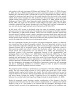
4.3.5 Strength variation with temperature
One weakness of aluminium as a structural metal is its fairly rapid fall-
off in strength with temperature. On the other hand, it has the advantage
that with decreasing temperature the properties steadily improve, and
there are none of the brittle fracture problems met with in steel. The
tensile strength of 6082-T6 goes down by 70% at 200°C, compared to
room temperature, but increases by 40% at–200°C.
Figure 4.6 shows how tensile strength varies with temperature (T)
for a range of alloys. The curves are plotted from data supplied by the
Aluminium Federation, based on specimens held for a long time at the
Table 4.6 Bendability index for flat material
Copyright 1999 by Taylor & Francis Group. All Rights Reserved.
relevant temperature and then tested at that temperature [1]. The reason
for the room-temperature values not agreeing exactly with those given
previously is that they were obtained from typical material, whereas
the Section 4.3.2 data were based on specification minima. Figure 4.7
gives more comprehensive data for two of the alloys [13], from which
we see that the loss of strength at temperatures over 100°C is considerably
more pronounced with 6082 than it is with 5083. Weakening with
temperature is a significant factor in the design of supersonic aircraft,
and special high-strength alloys have been developed to reduce the
effect. One such alloy is 2618, which under prolonged heating at 200°C
has twice the strength of 2014A (in the T6 temper).
Also of interest is the decrease in strength after a relatively short-
term exposure to elevated temperature (Figure 4.8). This is relevant to
the fire-rating of buildings and other structures.
4.3.6 Properties of forgings
Aluminium forgings range in size from small components, such as
the hinges, etc., on truck bodies, to the main members forming the
Figure 4.6 Variation of tensile stress (f
u
) with temperature. Tested at temperature T after
long-term exposure at that temperature.
Copyright 1999 by Taylor & Francis Group. All Rights Reserved.
Figure 4.7 Variation of proof stress (f
o
) and tensile strength (f
u
) with temperature, for two
alloys. Procedure as for Figure 4.6.
Figure 4.8 Variation of room-temperature properties after two-hour exposure to an elevated
temperature T for a typical batch of 6082-T6 material. f
o
=0.2% proof stress, f
u
=tensile
strength. (Alcan.)
Copyright 1999 by Taylor & Francis Group. All Rights Reserved.
undercarriages of aircraft. They are specialist products on which it is
essential to confer with the supplier.
Forgings are available in many of the usual wrought alloys. Non-
heat-treatable ones are supplied in the ‘as-manufactured’ F condition in
materials such as 5083, 5454 and 5251. The typical strength of these,
which will vary across the component, tends to be higher than the O
condition values for plate or extruded material. Heat-treated forgings
can be obtained in alloys such as 6082 and 2014, with properties in the
T4 and T6 conditions comparable to those for other wrought products
in those alloys.
4.4 STRESS-STRAIN CURVES
4.4.1 Empirical stress-strain relation
The shape of the stress-strain ( , e) curve is not mentioned in material
specifications, nor does it directly figure in design. But it is useful for
a designer to have a feel for it. Sometimes specialist computer programs
are employed, either for structural analysis or in research studies. Such
programs require the use of a suitable mathematical expression to relate
stress and strain, a convenient empirical relation being the well known
Ramberg-Osgood equation:
(4.3)
where E=modulus of elasticity, and
o
=actual 0.2% proof stress.
Figure 4.9 Ramberg-Osgood stress-strain equation (4.3), effect of n.
Copyright 1999 by Taylor & Francis Group. All Rights Reserved.
The two terms in this expression are respectively the elastic and plastic
strains. It will be seen (Figure 4.9) that the curve produced automatically
satisfies two necessary requirements, whatever the value of n:
1. There is (effectively) a linear elastic range.
2. The plastic strain correctly equals 0.002 when the stress reaches
o
.
The role of the index n is to control the curvature of the knee on the
curve. A high n produces a curve with a relatively abrupt knee, a low n
one with a more rounded knee. One can thus refer to ‘high-n’ and ‘low-
n’ materials. n typically ranges from 40 down to 5 for aluminium materials.
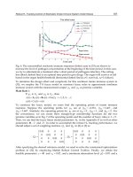
4.4.2 Stress-strain curve for minimum strength material
For any given alloy the actual properties of the material (as supplied)
will vary considerably from batch to batch, and also along the length
of an extrusion. For analytical purposes, it may be necessary to define
a stress-strain curve that would represent the response of minimum
strength material, i.e. material that just attains the specification values
for f
o
, f
u
and el. Referring to Figure 4.10, a curve is needed that goes
through the proof-stress point A and also the fracture point B. This is
achieved by putting
o
=f
o
in equation (4.3), and taking n as follows:
(4.4)
The curvature of the knee, defined by n, is strongly dependent on the
ultimate-proof ratio f
u
/f
o
but is insensitive to the elongation el. A material
with a low value of f
u
/f
o
will exhibit a relatively abrupt knee (high n),
whereas for material having a high f
u
/f
o
the knee will be more rounded
Figure 4.10 Construction for obtaining a stress-strain curve to represent minimum
strength material.
Copyright 1999 by Taylor & Francis Group. All Rights Reserved.
(low n). Much of aluminium construction is in materials that are either
fully heat-treated, or else in a heavily work-hardened condition. These
typically have a low ultimate/proof ratio (below 1.2) and hence a stress-
strain curve with a fairly abrupt knee. A higher value for f
u
/f
o
,
corresponding to a more rounded curve, would be exhibited by material
in the T4 or annealed condition.
Figure 4.11 gives curves constructed by the above method for a selection
of aluminium materials.
Mazzolani discusses the use of more precise mathematical expressions
for representing the stress-strain relation [26].
4.5 CASTING ALLOYS
Compared to forgings, castings are generally less ductile and weaker,
although tensile strengths up to 300 N/mm
2
are possible. They are cheaper
than forgings. The design of aluminium castings is beyond the scope of
this book, but below we give some limited data on certain alloys.
4.5.1 Numbering system
The unified system for specifying cast material, now adopted in Europe,
is described in BSEN.1706. For a given material it uses a two-part reference,
such as AC.51400-F or AC.42000-T6, in which the first part refers to the
alloy, and the second part to the condition. In Britain, the new European
alloy numbers for castings supersede the old ‘LM’ system, although the
actual compositions are broadly the same.
Figure 4.11 Minimum stress-strain curves for a selection of aluminium materials, based on
a thickness of 6 mm, generally for flat material. The 6063 curve is for 6 mm thick extruded
profile.
Copyright 1999 by Taylor & Francis Group. All Rights Reserved.
The first digit in the number indicates the alloy series, which depends
on the main alloying ingredients in the same way as for wrought alloys
(Table 4.1). Thus the AC.4xxxx series covers alloys containing just Si, and
the AC.5xxxx those with substantial Mg. Unlike wrought, the European
numbers for casting alloys do not tally with the American ones.
The symbol or symbols after the hyphen have the same basic meanings
as for wrought material:
F ‘as-manufactured’, i.e. as cast;
T4 solution treated after casting and naturally aged;
T6 solution treated and artificially aged.
4.5.2 Three useful casting alloys
A wide range of casting alloys exists, generally different from those used
for wrought products. Table 4.7 provides data for three selected alloys,
which should form part of a designer’s repertoire. The values quoted in
the table are minimum strengths to be achieved by separately cast tensile
specimens. They do not accurately represent the metal in the actual casting,
the properties of which are unlikely to be uniform. Alternative strength
values are given, depending on whether a sand mould is used or a
permanent one (chill cast), the chill-cast strength being always higher.
AC.44100
This is a non-heat-treatable alloy, available in the as-cast F condition. It
is the most popular casting alloy in aluminium, because of its exceptional
fluidity. It is suitable for intricate shapes and can cope with thicknesses
down to about 2.5 mm. At the other end of the scale, it can be used for
very large castings, up to 3000 kg in sand and 200 kg in permanent
mould. It has good corrosion resistance and is successfully employed in
‘on-deck’ marine applications.
Table 4.7 Three selected casting alloys
Copyright 1999 by Taylor & Francis Group. All Rights Reserved.
AC.51400
This is another non-heat-treatable alloy. It finds application instead of
AC.44100 when appearance is critical, because of its exceptional corrosion
resistance and suitability for anodizing. But, against this, it has inferior
fluidity, ruling out its use for thin intricate castings. Good foundry
practice is important.
AC.42000
This heat-treatable alloy, in the T6 condition, is chosen when higher
strength is needed. Like AC.44100, it has excellent fluidity and good
corrosion resistance. Also it is more readily machined.
4.6 ALLOYS USED IN JOINTS
4.6.1 Fastener materials
Chapter 11 includes design data on four typical alloys for use as fasteners,
namely 6082, 6061, 5154A and 5056A. The first three have already been
mentioned above (Section 4.3). The fourth is an alloy containing a nominal
Mg 5.0 and Mn 0.35% that produces fasteners as strong as 6082. Because
of its high magnesium content it is unsuitable for prolonged use in hot
environments.
Stronger alloys are employed for the fasteners used in aeronautical
construction. These can be in 2xxx-series alloy (T4 or T6 temper), or in
a strong 7xxx-series material such as 7075-T6. In the USA strong fasteners
in these materials also find use outside the aero field.
4.6.2 Weld filler wire
Alloys for use as welding wire are divided into four types (Section
3.3.4). Table 4.8 lists, with their nominal compositions, the alloys of
each type that are covered in BS.8118.
4.7 CORROSION
4.7.1 Corrosion of exposed surfaces
Any aluminium surface exposed to air develops a thin oxide film, which
is hard, chemically stable and tightly keyed to the metal. Though very
thin (typical thickness 0.005 mm), this layer prevents further oxidation.
When damaged, it immediately reforms, provided oxygen is available,
and it is this that gives aluminium its good durability.
Copyright 1999 by Taylor & Francis Group. All Rights Reserved.
Atmospheric corrosion of aluminium is by a process of pitting. Often
referred to as ‘weathering’, this is radically different from the rusting
of steel. Air-borne pollutants, such as sulphuric acid and sodium chloride,
cause local pits to form, the depth of which may be used as a measure
of the severity of the attack. In the first year, the pit depth increases
relatively quickly, but with the passage of time the corrosion products
effectively stifle the process. Eventually, after five years or so, further
corrosion almost stops. This pattern of behaviour is illustrated in Figure
4.12, which shows the likely variation of average pit depth with time for
3103 sheet in an outdoor industrial location [32].
The severity of pitting depends on the alloy and the environment. For
a very durable alloy, such as 3103, the worst pits may have a depth after
five years of roughly 0.04 mm in a rural location, 0.08 mm in an inland
industrial one and something like 0.16 mm at an industrial site by the sea.
The surface of weathered aluminium always looks much worse than
it really is, and the immense volume of the corrosion products (some 200
Table 4.8 Nominal composition of weld filler alloys
Note. * The use of these fillers may lead to corrosion problems under prolonged exposure in a hot
environment
Figure 4.12 Pitting corrosion. Typical growth of average pit depth with time for exposed
3103 sheet in an inland industrial location (Alcan.)
Copyright 1999 by Taylor & Francis Group. All Rights Reserved.