Hints on the use of Pro-Engineer for Sheet Metal Design docx
Bạn đang xem bản rút gọn của tài liệu. Xem và tải ngay bản đầy đủ của tài liệu tại đây (2.39 MB, 26 trang )
1B Integrated Design Project
Hints on the use of Pro-Engineer
for Sheet Metal Design
(based on ProE version “Wildfire 2”)
1 Philosophy
As was demonstrated in the final CAD sessions of part 1A, Pro-engineer has an
application dedicated to sheet metal components, with the ability to flip between the folded
component and the flat pattern (usually referred to as the development) as cut out prior to
bending. Most modern cutting machines, whether using punches, laser beams or water jets,
can accept DXF files, as produced by many CAD packages, as the main instruction input,
thus making savings of time and effort while decreasing opportunities for error.
The following notes are a guide to the use of Pro-engineer in the IDP. Whilst
modelling your design does require some investment of time, it will more than repay this
when cutting out and modifying your chassis and other components as well as providing the
power to check for interferences and to animate mechanisms.
As designers, it is important to remember that the primary purpose of producing a
drawing or a model is to provide a statement of your requirement. Whilst a good designer
will design for a method of manufacture, the role of a drawing as a set of manufacturing
instructions is secondary, in that manufacturing processes evolve and skilled technicians will
have their own techniques. When modelling a folded sheet metal component, your
requirement is for the fully folded item and so this is what should be modelled. The power of
ProE can then be employed to derive the flat development for cutting out and subsequent
bending.
Example - Production of a simple bracket.
Launch ProE in the normal way, start a new model and immediately change the
APPLICATION to Sheetmetal. (Confirm this and the icons on the right hand edge of the
model window will change.) Until a first wall is present the only icon highlighted as
available is the 4
th
from top. This has a fly-out menu which includes the options: “Create
Unattached Flat Wall” and “Create Unattached Extruded Wall”. The first allows the
modelling of a flat panel, of any shape, which may be subsequently bent up. This would,
however, be contrary to the stated principle of “draw the requirement” as it would not afford
control of the final dimensions of the folded component. Any changes to the material
thickness or bend allowance would cause variations to overall dimensions.
Using the option of “Create Unattached Extruded Wall” allows the bent component to
be drawn and final, overall dimensions to be fixed. Select this icon and accept defaults and
select a sketching plane. Remember that it is the edge view of the component being drawn,
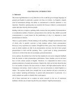
complete with bends of suitable radii. The following diagram shows the sketch of a “Z”
bracket.
S.P.Tebboth September 2004
Note that the sketch consists of a single line which is “Thickened” via the RMB
MENU. Direction of thickening and material thickness are selected, whilst bend radii have
previously been chosen to be internal or external depending on thickening direction.
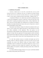
Note that after thickening, dimensions can be re-defined to include material thickness, as in
the example below, where overall length is now controlled as well as the internal bend radii
made equal.
The sketch can now be accepted by clicking on the tick icon and with a blind extrusion
depth specified the folded bracket produced as shown below.
. 2
2 Starting the Chassis
Whilst complex parts can be built up by creating an unattached wall and subsequently
attaching extra features to it, it is usually quicker and simpler to start off with a solid
extrusion when designing something like a chassis with multiple bends.
The recommended procedure is described below, using an example to illustrate the various
stages.
2.1 Shelling from solid model
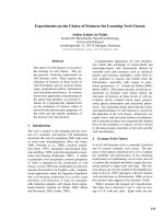
Draw your chassis design in standard pro-e as a solid “brick” – see Figure 1. Remember to
make sensible choices of datum plane positions – you will be pleased you did later. Select,
under “APPLICATIONS”, the sheet metal option and from the SMT CONVERT menu
that appears choose shell. It is now necessary to select which faces of the solid will be
removed, bearing in mind that one piece of material from the flat pattern cannot be in two
places at once. Once surface choices are complete you will be asked for the material
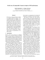
thickness. The sheet steel used for IDP construction is 0.7mm. Figure 2 shows the resulting
shell.
Figure 1
Figure 2
. 3
2.2 Sheet metal conversion
2.2.1 Ripping
The shell in Figure 2 does not yet represent a piece of bent sheet metal, as it is not
yet obvious which edges are folded and which are not continuous (“ripped”). Select the
“create conversion” feature (the top icon to right of model screen) and the SMT
CONVERSION dialogue box will appear (see Figure 3) with all five feature types shown as
“optional”.
Figure 3
Highlight Edge Rip and Define and select the edges that will be discontinuous.
Highlight Bends and Define and select all edges to be formed by bending.
Selecting Done Sets results in default radii being applied from part bend table.
The actual bend radius achieved on the hand bender in the workshop, with this material, is
1.7mm (internal). Highlight Bends and Define once more and choose Select All and Done,
whereupon a further dialogue box “REDEFINE BEND SETTINGS” appears (see Figure 4).
Highlight Radius and Define, select Enter Value and ensure that 1.7 is set as internal
radius.
Figure 4
2.2.2 Bend Definition
The bend properties of the IDP materials are shown in the following diagram. Note
that the Aluminium alloy is 1.5mm thick and that an internal bend radius of 1.6 is achieved.
. 4
2.2.3 Flat Pattern
It should now be possible to produce a development of the model by selecting
“Create Flat Pattern” icon from the lower right edge of model display screen. Check
that the model is now flat, by selecting any saved view other than Top or Bottom. Any
edges still folded indicate that not enough edge rips were selected. Check also that a
consistent bend allowance of 3.1 has been allocated (note that the easiest way of doing
this is by starting a drawing file of your chassis and showing all dimensions).
Figure 5
2.2.4 Relief
In Figure 5 a typical flat pattern is shown. Note that as no corner relief was selected
then sharp darts are cut into the start of the bend, resulting in a high rate of material
deformation in this corner. Although, for the thin material being used, this is acceptable, the
ease of bending will be improved by removing some material from this area.
. 5
Choose Redefine and the Smt Conversion from the family tree to redisplay the
dialogue box in Figure 3. Highlight Corner Reliefs and Define and see the effect of
choosing one of the options shown in Figure 6. Recommended dimensions are shown.
Figure 6
Another nicety is illustrated in Figure 7 where part of a sheet is to be bent down and
part not. Although Pro-E does offer bend relief for such instances, cutting machines cannot
produce slits of zero width. It is, therefore, suggested that a cut is inserted which goes just
beyond the bend area, terminating in a full radius, as shown.
Figure 7
Note that sometimes it is necessary to provide much more corner relief than the
above options, where, for example, overlapping tabs are required as shown in section 3.6.
. 6
2.3 Adding Cuts
To save time it is strongly recommended that all mounting holes and cut-outs are
included in the initial cutting stage to avoid the need for drilling later.The “Flat Pattern”
feature, like any other in the model tree, can be suppressed and resumed at will. This allows
you to toggle between the development and the folded up form of the model. Mounting
holes and other features are added to the folded form, and will automatically be placed
correctly on the flat pattern.As in the example below this is also true of cuts sketched on a
plane at 90 degrees to the plane of the flat pattern. Note that the flat pattern will always
arrange itself to be the final feature on the family tree. There are 3 methods of making holes
and cuts, the SMT Cut icon to the right of the screen , and from the INSERT menu either
Extrude or Hole (although hole will only do round ones).
2.4 Family Table
It is vital to define a Family Table for all folded components as they will be required
in both bent and flat forms in drawings, and in the folded form in assembly models. The
family table should be started as soon as possible so that the correct instance can be
inserted. From the TOOLS menu select Family Table and the following box appears -
. 7
Select the “Add a Column” icon and the dialogue box shown appears:
Highlight Feature under “Add Item”
and select the Flat Pattern so that the
form looks as the one depicted.
Accept selections with OK.
Returning to the Family Table window will show it to be partially filled in.
Selecting the “Add a row” icon allows a futher instance to be added.
Suggest it be called “chassis_folded”. Note that the generic will have the flat pattern
turned on and the folded instance must have it turned off so that the form will now appear
thus.
From now on, whenever this model is inserted into an assembly or a drawing you
will be asked which instance you require. Never put the generic model away with the Flat
Pattern feature suppressed as this causes trouble with references in assemblies and
drawings.
Do a Family Table before inserting the model into either an assembly
or a drawing!
. 8
3 Evolving the Design
Should the structure of the chassis need modifying, during the design process, then there
are several techniques to choose from.
3.1 Simple Modification of Dimensions
To modify the overall size of the chassis one can return to the original solid extrusion. To
increase, for example, the overall length of the chassis is straightforward. Suppress the Flat
Pattern feature, choose Modify from the PART MENU and select the original extrusion.
The relevant dimension can now be simply altered, although care must be taken that other
features such as holes are still in the desired position. See below.
However the same approach cannot be used if it is required to increase the depth of the
skirt. This cannot be achieved all round the chassis, as the tabs bent down in the central
portion must remain narrower than the slots from which they are cut. Therefore the original
extrusion cannot simply undergo a dimension modification but must be Redefined to
include a cut giving a step in depth around the problem area. This creates more surfaces and
so the First Wall feature must be redefined to produce the desired shell. This, in turn,
means that the Smt Conversion feature may need redefinition to re-establish the rips and
bends and to achieve this any corner reliefs must be temporarily removed as their
references will go missing in the process. This is, clearly, too complicated and so it is
recommended that Redefinition of the original feature is avoided and simpler techniques
applied.
. 9
3.2 Simple Wall Extension
To extend walls individually, in the simplest way, choose the Create Extended
Wall icon (6
th
from top at right of model window). A dialogue box appears prompting
firstly the selection of an edge to be extended and then a distance. Choose Use Value
option and then, ignoring suggested values, choose Enter, allowing a value to be typed in.
Figure A shows the rear wall extended by 6mm.
Figure A
Figure B
NB – Remember to take account of Parent / Child relationships.
To extend walls with cuts in their edges, as with the side walls, the extension should be
placed before the cut in the family tree to produce the required result, as shown in Figure B
above.
. 10
To carry out any more complicated modifications, from making an extension to only
part of the length of an existing wall to adding a complex profile with specified bend
angles or providing a folded “safety edge”, the 2
nd
and 3
rd
Icons down are used.
Create Flat Wall
Create Flange Wall
“Flat” wall simply means that the shape is defined by sketching on the flat face, it may
still be attached to the existing wall via a single bend of any angle.
“Flange” wall is effectively the same as “extruded” and means that the sketch is
edgewise on, therefore complex bend profiles may be defined although they must be
constant over the length of attachment. This command allows attachment to curved edges.
Both of these commands operate with a dashboard type display of parameters to be
defined, with the provisional wall shown in lime-green so that the effect of any alterations
can be seen graphically before being committed to.
Both have the facility for calling up standard shapes whose dimensions can be
edited on a simple graphic menu, or to be user-defined by entering the sketcher.
3.3 Non-uniform Extension of walls
To extend walls by an amount varying over the length of the edge in question,
choose the Create Flat Wall icon (2
nd
from top). The following dashboard appears.
Pick the edge to attach to and set the shape to
Rectangle as well as the angle to Flat :-
Under the SHAPE tab
a simplified sketch can
be displayed and edited
as shown below :-
. 11
Note that the effect of changes can be seen “live” in the lime green rendered wall in
the main window. The example shown is a simple rectangular addition over the length of
the attachment edge minus 16mm; observe that the first time the number 16 is entered a
minus sign must be used. Ready-made shapes available for this feature include
“Trapezoid”, “L” and “T” while any flat shape can be defined by selecting “User
Defined” and entering the sketcher.
3.4 Adding Walls with Bends
This command also allows walls to be attached via a bend, by selecting the required
angle in the field that had been set to Flat above.
In the example below, a box with 4 sides bent up has a further return added. As we
require to make this addition to all 4 sides, the shape will be trapezoidal, with 45° ends, to
avoid interference. Note the effect of the various flip arrows – modifications can be seen
“live” in the model window.
Accepting the options above gives the result shown:
. 12
3.5 Copying of Features
To repeat the feature on all 4 walls the “copy and paste” method can be used.
Highlight the feature to be copied and under the EDIT menu select Copy. The Paste and
Paste Special commands are now available.
Paste allows an independent copy to be
created on any selected edge. However, in this case
it would be preferrable to have dependent copies,
i.e. copies which change to match alterations made
to the original feature.
Therefore select Paste Special and in the
dialogue box which appears (see opposite) tick
the box for dependency as shown.
OK-ing this causes the dashboard to appear
and it simply remains to select the attachment edge
required for the copy. Ensure that if the external
edge was selected for the original then the same is
selected here and vice-versa.
Note that the “clipboard” is now empty and that further pasting operations require
the master feature to be highlighted and copied each time. Repeating the procedure for each
wall produces the structure shown:
If the dimensions of the original trapezoidal wall are now varied then the copies will
change as well. If, however, a difference was required then any dependent feature can
always be made retrospectively independent by highlighting it and using the Make Sec
Indep option from the RMB menu.
Note that, in this case, the new walls all extend over the entire length of their
attachment edges despite being of differing lengths. This is because they are defined as
doing this. If the original feature had been sketched and had been defined with all finite
dimensions rather than attached to ends of existing entities, then some modification of
copies might have been necessary to achieve the desired result.
. 13
3.6 Tabs Requiring Bend Relief
In our example, it is desired to stiffen the chassis by extending the side walls into
tabs to be bent round and pop-riveted to the end walls, as below.
The neatest result is obtained by folding the tabs behind the adjacent end wall. This
can be achieved with the same “Create Flat Wall” command which will ensure correct,
flush alignment of surfaces automatically.
Enter the dashboard for this command as before, highlight the attachment edge (it is
suggested that a consistent choice of outside edge is chosen) and define the shape. A nice
little wrinkle is to use a trapezoid with a very slight angle (eg. 2 degrees) to provide
clearance from the top edge and from the bend at the base, in case the bending is not quite
100% accurate.
Use the flip arrows to ensure that the tab goes the right way and that it lies flush
against the end wall, not coincident with it.
. 14
At the bottom corner of the tab, where its
bend meets the bend between base and
side wall, there is a region of infinite
deformation. This must be resolved by
some sort of relief and the default (set
under the dashboard heading RELIEF)
is a simple rip, giving the effect shown
highlighted opposite.
This is actually undesirable, as it
would be both difficult to bend and
would leave a dangerous sharp corner.
Instead some material would be removed from this area to avoid the situation altogether.
Although there are bend reliefs available from the dashboard defining the wall in question,
these do not work very well when adjacent to other bends (their purpose is to lie between
bent material and flat material, as shown later).
There are 2 recommended methods to resolve this:
Using original Corner Relief
Return to the SMT Conversion feature and edit its definition.
Select Corner Reliefs from the SMT Conversion
definition window and Define, select all corners and Done.
This makes the Redefine Bend Settings window
appear as shown below. Highlight Corner Relief and Define
and then select Circular. Choose Enter Value and set
diameter to 5mm (This is the value required to avoid all
traces of a rip relief).
Accept by OK'ing boxes and Done Sets. This results in the Flat Pattern now
showing large circular cut-outs at the corners. However, if the Flat Pattern is suppressed, it
will be observed that the corners look the same as before on the folded-up version (ie with
no relief). This is because the cuts cannot be computed until the fabrication is flat and, at
the moment, the Flat Pattern feature is the first time that the sheet has been flat.
To observe the effect in the folded-up model, it is necessary to insert two features
into the model tree.
First the Unbend feature, using the eighth icon down
Follow this with the Bend Back feature from the flyout from Unbend
. 15
For both of these features a surface or edge must be selected to stay fixed,(make it
the same reference for both features) and the options: Unbend All and Bend Back All
should be chosen. Now, if the Flat Pattern is suppressed, the folded corner looks like this:-
Note that the regions of bent metal are separated by the circular relief.
Using relief added by hand in the unbent state
The method above does result in quite a large hole in the corner but it is possible to
remove the minimum amount of material if done manually. Add an Unbend feature as
above and examine the flattened corner detail as example below.
A sheet metal cut can be inserted into the flattened material to remove the line
shown, where two bent regions meet.
. 16
The first sketch shown below removes a triangle, whereas the second removes a
circle attached to points at the junctions of the bend zones (diameter comes out at about
3.4). Note that in both cases there are no dimensions because existing features are used for
all definitions. (Hint: In the sketcher, add 3 points first.)
Their effects in the folded state are shown below.
The cut feature can be mirrored onto the opposite corner by selecting it (either from the
model or the tree) and choosing Mirror from either the EDIT pull-down menu or the icon
at the bottom right corner of the screen.
A mini dashboard appears, on which the only item which must be filled in is the mirror
plane selection. Note that under Options one can choose whether the copy is
independent or dependent upon the original (ie will update automatically when the
original is modified).
To mirror onto the back corners a datum plane could be inserted halfway down the
chassis. Alternatively either 2 or all 4 corners could be cut on the same sketch.
. 17
3.7 Adding Bent Tabs from a Flat Background
The same “Create Flat Wall”command allows tabs to be bent up from surrounding flat
material in the manner shown below. In the example being used it is first necessary to cut
away the side walls where the tabs are required. It is also desirable to be able to alter the
positions of these features by editing one single dimension and so an auxiliary datum plane
may be inserted at an offset from the front plane.
Use Sheet Metal Cut to remove a rectangle of material symetrical to auxiliary datum
(DTM2) and attached to outer surface of side wall. Only two dimensions will be shown on
the sketch, width and depth as seen below.
This cut may be mirrored about the MID datum plane, using “options” on the
dashboard to make the copy dependant, (thus ensuring ease of subsequent modification
while maintaining symmetry of chassis).
. 18
Select Create Flat Wall icon and pick edge of cut for attachment as shown. Define
shape, angle and bend radius.
This case is where the inbuilt relief options are particularly useful. Open the RELIEF
menu from the dashboard.
It is recommended that the options shown
opposite are used -
Leave both sides the same
Choose Obround.
Select “Tan to Bend” as the length.
Select “Thickness x 2” as the width.
Note that the material removed is from the
surrounding flat area – the tab width is
unaffected.
These choices result in a flat
pattern that is both easy to cut and to bend
and which produces the result pictured
opposite.
. 19
This feature can now be copied to the other cut using the “Copy & Paste” method
previously described. Remember to use “Paste Special” to make the copy dependant. Note
that using the mirror function on this feature does not produce the simple result expected
and is unnecessary if the tab is, itself, symmetrical.
Cuts can be added to these walls, noting that if MID datum plane is selected as the
sketching plane then “Through All” produces the result below. Reference the cuts to
DTM2 horizontally and surface of chassis vertically.
Should the model need modifying then the position of the whole feature can be
controlled with the dimension to DTM2 and the width of spacing by the depth of original
cuts. The width of brackets is controlled by the width of original cuts and the height of
brackets by the bracket definition. The cuts and the holes should always remain
symmetrical to DTM2 as this is how they were originally defined
It is always a good idea to spend a little time considering how to define positions and
refer dimensions in order to simplify subsequent modification.
. 20
3.8 Create Flange Wall
All the above modifications and additions have used the Create Flat Wall function.
However, occaisionally, it is useful to be able to create an extra wall by sketching on its
edge and then extruding the profile, as, for example, when multiple bends are required.
To create an integral sensor bracket, for example, the dashboard shown below is
entered by selecting the third icon down
Select the desired attachment edge for Placement, under Profile go to the User
Defined option and enter the sketcher (sketching on the MID datum plane), specify the
length as symmetrical about the sketch plane and use some relief (obround is
recommended). Note that the bend radius at the attached edge is automatically specified on
the dashboard but the integral bend can either be sketched at the required radius, or left
sharp on the sketch so that the “add bends to sharp edges” tick-box can be used to link this
bend to the radius on the dashboard as well. When in the sketcher it is not necessary to
thicken the sketch as the direction of thickening is controlled by a flip-arrow on the
dashboard.
Other possibilities offered by this command include the ability to attach to a curved
edge but to manufacture this type of feature would require more sophisticated forming
equipment than is available. Also, under the standard profiles are included various types of
“safety edge” where material is folded to avoid sharp edges, but these are not considered
relevant to the IDP.
. 21
4 Output
Dimensioned drawings must be produced to gain Design Approval. They should be
included in the relevant reports and are also your record of the design and are useful as
discussion documents whilst modifications are considered.
4.1 Drawings
Start a new drawing and select “Empty with Format”, browsing for a suitable
CUED border. When in the drawing, add both “generic” and “folded” instances of the
model – from RMB menu choose Properties and then Drawing Models. Select Add
Model from the DRAWING MODELS menu and insert chassis model twice, once in each
instance. Use Set Model from the DRAWING MODELS menu to determine which
instance views are added from.
As most features have been defined in the folded state, it is best to dimension these
in the folded views. This includes holes, cuts and overall sizes as in the example below.
Note that it is permissable to use a note about symmetry to minimize the number of
dimensions, provided the intention is unambiguous. Note that it is not possible to rely upon
the automatic dimensioning provided by Pro-E, there will always be extraneous dimensions
generated and it will always be necessary to insert some dimensions manually.
It is still necessary to produce flat views(from the generic instance of the model) but
the only features which must be dimensioned on these are the bend lines (which must be
scribed by hand in the workshop later).
. 22
It is acceptable to dimension to one side or the other of bends or even to their centre
line, provided that dimensions appear stating the relationship between these. Such
dimensions may be shown once as “TYPICAL” as in the example above.
4.2 DXF
The cutting machine requires a DXF file to be produced. Start a new drawing file,
choosing Empty, Landscape and A2 size. Attach the generic instance of the model and
Add a Top View at a scale of 1:1. Ensure that no notes or dimensions are displayed and
also remove bend lines by choosing Disp Mode from VIEWS menu and selecting View
Disp. Select the only view and highlight No Disp Tan, then Done/Return. The view will
now be left with only cut lines displayed.Choose command “Save a Copy” of the file and in
the dialogue box change File Type to DXF. It is helpful to produce one DXF file for all
components in 0.7mm steel and one (if applicable) for all components in 1.5mm
aluminium. Do this by attaching all relevant models to the drawing and selecting new
model for each view. Take care that all scales are 1:1.
Drawing file appearance prior to creation of DXF file.
. 23
Determine the order in which bends are to be executed – if in doubt seek advice
from workshop technicians. The cut sheet should have bend lines scribed upon it to show
the start of each bend. Be careful to scribe upon the side of material that will be uppermost
(and therefore visible) in the bending machine.
5 Assembly Modelling
5.1 Parts Library
It is strongly recommended that the entire assembly is modelled before gaining
design approval and starting manufacture. To help with this, models of the standard
component parts have been placed in the MDP library. This is accessed, from the “Open
File” dialogue box, by changing directory to CUED Library and then selecting mdp_lib.
The library structure is shown below and it will be found that each section has a description
of the contents.
Use the Preview facility offered by Pro-E to see the file before opening it. Note that
some of the items have been pre-assembled to save time. Also note that the gears are shown
as smooth drums of the pitch-circle-diameter. To mesh the gears ensure that these circles
are just touching. However to check the overall space envelope required by a gear,
Suppress the final cut and a new outer surface (coloured yellow) will be revealed.
When building up a large assembly, it is much easier to use sub-assemblies, rather
than bringing loads of individual components into the top-level model. For instance:
. 24
assemble the motor, shaft extension and wheel (already done in the library), together with a
suitable bracket of your own devising, into a drive-unit assembly before inserting this into
the overall robot, thus saving having to do everything twice and minimising the number of
datum features that need to be displayed when positioning things.
5.2 Standard Brackets and other materials
In addition to the chassis, there will, probably, be a requirement for auxiliary
brackets formed from sheet metal. To save time, a small library of standard brackets has
been compiled, which can be modified to individual requirements. Note that from wherever
library files are obtained, they are kept as read-only. It will be necessary to save a re-named
copy to allow modification. The types of brackets offered are shown below.
There are also short lengths of the bar and angle materials which may be used
similarly.
5.3 Assembly Tips
When placing parts in an assembly model, remember that when one or two
constraints have been made then the part may be moved by hand (in the remaining degrees
of freedom only) by holding Ctrl & Alt while using the MMB for rotation and the RMB for
translation. There is nothing wrong with leaving a component partially constrained while
other parts and features are arranged.
If it is required to add a mounting hole to match a placed component, this can be
done from within the assembly model by using the “Activate” facility. A typical procedure
might be -
Insert a component into the assembly and place known constraints upon it. (eg:
mounting surface to surface of chassis, orientation of faces and edges).
Position the component by hand to roughly the right position in remaining plane(s).
Activate the chassis model (highlight and RMB menu). Observe little green diamond.
Cut a hole to match that in placed component, possibly using concentric circles.
Place dimensions on cuts using references in chassis model alone. Resolve redundant
dimensions and constraints as prompted (by deleting coincidences).
Tweak dimensions to round numbers as required.
Accept cut feature if satisfactory.
Re-Activate assembly model (highlight top level of model tree and use RMB menu).
Return to definition of placement of partially constrained component and add constraint
aligning mounting holes.
. 25